1
PowerPanel® Business Edition
User’s Manual
Rev. 15
2014/04/14
™
PowerPanel Business Edition
ELECTRONIC END USER LICENSE AGREEMENT FOR CYBERPOWER POWERPANEL BUSINESS
EDITION
NOTICE TO USER:
THIS IS A CONTRACT. BY INSTALLING THIS SOFTWARE YOU ACCEPT ALL THE TERMS AND
CONDITIONS OF THIS AGREEMENT. The End User License Agreement and copyright of CyberPower
®
PowerPanel Business Edition product and related explanatory materials ("Software") are owned by its
Cyber Power Systems (USA), Inc. The term "Software" also shall include any upgrades, modified versions or
updates of the Software licensed to you by Cyber Power Systems (USA), Inc. Please read this Agreement
carefully. At the end, you will be asked to accept this agreement and continue to install or, if you do not wish
to accept this Agreement, to decline this agreement, in which case you will not be able to use the Software.
Upon your acceptance of this Agreement, The Cyber Power Systems (USA), Inc grants to you a
nonexclusive license to use the Software, provided that you agree to the following:
1. Use of the Software. You may install the Software on a hard disk or other storage device; install and use
the Software on a file server for use on a network for the purposes of (i) permanent installation onto hard
disks or other storage devices or (ii) use of the Software over such network; and make backup copies of the
Software.
You may make and distribute unlimited copies of the Software, including copies for commercial distribution,
®
as long as each copy that you make and distribute contains this Agreement, the CyberPower PowerPanel
Business Edition installer, and the same copyright and other proprietary notices pertaining to this Software
that appear in the Software. If you download the Software from the Internet or similar on-line source, you
must include the copyright notice for the Software with any on-line distribution and on any media you
distribute that includes the Software.
2. Copyright and Trademark Rights. The Software is owned by the Cyber Power Systems (USA), Inc and its
suppliers, and its structure, organization and code are the valuable trade secrets of its Cyber Power Systems
(USA), Inc and its suppliers. The Software also is protected by United States Copyright Law and International
Treaty provisions. You may use trademarks only insofar as required to comply with Section 1 of this
Agreement and to identify printed output produced by the Software, in accordance with accepted trademark
practice, including identification of trademark owner's name. Such use of any trademark does not give you
any rights of ownership in that trademark. Except as stated above, this Agreement does not grant you any
intellectual property rights in the Software.
3. Restrictions. You agree not to modify, adapt, translate, reverse engineer, decompile, disassemble or
otherwise attempt to discover the source code of the Software. Although you may customize the installer for
®
the Software as documented on the CyberPower PowerPanel Business Edition Disk (e.g., installation of
additional plug-in and help files), you may not otherwise alter or modify the installer program or create a new
installer for the Software.
2
™
PowerPanel Business Edition
4. No Warranty. The Software is being delivered to you AS IS and its supplier makes no warranty as to its
use or performance. THE CYBER POWER SYSTEMS (USA), INC. AND ITS SUPPLIERS DO NOT AND
CANNOT WARRANT THE PERFORMANCE OR RESULTS YOU MAY OBTAIN BY USING THE
SOFTWARE OR DOCUMENTATION. THE CYBER POWER SYSTEMS (USA), INC. AND ITS SUPPLIERS
MAKE NO WARRANTIES, EXPRESS OR IMPLIED, AS TO NONINFRINGEMENT OF THIRD PARTY
RIGHTS, MERCHANTABILITY, OR FITNESS FOR ANY PARTICULAR PURPOSE. IN NO EVENT WILL
THE CYBER POWER SYSTEM, INC. OR ITS SUPPLIERS BE LIABLE TO YOU FOR ANY
CONSEQUENTIAL, INCIDENTAL OR SPECIAL DAMAGES, INCLUDING ANY LOST PROFITS OR LOST
SAVINGS, EVEN IF THE CYBER POWER SYSTEMS (USA), INC. REPRESENTATIVE HAS BEEN
ADVISED OF THE POSSIBILITY OF SUCH DAMAGES, OR FOR ANY CLAIM BY ANY THIRD PARTY.
Some states or jurisdictions do not allow the exclusion or limitation of incidental, consequential or special
damages, or the exclusion of implied warranties or limitations on how long an implied warranty may last, so
the above limitations may not apply to you.
5. Governing Law and General Provisions. This Agreement will be governed by the laws of the State of
Minnesota, U.S.A., excluding the application of its conflicts of law rules. This Agreement will not be governed
by the United Nations Convention on Contracts for the International Sale of Goods, the application of which
is expressly excluded. If any part of this Agreement is found void and unenforceable, it will not affect the
validity of the balance of the Agreement, which shall remain valid and enforceable according to its terms.
You agree that the Software will not be shipped, transferred or exported into any country or used in any
manner prohibited by the United States Export Administration Act or any other export laws, restrictions or
regulations. This Agreement shall automatically terminate upon failure by you to comply with its terms. This
Agreement may only be modified in writing signed by an authorized officer of Cyber Power Systems (USA),
Inc.
3
™
PowerPanel Business Edition
Table of Contents
Introduction ...................................................................................................................................................... 6
Agent ............................................................................................................................................................. 7
Client.............................................................................................................................................................. 7
Center ............................................................................................................................................................ 7
Getting Started ................................................................................................................................................. 8
Prerequisites .................................................................................................................................................. 8
Hardware Limitation .................................................................................................................................. 8
Operating System ...................................................................................................................................... 8
Web Browser ............................................................................................................................................. 8
Installation ..................................................................................................................................................... 8
Installation on Windows ............................................................................................................................. 8
Installation on Linux ................................................................................................................................. 11
Installation on VMware ESXi and ESX .................................................................................................... 15
Virtual Appliance Deployment on ESXi ................................................................................................... 16
Installation on XenServer ........................................................................................................................ 20
Installation on Hyper-V Server ................................................................................................................ 20
®
Accessing PowerPanel Business Edition .................................................................................................. 20
Login ........................................................................................................................................................ 21
Essential Setup ............................................................................................................................................ 22
Agent ....................................................................................................................................................... 22
Client ....................................................................................................................................................... 22
Center ...................................................................................................................................................... 23
Using PowerPanel Business Edition Agent and Client ............................................................................. 23
System ......................................................................................................................................................... 23
Summary ................................................................................................................................................. 23
Information............................................................................................................................................... 24
UPS ............................................................................................................................................................. 24
Status ...................................................................................................................................................... 24
Information............................................................................................................................................... 29
Configuration ........................................................................................................................................... 30
Diagnostics .............................................................................................................................................. 35
Load ......................................................................................................................................................... 37
Power........................................................................................................................................................... 40
Information............................................................................................................................................... 41
Configuration ........................................................................................................................................... 42
Event Action ................................................................................................................................................ 45
4
™
PowerPanel Business Edition
Events ...................................................................................................................................................... 45
Notification Recipient ............................................................................................................................... 53
Action Settings......................................................................................................................................... 55
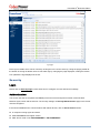
Logs ............................................................................................................................................................. 61
Event Logs ............................................................................................................................................... 61
Status Records ........................................................................................................................................ 62
Settings .................................................................................................................................................... 64
Schedule ...................................................................................................................................................... 64
Shutdown................................................................................................................................................. 65
Security ........................................................................................................................................................ 66
Login ........................................................................................................................................................ 66
Authentication .......................................................................................................................................... 68
Network ................................................................................................................................................... 71
Preferences ................................................................................................................................................. 75
User Experience ...................................................................................................................................... 75
Help ............................................................................................................................................................. 76
Content .................................................................................................................................................... 76
About ....................................................................................................................................................... 76
Logout .......................................................................................................................................................... 76
Using PowerPanel Business Edition Center .............................................................................................. 77
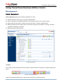
Management ................................................................................................................................................ 77
Power Equipment .................................................................................................................................... 77
IT Equipment ........................................................................................................................................... 92
Logs ............................................................................................................................................................. 99
System Logs ............................................................................................................................................ 99
Security ...................................................................................................................................................... 100
Login ...................................................................................................................................................... 100
Authentication ........................................................................................................................................ 100
Network ................................................................................................................................................. 102
Help ........................................................................................................................................................... 102
Content .................................................................................................................................................. 102
About ..................................................................................................................................................... 102
Logout ........................................................................................................................................................ 102
Technical Support ....................................................................................................................................... 102
Troubleshooting ......................................................................................................................................... 102
FAQ ........................................................................................................................................................... 107
Glossary ....................................................................................................................................................... 115
5
™
PowerPanel Business Edition
Introduction
®
PowerPanel Business Edition (PPBE) software provides comprehensive advanced power management
for UPS/PDU/ATS systems. It controls unattended shutdowns, scheduled shutdowns, and notifications for
computers powered by the UPS (Uninterruptible Power Supply) PDU (Power Distribution Unit) or the ATS
(Automatic Transfer Switch).
®
PowerPanel Business Edition software consists of Agent, Client and Center. The Agent monitors and
configures the UPS through the USB or serial connection. It logs the UPS status and power events, and
generates action in response to events. The Client establishes communication with the Agent, UPS
RMCARD and PDU, and generates actions according to notifications from the UPS/PDU/ATS when a power
event occurs. The Center simultaneously monitors and controls multiple UPS/PDU/ATSs and computers
which have Agent or Client installed via the local network. It also logs events and results about commands
for power management.
The Agent should be installed on a single computer connected to the UPS with a USB or serial connection.
The Agent controls the UPS and establishes communication with the Client if the UPS has no remote
management card. The Agent relays the UPS state to each Client and the Client performs actions based on
the notifications. Each computer powered by the UPS can be protected and controlled using the Client. In
the event of power failure, the Agent will shut down the hosted computer and request the Client computers to
®
shut down prior to the UPS shutting down. Refer to Configuration A of the PowerPanel Business Edition
structure illustration.
®
PowerPanel Business Edition structure
A UPS with a remote management card has the ability to communicate with multiple computers which
have Client installed and are on the same network and relay the UPS status to each Client. In the event of a
power failure, each Client will request the hosted computer to shut down following notifications from the UPS.
®
Refer to Configuration B of the PowerPanel Business Edition structure illustration.
6
™
PowerPanel Business Edition
The Client also has the ability to communicate with a PDU. Each computer powered by a PDU can utilize the
Client for protection and control. When a PDU outlet supplying power to a computer running Client is going to
be switched off, the Client will perform a shutdown prior to switching off the power. Refer to Configuration C
®
of the PowerPanel Business Edition structure illustration.
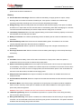
Agent
Aside from the primary function of shutting systems down in the event of an outage, the Agent also provides
the following functions:
Unattended shutdown in response to various power conditions.
User notification of power conditions.
Flexible configuration of actions for each event and notifications via E-mail, Instant Message, and SMS.
Run command files for custom applications.
Historical logs of events and power conditions.
Detailed load management for all powered equipment.
Scheduled shutdown and restart.
Status monitoring of the UPS and utility power.
UPS configuration.
Quick view system summary.
Client
The Client provides unattended shutdown for the hosted computer following a notification from the
UPS/PDU/ATS. The Client also provides the following functions:
Unattended shutdown in response to various power conditions.
User notification of power conditions.
Flexible configuration of actions for each specific event and notifications via E-mail, Instant Message,
and SMS.
Historical logs of power events.
Quick view system summary.
Center
The Center provides users the following functions for multiple:
Simultaneous monitoring of multiple UPS/PDU/ATSs, equipment and computers which have Agent or
Client installed.
Control access to all monitored UPS, PDU, computers and equipment.
Detailed load management between UPS/PDU/ATS and all powered computers/equipment.
Equipment groups for easy monitoring or individual access.
Viewing additional information and status of monitored UPS, PDU, computers and equipment.
7
™
PowerPanel Business Edition
Historical logs for events and results about demands to power management.
Getting Started
Prerequisites
Hardware Limitation
733 MHz or higher Pentium-compatible CPU.
256 megabytes (MB) of RAM recommended minimum; more memory generally improves
responsiveness.
Minimum of 150 MB of free space of hard disk.
Serial port or USB port. (Required by the Agent)
Network interface.
Operating System
®
PowerPanel Business Edition software can be installed on the following operation systems:
32-Bit Versions:
Windows 8
Citrix XenServer 5 or later
Windows 7
Red Hat Enterprise 5.1
Windows Vista
Fedora 7 or later
Windows Server 2003
SUSE 10.1 or later
Windows Server 2003 R2
Debian 5.1 or later
Windows XP
Ubuntu 9.10 or later
Windows 2000
64-Bit Versions:
Windows Server 2012
Windows Vista
Windows Server 2012 R2
Windows Server 2003
Windows Hyper-V Server 2012
Windows Server 2003 R2
Windows Hyper-V Server 2012 R2
Windows XP
Windows 8
Ubuntu 11.04
Windows 7
Open SUSE 11.4
Windows Server 2008
VMware ESX/ESXi 4 or later
Windows Server 2008 R2
Note: Because of the abundance of different Linux builds, not all builds are tested with PowerPanel
®
Business Edition but most builds will be able to run the program.
Web Browser
®
PowerPanel Business Edition software is accessed using a web browser and is compatible with the
following browsers:
8
™
PowerPanel Business Edition
Microsoft Internet Explorer 7 or above
Firefox 2.0 or above
Google Chrome
Konqueror
Installation
Installation on Windows
®
A pop-up window will be displayed automatically when inserting the PowerPanel Business Edition
installation CD. Users can click the Install PowerPanel Business Edition shortcut on the pop-up window to
initiate the installation procedure. If the pop-up window is not displayed when inserting the CD, browse to the
CD drive and open the folder which locates at /Software/Windows, and then double click the file named
Setup.exe to start the installation procedure.
®
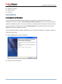
Use the PowerPanel Business Edition installation CD to complete the installation on the target computer. To
install follow these steps:
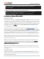
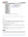
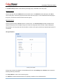
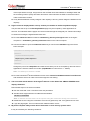
Click the Next button to start an installation.
Accept the license agreement.
8
™
PowerPanel Business Edition
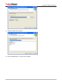
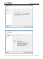
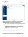
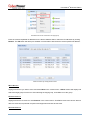
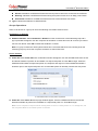
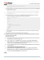
Choose the component. If one single computer is connected to the UPS directly via a USB or serial
connection, Agent should be installed. If the computer is powered by a UPS already connected to an
Agent, has a remote management card installed or is connected to a PDU, Client should be installed. If
the administrator requires simultaneous monitoring and access to multiple UPS/PDU/ATSs, equipment
and computers on a local network, Center should be installed.
Note: Agent, Client and Center cannot be installed on the same computer.
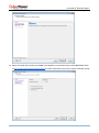
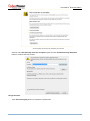
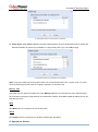
Choose the destination directory.
9
™
PowerPanel Business Edition
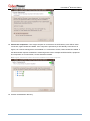
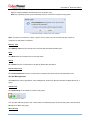
Choose the start menu directory.
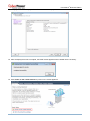
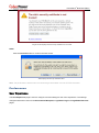
Click the Finish button to complete the installation.
10
™
PowerPanel Business Edition
Installation on Linux
The installer is used to install the software and requires root permission. The installation wizard will guide
users in completing the installation. Browse to the CD drive and find the installer in the /Software/Linux
folder. Initiate the wizard by running the ./ppbe-linux-x86.sh command or double clicking ppbe-linuxx86.sh on 32-bit systems or by running the ./ppbe-linux-x86_64.sh command or double clicking ppbelinux-x86_64.sh on 64-bit systems.
Note: On Linux systems, users may mount the CD by using the mount command. Run mount –t iso9660
/dev/cdrom /mnt/cdrom as a root user. /dev/cdrom is the CD drive and /mnt/cdrom will be the mount point.
To install follow these steps:
Click the Next button to start an installation.
Accept the license agreement.
11
™
PowerPanel Business Edition
Choose the component. If one single computer is connected to the UPS directly via a USB or serial
connection, Agent should be installed. If the computer is powered by a UPS already connected to an
Agent, has a remote management card installed or is connected to a PDU, Client should be installed. If
the administrator requires simultaneous monitoring and access to multiple UPS/PDU/ATSs, equipment
and computers on a local network, Center should be installed.
Note: Agent, Client and Center cannot be installed on the same computer.
Choose the destination directory.
12
™
PowerPanel Business Edition
The daemon ppbed will start during installation.
Click the Finish button to complete the installation.
13
™
PowerPanel Business Edition
Installation on Text Mode
When the system does not support graphic mode, the Linux installation needs to be initiated in the terminal
by using the ./ppbe-linux-x86.sh -c command on 32-bit systems or use ./ppbe-linux-x86_64.sh -c
command on 64-bit systems.
The installation procedure will be initiated as following steps:
Press Enter to start an installation.
Accept the license agreement.
Choose the component. If one single computer is connected to the UPS directly via a USB or serial
connection, Agent should be installed. If the computer is powered by a UPS already connected to an
Agent, has a remote management card installed or is connected to a PDU, Client should be installed. If
the administrator requires simultaneous monitoring and access to multiple UPS/PDU/ATSs, equipment
and computers on a local network, Center should be installed.
Note: Agent, Client and Center cannot be installed on the same computer.
14
™
PowerPanel Business Edition
Choose the destination location.
Installation procedure starts to process until the installation is complete.
Installation on VMware ESXi and ESX
Installation on ESXi
Installation must be launched in the vMA (vSphere Management Assistant) which is also a virtual machine
on the ESXi host; Agent should be installed on the vMA of ESXi 4.1 or later versions. In order to deploy vMA
on the ESXi host and install PPBE in the vMA, users must install the vSphere Client tool on another remote
computer first. To download the vSphere Client installer, users can enter the ESXi host IP address to access
the web page. Users can visit VMware website for vSphere Management Assistant Guide document
about vMA deployment on VMware ESXi.
The installer will guide users in completing the installation. Refer to Installation on Text Mode section to
follow the same steps to complete installation. The installer requires root permission to initiate the installation
procedure. Mount CD by running mount –t iso9660 /dev/cdrom /mnt/cdrom as a root user.(/dev/cdrom is
the CD drive and /mnt/cdrom will be the mount point.). Browse the CD drive and find the installer in the
/Software/Linux folder. Initiate an installation procedure by running the ./ppbe-linux-x86_64.sh command.
Before installing Agent with the USB or serial connection, make sure that the platform running the Agent
supports USB or serial connection. VMware ESXi 4.1 and later versions support a USB device to be passed
through from an ESXi host to vMA.
Note: In order to make sure that Agent on vMA of the ESXi host can establish communication with UPS
through USB connection, you should upgrade virtual hardware to the latest version. Refer to How do I
upgrade virtual hardware version of vMA of FAQ chapter from PowerPanel Business Edition User
Manual to know how to upgrade.
Note: In order to allow the interactions between physical and virtual machines, VMware tools have to be
installed on each virtual machine. Refer to VMware ESX/ESXi Server documentation for further information
about VMware Tools.
Installation on ESX
Installation must be launched in the Service Console (aka Console Operation System). To initiate the
installation procedure on VMware ESX also requires root permission. Use the same command to mount CD
and initiate the installation procedure.
15
™
PowerPanel Business Edition
Before installing Agent with the USB connection, make sure the host supports USB connection. ESX 4.1
does support USB devices. Refer to Installation on Text Mode section to complete the installation.
Virtual Appliance Deployment on ESXi
A virtual appliance (VA) is a prebuilt software solution, comprised of one or more virtual machines that is
packaged, maintained, updated and managed as a unit. It is fundamentally changing how software is
developed, distributed, deployed and managed.
Download the PPBE virtual appliance which is pre-installed Agent and Client from CyberPower. In order to
deploy the PPBE virtual appliance on VMware ESXi host, users must install vSphere Client tool on another
remote computer first. To download vSphere Client tool, users can enter the ESXi host IP address to
access web page of ESXi host.
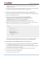
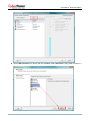
The deployment procedure will be initiated as below steps:
Launch the vShpere Client. Open the Deploy OVF Template window from File > Deploy OVF
Template… item.
Click Browse to import the ppbeXXX_centos.ovf extracted from the downloaded zip file. Click Next to
start a deployment task.
16
™
PowerPanel Business Edition
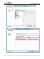
The OVF template detail is displayed. Click Next to continue.
17
™
PowerPanel Business Edition
Enter the name for the deployed virtual appliance. This name should be unique within the inventory.
Select the virtual disk format for the PPBE virtual appliance. The default option is Thin Provision. Refer
to About Virtual Disk Provision Disk Policies for further information about how to select virtual disk format.
18
™
PowerPanel Business Edition
A deployment detail is displayed. Click Finish to start the deployment task.
After the deployment task is complete, the PPBE virtual appliance will be added into the inventory.
Click Power on the virtual machine to power on the virtual appliance.
19
™
PowerPanel Business Edition
Login the virtual appliance. The default username and password are admin. In order to perform
shutdown accurately, you must change the time zone settings of the virtual appliance.
This can be a direct copy of the time zone file from the /usr/share/zoneinfo folder. We assume that the
host is located under the Chicago CST zone in Chicago, and the time zone can be changed by running
the command cp /usr/share/zoneinfo/America/Chicago /etc/localtime.
Installation on XenServer
®
The installer requires root permission to install the PowerPanel Business Edition. Mount CD by running
mount –t iso9660 /dev/cdrom /mnt/cdrom as a root user (/dev/cdrom is the CD drive and /mnt/cdrom will
be the mount point.). Browse the CD drive and run ./ppbe-linux-x86.sh command to initiate an installation
procedure.
Installation must be launched on the Dom0. Refer to Installation on Text Mode section to complete the
installation. Agent should be installed on the Dom 0 of XenServer 5 or later versions. Citrix XenServer 5.0
and later versions support USB device. Before installing Agent with the USB or serial connection, make sure
that the platform running the Agent supports USB or serial connection.
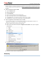
Installation on Hyper-V Server
®
Use the PowerPanel Business Edition installation CD to complete the installation on the target computer.
Run the <CD_Drive>\Software\Windows\setup.exe of the command prompt such as below illustration to
start the installation procedure (CD_Drive is a CD drive formatted as D: or E:). A popup window will be
displayed when the installation is launched. Refer to Installation on Windows section to follow the same
steps to complete installation.
Accessing PowerPanel ® Business Edition
20
™
PowerPanel Business Edition
®
The PowerPanel Business Edition web interface can be accessed following the directions below. To access
the web interface on a local computer, select Start > All Programs > CyberPower PowerPanel Business
Edition > PowerPanel Business Edition Agent, PowerPanel Business Edition Client or PowerPanel
Business Edition Center in the Windows Desktop or enter the http://localhost:3052 as the URL in the
browser.
Launching PowerPanel® Business Edition software on a local computer
On Linux, users can enter http://localhost:3052/ in the address of the web browser to access the interface.
Users can also enter the URL, http://localhost:3052/ in the local computer or
http://hosted_computer_ip_address:3052/ in the remote computer, to the address field of the web browser
®
to access the PowerPanel Business Edition software web interface. hosted_computer_ip_address is the
®
IP address of the computer which has the PowerPanel Business Edition software installed. For vMA on the
ESX or ESXi, hosted_computer_ip_address is the IP address of the vMA (Note:
hosted_computer_ip_address is the IP address of the host computer on ESX).
®
PowerPanel Business Edition supports multiple-language function and allows users to change language. It
will choose the suitable language as the default one to display at the initial access. Users can change the
language from the banner. After the language is changed, the page will refresh automatically and choose the
assigned language as the default one to display.
Change language
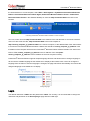
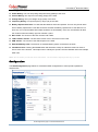
Login
The default username is admin and the password is admin. For security, it is recommended to change the
username and password on the Security/Login page after the initial login.
21
™
PowerPanel Business Edition
The local and remote login pages are the same.
Selecting the Remember me on this computer option on the login page allows the credentials to be
remembered for automatic logon at the next session. To terminate the session, click the Logout button on
the Logout page. The session will timeout and you will be logged out if no activity takes place during the
time of Session Timeout. The Session Timeout can be configured on the Security/Login page.
Essential Setup
®
In order to ensure the PowerPanel Business Edition software functions properly, make sure that the Agent,
Client and Center have been configured correctly.
Agent
Make sure a USB or serial cable is connected between the Agent computer and the UPS. If Agent is
installed on a vMA running on an ESX/ESXi host, refer to FAQ chapter for further details how to add
USB connection. If Agent is installed on a vMA running on ESX/ESXi 5.x, refer to FAQ chapter to
upgrade virtual hardware in order to add the USB device of target UPS.
NCL (Non-Critical Load) outlets on specific models are designed to shut off under certain
circumstances to save battery power and maximize the runtime on the remaining outlets. The Agent
computer should not be connected to NCL outlets. Refer to PPBE Installation Guide for UPS without
RMCARD for detailed information about how to plug the Agent computer into the correct outlets.
Configure the Necessary shutdown time option properly on the Event Action/Settings page based off of
how long it takes for that computer to turn off completely after a shutdown has been initiated.
Perform a battery test to verify the UPS can supply battery power to the connected equipment and the
equipment operates properly. See the UPS/Diagnostics section for more details.
Client
22
™
PowerPanel Business Edition
Setup the SNMP community the same as in the remote management card of the UPS/PDU/ATS, or the
Secret Phrase used by the Agent on the Security/Authentication page.
Set the port used by Client on the Security/Network page to match the port used by the Agent’s port.
Assign the network address of the remote management card of the UPS, PDU or Agent, and assigning
the connected outlet on the Power/Configuration page.
Configure the Necessary shutdown time option on the Event Action/Settings page based off of how
long it takes for that computer to turn off completely after a shutdown has been initiated.
Center
In order to establish communication with the UPS, PDU, Agent or Client. Set the SNMP Community to
the same one used in the UPS/PDU/ATS, or the Secret Phrase used by the remote card of UPS, PDU,
Agent or Client on the Security/Authentication page.
Setup that the port used by the Center on the Security/Network page to match the port used by the
Agent or Client.
Using PowerPanel Business Edition Agent and Client
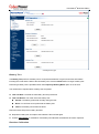
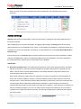
System
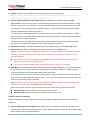
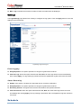
Summary
System/Summary page in Agent
23
™
PowerPanel Business Edition
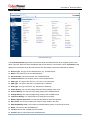
In Agent, the Summary page provides an overview of the system operation. This includes the utility power
status, operating status of the UPS, issues with the system and items requiring user attention.
In Client, the Summary page provides an overview of the system, including the communication status with
the UPS/PDU/ATS, issues with the system and items requiring user attention.
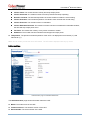
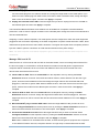
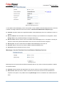
Information
(The content in this section is only applicable to the Client.)
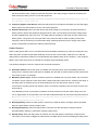
System/Information page
The Information page shows detailed information about the Client as follows.
Name: The name of the hosted computer, e.g. Web Server or Bill's Computer.
Location: Where the hosted computer is located, e.g. Server room or Rack A.
Contact: Who to contact about this hosted computer, e.g. someone's name, E-mail or phone number.
UPS
(The content in this section is only applicable to the Agent.)
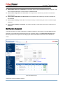
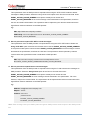
Status
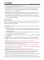
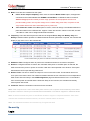
The UPS/status page displays detailed status on the UPS power conditions, batteries, and system.
24
™
PowerPanel Business Edition
UPS/Status page of a PR1000LCDRTXL2Ua
Input
Status: Displays the present status of the utility power supplied to the UPS.
Normal: The voltage and frequency of the utility power is normal.
Blackout: There is no utility power being supplied to the UPS and it is supplying battery power to
connected equipment.
Over Voltage: The utility voltage is higher than the high voltage threshold and the UPS is using the
battery to supply power.
Under Voltage: The utility voltage is lower than the low voltage threshold and the UPS is using the
battery to supply power.
Frequency Failure: The frequency of the utility power is out of tolerance and the UPS is supplying
battery power with a fixed frequency.
Wiring Fault: The UPS has detected a wiring fault in the outlet it is plugged into.
No Neutral: The neutral wire is not connected well.
Generator Detected: UPS is being supplying power by generator.
Power Failure: The utility power being supplied to the UPS is not qualify due to other power noise
and distorted conditions.
Voltage: The voltage of the utility power supplied to the UPS.
Frequency: The frequency of the utility power supplied to the UPS.
25
™
PowerPanel Business Edition
Current: The current of the utility power supplied to the UPS.
Power Factor: The radio of the real power flowing to the UPS, to the apparent power of utility power. In
an UPS system, a UPS with a low power factor draws more current than a UPS with a high power factor
for the same amount of useful power transferred.
Bypass
Status: Displays the present status of bypass circuit. In bypass mode, the UPS will provide the power
from bypass input to the connected equipment directly.
Normal: The power quality of bypass circuit is normal.
Blackout: There is no input power being supplied in bypass circuit.
Over Voltage: The input voltage of bypass is higher than an acceptable threshold.
Under Voltage: The input voltage of bypass is lower than an acceptable threshold.
Frequency Failure: The frequency of bypass is out of tolerance.
Power Failure: The power of bypass is not qualify due to other power noise and distorted conditions.
Wrong Phase Sequence: The sequence of phases in bypass is different than utility input.
Overload: Output power consumption exceeds the power rating of UPS.
Extended Overload: The duration of overload has expired.
Voltage: The voltage of the bypass supplied to the UPS.
Current: The current of the bypass supplied to the UPS.
Frequency: The frequency of the bypass supplied to the UPS.
Power Factor: The radio of the real power flowing to the bypass, to the apparent power of bypass. In an
UPS system, a load with a low power factor draws more current than a load with a high power factor for
the same amount of useful power transferred.
Output
Status: Displays the present status of the output power the UPS is supplying to connected equipment.
Normal: The output power is normal.
Bypass: The UPS has switched to bypass mode and the utility power is being supplied directly to
the connected equipment bypassing the UPS circuitry.
Note: Bypass mode is only applicable in Online Series UPS units.
No Output: There is no output from the UPS. The UPS is switched off.
Short Circuit: There is a short circuit on the UPS output. This causes the UPS to stop supplying
output power.
Boost: The utility voltage is below the regular voltage range. The UPS is increasing the output
voltage closer to normal.
Buck: The utility voltage is beyond the regular voltage range. The UPS is decreasing the output
voltage closer to normal.
Note: The Boost and Buck function are only available on a UPS with AVR; only high-end units with
AVR have a Buck feature. The UPS uses the AVR function to improve the utility voltage and
supplies the power to its connected equipment within a narrow range.
26
™
PowerPanel Business Edition
Overload: The present load exceeds the load threshold of the UPS. Remove some equipment from
the UPS to reduce the load.
ECO Mode: On-line UPS enters Economy mode. The UPS will enter bypass mode according to
thresholds for input voltage. Once the utility voltage exceeds thresholds, the UPS will supply battery
power to its loads. Users can configure exclusive days and exclusive time to for UPS when to not
enter ECO mode.
Manual Bypass: The Online UPS enters Manual Bypass mode due the Manual option being
enabled. The UPS will be forced to provide utility power to its equipment.
Insufficient Inverter Power: There is no enough capacity of the inverter’s power. UPS cannot back
to line mode from bypass mode.
Redundancy Lost:The quantity of UPS modules has no enough power to be complete
redundancy; UPS has no complete fault-tolerant ability.
EPO: The function of EPO (Emergency Power Off) has been activated; UPS output power was
turned off.
Voltage: The output voltage that the UPS is supplying to the connected equipment.
Frequency: The output frequency that the UPS is supplying to the connected equipment.
Load: The power draw of the connected equipment expressed as a percentage of the total load capacity.
This is displayed as watts on some UPS models.
Current: The output current of the UPS which is supplying to connected equipment.
Active Power: The capacity of the circuit for performing work in a particular time.
Reactive Power: Reactive power is needed in an alternating-current transmission system to support the
transfer of real power over the network. In alternating current circuits, energy is stored temporarily in
inductive and capacitive elements, which can result in the periodic reversal of the direction of energy flow.
The portion of power flow remaining, after being averaged over a complete AC waveform, is the real
power; that is, energy that can be used to do work. On the other hand, the portion of power flow that is
temporarily stored in the form of magnetic or electric fields, due to inductive and capacitive network
elements, and then returned to source, is known as reactive power.
Apparent Power: The product of the current and voltage of the circuit.
Power Factor: The radio of the active power flowing to the load, to the apparent power in the circuit. In
an electric power systems, a load with a low power factor draws more current than a load with a high
power factor for the same amount of useful power transferred.
NCL Outlet: Displays the present status of the NCL outlet.
On: This outlet is turned on and supplying power to the connected equipment.
Off: This outlet is turned off and is not supplying power to the connected equipment.
Pending On: This outlet is going to turn on following an action such as a scheduled turn on.
Pending Off: This outlet is going to turn off following an action such as a scheduled turn off.
Battery
Status: Displays the present status of the battery packs.
Fully Charged: The batteries are at 100% capacity.
27
™
PowerPanel Business Edition
Discharging: The UPS is supplying battery power to support the load. This is caused by a utility
power failure or battery test.
Charging: The batteries are charging.
Boost Charging: Boost charging involves a high current for a short period of time to charge the
battery. Boost charger enables the quick charging of depleted batteries.
Float Charging: The float charger starts charging the battery by exerting a charging voltage. As the
battery is charged, its charging current reduces gradually. The float charger senses the reduction in
charging current and reduces the charging voltage.
Exhausted: Batteries are exhausted; UPS stops the output power.
Reversed Connection:Connection between UPS and batteries is wrong on electrical polarity.
Capacity Critically Low: The battery capacity is too low and the UPS may shut down immediately.
Not Present: There are no batteries present in the UPS.
Testing: The UPS is performing a battery diagnostic test. See the UPS/Diagnostics page for more
details about the test results.
Normal: The batteries are working normally.
Voltage: The present voltage supplied by the batteries.
Remaining Runtime: The amount of time that the UPS can supply power to its load.
Remaining Charge Time: The remaining time the batteries required to be fully charged.
Capacity: The present capacity of the batteries expressed as a percentage of full charge.
System
Status: Displays the present operating status of the UPS.
Normal: The operating status is normal.
Fault: The UPS is in fault state due to an internal malfunction.
Overheat: The temperature exceeds the normal temperature threshold.
Bypass Fault: The bypass module of UPS has been malfunctioned.
Bypass Fan Fault: The fan of the bypass module has been malfunctioned.
Module Failure: One of UPS modules is no more normal and offline.
Unable Recover: UPS fails to recover to line mode from bypass on occurred overload condition in
past one hour.
Temperature: The present internal temperature of the UPS. It is displayed in both Celsius (°C) and
Fahrenheit (°F).
Maintenance Break: Displays the present operating status of maintenance break.
Note: When the UPS needs maintenance or repair, the load can be transferred to maintenance bypass
without interruption and the power module can be removed for maintenance.
Opened: The UPS is in maintenance bypass mode.
Closed: The UPS is not in maintenance bypass mode.
Module Status: Displays the present operating status of each UPS module.
Normal: The module is operating normally.
Offline: The module is not installed.
28
™
PowerPanel Business Edition
Rectifier Fault: The module rectifier is faulty and stops output power.
Inverter Fault: The module inverter is faulty and stops output power.
Inverter Protected: The module inverter has been protected and stops operating.
Rectifier Overheat: The internal temperature of module rectifier exceeds the normal rating.
Inverter Overheat: The internal temperature of module inverter exceeds the normal rating.
Inverter Overload: The module inverter is overloaded.
Inverter Extended Overload: The module’s inverter has been overloaded for intolerable duration;
the UPS will stop output power soon.
Fan Fault: The module fan is faulty. It may cause overheat in module.
Shutdown: The module has been shutdown and stopped its output power.
Temperature: The present internal temperature of the UPS. It is displayed in both Celsius (°C) and
Fahrenheit (°F).
Note: Not all models provide the same information. The information displayed will vary by model.
Information
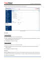
UPS/Information page of a PR1000LCDRTXL2Ua
The UPS/Information page shows information about the UPS:
Model: The model name of the UPS.
Firmware Version: The firmware version of the UPS.
Serial Number: The serial number of the UPS.
29
™
PowerPanel Business Edition
UPS Type: The type of the UPS. e.g. On-Line, Line Interactive or Sinewave Line Interactive.
Power Rating: The Volt-Amp rating and power rating (Watts) of the UPS.
Current Rating: The output current rating (Amps) of the UPS.
Voltage Rating: The input voltage range (Volts) of the UPS.
Frequency Rating: The input frequency range (Hz) of the UPS.
Battery Replacement Date: The date that the batteries were last replaced. This can only be set at the
time of battery replacement. This date should be set after the battery replacement. If this date has not
been set, it is recommended that this date should be set immediately. Once set, the software will alert
the customer when the battery age has reached 3 years.
NCL Outlet: The amount of the Non-Critical Load outlets.
LCD Firmware Version: The firmware version of the LCD screen on the UPS.
USB Version: The version of the USB chipset on the UPS.
Extended Battery Pack: The amount of extended battery packs connected to the UPS.
Installation Place: Clicking the Find it button will ask alarm to beep or indicators to blind in order to
inform users of the location. This helps users to identify the specific UPS at installation sites with multiple
UPS units.
Note: Not all models provide the same information. The information displayed will vary by model.
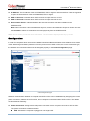
Configuration
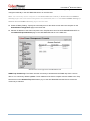
The UPS/Configuration page allows for customized UPS configurations to meet specific operational
requirements.
UPS/Configuration page of a PR1000LCDRTXL2Ua
30
™
PowerPanel Business Edition
Supplied Power
Voltage: Sets the output voltage which is supplied to the connected equipment.
Note: On some models belonging to the Paragon Tower series, this setting becomes configurable in
bypass mode and the changes require a restart to activate.
Frequency Working Mode: Smart App Online series supports two frequency modes: Followup and Fixed. In the Follow-up mode, the UPS supplies power based off of the utility frequency. If utility
frequency varies and is out of tolerance, the UPS supplies battery power with a fixed frequency to avoid
supplying the connected equipment an improper frequency. The fixed frequency depends on the utility
frequency detected as the UPS is powering up.
In Fixed mode, the UPS supplies power at a fixed frequency with no regard to utility frequency. When
the input frequency is unstable such as with power supplied by generators, set the UPS to fixed mode to
supply power with a stable frequency.
The UPS can be set to fixed mode if the equipment needs a different frequency from the utility power.
For example, the equipment is rated at 50 Hz but utility frequency is at 60 Hz.
Follow-up Tolerance: Sets the acceptable range of the output frequency on the Follow-up mode.
Fixed Frequency: Sets the fixed value of the output frequency on the Fixed mode.
Caution: The wrong frequency settings may damage the connected equipment. Make sure the selected
frequency is correct for the connected equipment. An alert warning message will remind you of the
following conditions:
The frequency mode has changed from the Follow-up mode to the Fixed mode, and the fixed
frequency is not equal to the utility frequency.
The frequency mode is Fixed mode and the fixed frequency is going to be changed.
ECO Mode: The UPS will enter bypass mode according to the utility voltage if it is in range of thresholds
or the utility frequency is within 3Hz of the utility frequency. If the utility voltage or the utility frequency
exceeds thresholds, the UPS will supply battery power to its loads.
If this threshold is set to 10% and the current utility voltage is 120 V, the UPS will enter bypass mode as
long as the utility voltage within the range of 108 V ~ 132 V. Once the voltage threshold is exceeded, the
UPS will supply battery power to its loads.
Caution: Once the UPS is allowed to enter the Fixed mode, Generator Mode or Manual Bypass when
the UPS is in the ECO mode, the UPS will leave ECO mode.
Users can configure exclusive days and exclusive time to for UPS when to not enter ECO mode.
Exclusive Days: Sets the days for UPS not to enter ECO mode.
Exclusive Time: Sets the time period for UPS not to enter ECO mode.
Power Failure Condition
When the utility power exceeds specific thresholds, the UPS will supply battery power to the connected
equipment.
Utility Voltage Upper/Lower Bound: Before utility power is provided to the UPS, the UPS will detect
whether utility voltage exceeds the threshold. If utility voltage exceeds the threshold, the UPS will supply
battery power to the connected equipment.
31
™
PowerPanel Business Edition
Output Voltage Upper/Lower Bound: Before the UPS uses utility power as its output power, the UPS
will detect whether utility voltage exceeds the threshold. If the utility voltage exceeds the threshold, the
UPS will supply battery power to connected equipment.
Note: High/Low Utility Voltage Threshold & High/Low Output Voltage Threshold settings only come
into effect after a restart of the UPS.
Frequency Upper/Lower Bound: When the utility frequency exceeds the threshold, the UPS will supply
battery power at a fixed frequency to the connected equipment.
Detected Sensitivity: When the UPS detects that utility voltage is out of range, the UPS will switch to
battery mode to protect the equipment plugged into the UPS. Low sensitivity has a wider voltage range
and the supplied power may vary more. The UPS switches to battery mode rarely and also saves more
battery power. The power from a fuel generator may cause the UPS to switch to battery mode more
frequently, and low sensitivity is recommended. High sensitivity allows the UPS to supply more stable
power to equipment but switches to battery mode frequently.
Power Restore
®
When a utility power failure occurs, PowerPanel Business Edition software may order the computer to shut
down and power off after the specified remaining runtime is met or if the battery capacity is low. After the
utility power is restored the UPS turns on automatically and supplies power to the computer. If the computer
BIOS is set to boot when power is restored the computer will automatically restart.
The following settings are used to configure the UPS restore behavior:
Automatic Restore: When this option is enabled, the UPS will restore output immediately when the
utility power is restored. When this option is disabled, the UPS will not restore output at that moment and
users have to turn it on manually.
Mandatory Power Cycle: When a shutdown sequence is initiated due to a power failure, the connected
computers may be ordered to shut down and the UPS will be also ordered to turn off after a time delay. If
the utility power is restored prior to the UPS shutting off, the UPS will still turn itself off. In this
circumstance, the utility power has restored, but the connected computers have shut down and the UPS
has turned off.
If the Mandatory Power Cycle option is enabled, the UPS will also turn off after a time delay, but it will
turn on again about 10 seconds later. The UPS has restarted and then all connected computers will boot.
Note: Most computers have the ability to boot when utility power is restored. Make sure this function is
supported and enabled in the system BIOS.
Recharged Delay: When the utility power is restored, the UPS will start to recharge until the specified
delay is expired before restoring output power.
Recharged Capacity: When the utility power is restored, the UPS will start to recharge until the
specified battery capacity is met before restoring output power.
Startup Delay: When the utility power is restored, the UPS will delay the restoration of output power.
This option can be used to stagger the startup time of multiple UPS to avoid overloading the utility power
32
™
PowerPanel Business Edition
circuit or power source. The Startup Delay option will take effect every time when the UPS is about to
restore power. This also includes the scheduling task.
Stable Utility Delay: When the utility power is restored, the UPS will delay switching to normal operation
from using battery power. If the battery capacity is lower than the Low Battery Threshold as power is
restored, the UPS will switch to normal operation immediately. This option can be used to prevent
frequent outage due to unstable utility power.
Restore Action: Sets the operating mode after utility power restores. If the Bypass option is selected,
the UPS will enter to bypass mode and supply power from the bypass module to connected equipments
when utility power restores. If the Online option is selected, the UPS will supply power from the UPS
modules to connected equipments when utility power restores. If the Standby option is selected, the UPS
will be off when utility power restores.
Bypass Condition
The Online UPS series supports the bypass function. When the UPS is in bypass mode, the utility power is
supplied directly to the connected equipment. To configure whether the UPS is allowed to enter or remain in
bypass mode in select from the following:
Qualification: This configures the qualifications the UPS uses to determine if it will enter bypass mode when a
UPS fault or overload occurs.
Valid Volt. & Freq.: If the utility voltage is in range of the voltage thresholds and the utility frequency
is in range of the frequency tolerance, the UPS will enter bypass mode. Otherwise the UPS will stop
supplying output power.
Valid Voltage: If the utility voltage is in range of the voltage thresholds, the UPS will enter bypass
mode. Otherwise the UPS will stop supplying output power.
Never Bypass: If this option is selected, the UPS will not enter bypass mode and will stop supplying
output power.
Mandatory: If this option is enabled, the UPS always enters bypass mode, due to a fault or overload,
even the utility voltage is outside of the normal range. Otherwise the UPS will stop supplying output
power.
Caution: Bad utility voltage while in bypass mode may damage the connected equipment.
Manually Execution: Determines whether to allow the UPS to enter Manual Bypass mode. If this Start
option is selected, the UPS will be forced to enter bypass mode.
Caution: Make sure that the UPS is not using generator power or converted power. When the UPS
enters bypass mode, the UPS will use input power to supply to equipment. The unstable frequency of the
input power may damage connected equipment.
Caution: If this option is enabled, the UPS can’t function in the Generator mode.
Voltage Upper/Lower Bound: When a UPS fault or overload occurs, UPS will determine whether to
enter bypass mode according to range of thresholds from utility power. If the utility voltage exceeds
thresholds, UPS will be forbidden to enter bypass mode and will stop supplying output power.
Overload: This configures the ability of the UPS to switch to bypass mode and supply utility power when
the output is overloaded. Without this enabled the UPS will stop supplying power when overloaded.
33
™
PowerPanel Business Edition
Bypass at Power Off: This determines whether the UPS will switch to bypass mode and supply utility
power when the UPS is switched off.
Battery
Prevent Excessive Discharge: When the UPS uses the battery to supply power for output, a deep
discharge with a low load can shorten the battery life. If this option is enabled, the UPS will stop
supplying power after discharging for 4 hours to avoid a deep battery discharge.
Energy Saving: When the utility power fails, the batteries will start discharging. If this option is enabled
and there is no output load, the UPS, will shut down to save battery power after discharging for 5 minutes.
The UPS will restart automatically and restore output after the utility power is restored.
Low Battery Threshold: When the UPS supplies battery power and the remaining capacity is lower than
this threshold, the UPS will sound an alarm.
Battery Test Period: The UPS will periodically perform the battery test to ensure the batteries are fully
functional.
Extended Battery Pack: Sets the amount of extended battery packs. This allows for an accurate
runtime estimate based upon the total number of batteries.
Boost Charge Period: Sets the period for UPS batteries being boost charged automatically and
periodically.
Discharge Duration Limit: Sets the duration to limit the battery discharging to avoid a deep discharge
excessively.
System
Cold Start: Sets the ability of the UPS to start in the absence of input power. When this option is
enabled the UPS can be turned on without having input power.
Short Circuit Recovery Detect: When the output of the UPS causes a short circuit, the output will turn
off immediately. If this option is enabled, the UPS will inspect the circumstance of the short circuit 3 times
in 30 seconds. If the short circuit is no longer present, the UPS will restore power. If the circumstance of
the short circuit still remains, the UPS will not supply power.
Utility Power Failure Alarm: If this option is enabled, the UPS will issue an audible alarm when the
utility power fails.
Overload Alarm Threshold: When the output load exceeds this threshold, the UPS will issue an audible
alarm.
Generator Mode: If the UPS is using a generator for its input power, this option should be enabled for
UPS to function normally. If this option is enabled, the UPS will be forbidden to enter bypass mode to
protect the powered equipment.
Caution: If this option is enabled, the UPS can’t function in the Manual Bypass mode.
LCD Back-light Saving: When no UPS button is pressed or no power event occurs during this delay,
the LCD screen will be turned off.
Wiring Fault Detecting: If this option is enabled, the UPS will detect if the UPS wiring is not grounded or
reversed. It is recommended to assure the UPS wiring has ground connection first. This option should be
enabled if the UPS wiring has ground connection.
34
™
PowerPanel Business Edition
Dry Relay Function: This configures the power condition for the UPS dry relay to function when the
selected condition occurs. Refer to UPS manual for further information about advanced UPS dry relay
utilization. The Dry Relay Function provides the following power conditions:
Utility Failure: The utility power fails and the UPS is using the battery power.
Low Battery: The battery capacity is low and cannot support the connected computers if they
require a shutdown.
Alarm: The UPS is issuing an audible alarm due to a warning event, such as Overload
Bypass: The UPS has switched to bypass mode due to an overload or UPS fault.
UPS Fault: The UPS may be malfunctioning due to an internal problem, such as an inverter fault,
bus fault or overheating.
Redundant Quantity: Sets the quantity of UPS modules to be power redundancy. This power
redundancy can provide the fault-tolerant protection against failures of equivalent UPS modules. UPS
should avoid exceeding output load from whom deducted the power redundancy; otherwise UPS cannot
afford the equivalent fault-tolerant protection as user’s desire.
NCL Outlet
NCL stands for Non-Critical Load. Under the following conditions, the UPS will turn off the NCL outlet to
conserve battery power and maximize battery runtime for the remaining outlets:
Turn Off Threshold: When supplying battery power, the UPS will power off this NCL outlet if the
remaining battery capacity is lower than this threshold.
Turn Off Delay: When supplying battery power, the UPS will power off this NCL outlet after this delay
time is met.
Turn On Delay: When the utility power is restored, the UPS will restore the output of this NCL outlet
after the delay time is met. This prevents excessive power consumption caused by all the connected
equipment starting at the same time.
Note: Not all models provide the same configurations. These configurations will vary by model.
Diagnostics
The UPS/Diagnostics page provides the ability to verify that the UPS can supply adequate battery runtime
for the connected computers to shutdown properly. Perform a complete runtime calibration to ensure an
accurate estimate of the runtime for the connected load. The buzzer can be tested to ensure that the UPS
can issue an alarm and that the indicator lights will display properly if requested by the UPS.
35
™
PowerPanel Business Edition
UPS/Diagnostics page
Battery Test
The Battery Test performs a battery test to verify that the batteries are good, and shows information
including the result and the date of the last battery test. Click the Initiate button to begin a battery test.
Performing a battery test is prohibited when the Frequency Working Mode option is set to fixed.
The results will be reported after a battery test completes:
Last Test Date: The date the last battery test was performed.
Last Test Result: The result of the last battery test:
Passed: The battery performed normally during the test.
None: The UPS has never performed the battery test.
Failed: The battery test resulted in failure.
Follow the below steps if the battery test fails:
Repeat the battery test and replace the batteries if the test fails again.
Contact CyberPower for assistance if the battery test fails after the batteries have been replaced.
Runtime Calibration
36
™
PowerPanel Business Edition
The Runtime Calibration ensures the runtime estimate is accurate with the current load. The results show
the runtime, the result, and the date of the last calibration. When a runtime calibration is initiated, the
connected equipment will be run on battery power until the batteries are completely discharged. The
batteries will be then automatically recharged following the calibration.
Users can click the Start button to initiate a runtime calibration. Click the Cancel button to interrupt the
runtime calibration. The result will be reported after a calibration is finished or canceled:
Estimated Runtime: The estimated runtime of the batteries.
Last Calibration Result: The result of the last runtime calibration.
Passed: The runtime calibration completed and the batteries are good.
None: The UPS has never performed a runtime calibration.
Failed: The UPS failed during the runtime calibration.
Canceled: The calibration was interrupted.
Last Calibration Date: The date the last runtime calibration was performed.
Note: It is recommended to perform at least one calibration every 3 months.
Note: A complete calibration causes the battery capacity to deplete, Ensure the UPS is recharged
completely after performing a calibration.
Alarm Test
The Alarm Test allows users to verify that the alarm can beep normally and shows the date of the last test.
Click the Initiate button to begin an alarm test.
The details will be reported after an alarm test is complete:
Last Processing Date: The date the last alarm test was performed.
Indicator Test
Indicators on the front panel or on the LCD screen are used to present the UPS status. Once the indicators
are malfunctioning, users won’t know the current UPS status. The Indicator Test allows users to ensure
whether indicators blink normally. Click Initiate button to begin an indicator test.
The details will be reported after an indicator test is complete:
Last Processing Date: The date the last indicator test was performed.
Load
The UPS supplies power to generic equipment and shutdown-protected computers that connect to native
outlet sockets of UPS or extended PDU. The UPS/Load page provides detailed information about connected
loads and the extended PDU.
37
™
PowerPanel Business Edition
UPS/Load page
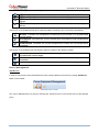
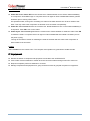
Manage Loads
Users can manage connected loads that include generic equipment and computers from the Load
Management page. A UPS and named PDU tabs whose lists contain connected loads. All connected loads
can be listed with detailed information including the name, location, contact, and what type of outlet the
equipment is plugged in from the list.
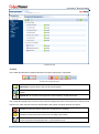
Plug a load on UPS or PDU. Select the UPS or one named PDU tab, click the target outlet from the list,
and ensure whether the outlet from the Outlet Preview is correct. If you want to plug a computer that
has been installed PowerPanel Business Edition Client software for shutdown protection in a UPS or
PDU, click Yes on the Shutdown Protected option, enter the IP address of computer and then click the
Apply button to complete; If you want to plug generic equipment that have not been installed or cannot
install PowerPanel Business Edition Client software for shutdown protection in a UPS or PDU,
click No on the Shutdown Protected option, enter the name and optional information for the equipment
and then click the Apply to complete.
Clicking the reversed triangle icon helps to input IP address of computer easily and quickly. A drop-down
list shows the search result of available computers that have been installed PowerPanel Business Edition
Client software. Clicking the rotating arrow will start a new search to update the search result. .
Change the load information. Click the target load you wish to change from the list. Update the data in
editable fields and then click Apply to complete.
38
™
PowerPanel Business Edition
Move load’s plug to another outlet. Click the target load you want to move from the list. If you want to
move the load’s plug from one outlet to another one, assign the target outlet in the Outlet option; if you
want to move the load’s plug from UPS to PDU, from PDU to UPS or between PDUs, assign the target
UPS or PDU in the Device option, and then click Apply to complete.
Unplug the load from UPS or PDU. Click the target load you wish to unplug from the list. Click No on
the Enabled option and then click Apply to complete.
The PowerPanel Business Edition Client software can be installed on computers to benefit shutdown
protection in order to ensure a proper shutdown in the extended power outage event and control demands in
UPS and extended PDU.
Assigning a correct outlet is important. The Outlet option must be configured to match the actual equipment
plugged into the UPS outlet. Depending on the UPS configuration of specific models with NCL outlets, these
outlets will lose power before the entire UPS is shutdown. The Agent will request Client computers powered
by these outlets to perform a shutdown to avoid data loss because of the power outage.
Note: The Client computer name will be displayed in gray if communication with the Client computer is not
established.
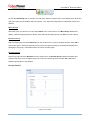
Manage PDU and ATS
When the PDU or ATS connects with the UPS as extensible outlets, users can manage these PDU/ATS in
the list on this page. A named PDU or ATS tab whose list contains connected generic equipment and
computers will be created due to the connection with PDU/ATS from UPS, and removed due to the
disconnection with PDU/ATS from UPS.
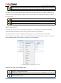
Install a PDU on UPS. Select the Install PDU from the dropdown menu by clicking the Power
Distribution shortcut on the list. If the PDU has network function, select Network from the PDU Type
option, enter the network address of PDU and assign the target outlet of UPS outlet that PDU had
plugged in; if the PDU is generic PDU without network function, select the Generic from the PDU Type
option, select a PDU model from the Model option and enter a name for the PDU. Click Apply to
complete.
Install an ATS on UPS. Select the Install ATS from the dropdown menu by clicking the Power
Distribution shortcut on the list. Assign the target UPS outlet that the ATS has plugged in, select the
target input source of ATS to connect with UPS and enter the network address of ATS. Click Apply to
complete.
Move PDU/ATS’s plug to another UPS outlet. Select the target PDU/ATS tab you want to move.
Select Configure PDU/ATS from the drop-down menu by clicking the Power Distribution shortcut on
the list and select another UPS outlet on UPS outlet option. Click Apply to complete.
Uninstall the PDU/ATS from UPS. Select the target PDU/ATS tab you want to uninstall. Select
Configure PDU/ATS from the dropdown menu by clicking the Power Distribution shortcut on the list.
Select Disconnect PDU/ATS with UPS option and click Apply to complete.
Note: When a PDU/ATS is uninstalled from the UPS, all loads include generic equipment and computers
on this PDU/ATS will be removed; computers will also no longer keep communication with the UPS.
39
™
PowerPanel Business Edition
Note. PDU or ATS may be configured in the Power/Configuration page of PPBE Client’s web interface
directly. A named PDU/ATS tab with tip “Does PDU/ATS connect to UPS?” will appear automatically to
inform you to ensure it.
Note. PPBE did not allow ATS to connect two input sources to one single UPS.
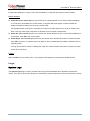
Client computer is printed in gray when the communication is not established
The details in list are described as following:
#: Indicates which power outlet of the UPS or PDU is supplying power to the connected equipment.
Bank: The bank type of the power outlet on the UPS, e.g. NCL, CL or Surge.
Name: The name of the power equipment.
Location: Where the power equipment is located.
Contact: Who to contact about this power equipment.
IP Address: The IP address of the computer that installed PowerPanel Business edition Client software.
In UPS tab, a PDU with network function also shows its own IP address.
Agent searches all Clients on local network.
Power
(The content in this section is only applicable to the Client.)
The Client can interact with a UPS or a PDU through a network interface. If the UPS has no remote
management card, the Agent can be installed on a single computer which is using a USB or a serial
connection directly to the UPS in order to establish the network connection to the Client.
40
™
PowerPanel Business Edition
Information
Power/Information page
The Power/Information page shows information about the UPS/PDU/ATS which supplies power to the
Client computer. When the Client establishes with a PDU which is connected to a UPS, Information page
displays the information about the PDU and the UPS individually. Information illustrates as follows:
Device Type: The type of the UPS/PDU/ATS, e.g. UPS/PDU/ATS.
Model: The model name of the UPS/PDU/ATS.
Serial Number: The serial number of the UPS/PDU/ATS.
Firmware Version: The firmware version of the UPS/PDU/ATS.
UPS Type: The type of the UPS. e.g. On-Line or Line Interactive.
PDU Type: The type of the PDU. e.g. Monitored or Switched.
ATS Type: The type of the ATS. e.g. Monitored or Switched.
Power Rating: The Volt-Amp rating and power rating (Watts) of the UPS.
Current Rating: The output current rating (Amps) of the UPS/PDU/ATS.
Voltage Rating: The output voltage rating (Volts) of the UPS/PDU/ATS.
Frequency Rating: The output frequency rating (Hz) of the UPS.
Battery Replacement Date: The date that the batteries were last replaced.
NCL Outlet: The amount of NCL (Non-Critical Load) outlets in the UPS.
Extended Battery Pack: The number of extended battery packs connected to the UPS.
Name: The name of the UPS/PDU/ATS.
Location: Where the UPS/PDU/ATS is located.
Contact: Who to contact about the UPS/PDU/ATS.
41
™
PowerPanel Business Edition
MAC Address: The MAC address of the UPS RMCARD, PDU or Agent’s network interface.
IP Address: The IP address of the UPS RMCARD, PDU or Agent’s network interface. Click the hyperlink
to open the web interface of the UPS RMCARD, PDU or Agent.
UPS on Source A: Indicates which UPS connects to input source A of ATS.
UPS on Source B: Indicates which UPS connects to input source B of ATS.
Environment Sensor: Indicates whether the environment sensor has been installed on the
UPS/PDU/ATS.
Note: When the sensor cannot be detected anymore, it will be annotated No Response. Users can click
the Uninstall to reflect it if it had been removed physically from the UPS/PDU/ATS.
Note: Not all models provide the same information. The information displayed will vary by model.
Configuration
In order for computers which have been installed PowerPanel Business Edition Client software to be aware
of the state and get shutdown protection from the power event of UPS or PDU, the correct connection type,
the address and connected outlet must be assigned properly in the Power/Configuration page.
Power/Configuration page
Network communication between a computer and UPS or PDU can be established by assigning the correct
power connection, address of UPS or PDU, and a computer connected outlet of UPS or PDU. The details
are described as following:
Power Connection: Assigns the actual power connection how a computer connects to UPS or PDU.
The power connections include as below:
UPS: Indicates the computer is plugged in one single UPS.
42
™
PowerPanel Business Edition
ATS: Indicates the computer is plugged in an ATS.
Network PDU: Indicates the computer is plugged in one single PDU with network function.
UPS with Network PDU: Indicates the computer is plugged in a network PDU, which is a power
extension from the UPS.
UPS with Generic PDU: Indicates the computer is plugged in a generic PDU, which has no network
function and is a power extension from the UPS.
UPS Address: Assigns the network address of the UPS. Enter the IP address or use the pull down to
show the device list and select a device address from the list. Clicking the refresh button (the icon with
the rotating arrow) causes to search the network to update the results. If a UPS communicates with a
computer that has been installed PowerPanel Business Edition Agent, assign the IP address of the
computer as the UPS network address. This option appears when power connection is set up making
computer connect to UPS directly.
When the power of a computer is configured to connect to an ATS, two UPS addresses will appear to be
assigned. Any one of input source of ATS is being supplying power by a UPS, the network address of
UPS should be assigned. An UPS address, which is set blank, indicates that the input source of ATS did
not connect to an UPS.
Move the cursor over the target address to display details about the device
The computer searches the device with the least uptime to be a default device after an installation. One
available outlet will be assigned to connect automatically with the computer. If no outlet is available, the
first critical-load outlet will be assigned to be used by a computer.
The uptime of the devices indicates the length of time that the device has been functioning. When the
computer scans the network, the device with shortest uptime will be marked a yellow star icon. You can
press the Reset button for 1 second to reset the uptime of device to have the top priority. Do not press
the reset button for more than 4 seconds. Otherwise, it will be recognized as a complete configuration
reset demand.
Clicking the refresh button to search all devices again on the local network
43
™
PowerPanel Business Edition
PDU Address: Assigns the network address of the PDU. Enter the IP address or use the pull down to
show the device list and select a device address from the list. Clicking the refresh button (the icon with
the rotating arrow) causes to search the network to update the results. This option appears when power
connection is set from computer to network PDU directly.
ATS Address: This option appears when the power of a computer is configured to connect to an ATS.
PDU Name: Selects the target generic PDU from list. After the UPS with Generic PDU of the Power
Connection option is selected and entering a UPS address, the computer will fetch the list of installed
PDU from UPS. If the list is empty, then you have to install the PDU in UPS/Load page of PowerPanel
Business Edition Agent. This option appears when power connection is set from the computer to a PDU
that is an extension power of the UPS, which is controlled by PowerPanel Business Edition Agent.
UPS Outlet, PDU Outlet and ATS Outlet: Indicates which power outlet of the UPS or PDU/ATS is
supplying power to the computer that has been installed PowerPanel Business Edition Client software.
The outlet list will be updated after entering a network address of UPS or PDU/ATS. Outlet preview will
be shown with a selected outlet accordingly for assisting to verify whether the computer is connected to
the proper outlet.
The Identify button is only visible after the Client has established communication with the network PDU;
the identification function helps to identify which outlet has the connected equipment. The PDU will blink
the outlet number on the LCD screen to verify the actual connection on the PDU matches when
the Identify button is pressed.
Troubleshooting the Client’s inability to communicate with the power device:
Verify the network address is correct.
Verify the network configuration for the UPS or PDU is correct. The Power Device Network Utility tool
can be used to configure the network configuration. The tool can be installed from the tools folder on the
installation CD.
Verify that the settings in the Security/Authentication page are correct and match the settings of the
device. See Security/Authentication for more details.
Verify the port in the Security/Network page is matched with settings of PowerPanel Business Edition
Agent.
Check that the network status of computer and devices.
Verify that firewall settings. Port 3052(UDP/TCP), port 53568(TCP), port 162(UDP) and port 53566(UDP)
should be unblocked. The computer communicates with the power device on these ports. The installer of
®
PowerPanel software will automatically configure Windows firewall to allow PowerPanel Applications to
access through firewall.
The following messages may be displayed:
Network communication can’t be established. Make sure the device network configuration is
accurate. The computer never establishes the network communication with device due to improper
network configuration on the device. See Troubleshooting the Client’s inability to communicate with
the power device section for more details to resolve this condition.
44
™
PowerPanel Business Edition
Network communication lost. Make sure the devices network configuration is accurate. The
network communication between the computer and the device has been lost. See Troubleshooting the
Client’s inability to communicate with the power device section for more details to resolve this
condition.
Can’t fetch the outlet information. Make sure that the device local communication is connected.
The USB cable or serial port between the computer that installed PowerPanel Business Edition Agent
and the UPS may not be connected, or the UPS RMCARD could be plugged improperly. Verify the local
communication is connected property.
The assigned outlet is in use. Please choose another outlet. Indicates the assigned outlet is in used
by another piece of equipment or computer. In order for the computer to perform a graceful shutdown, it
is recommended to change to another outlet which is not in use.
The assigned outlet is off. Please choose another outlet. The outlet assigned is not supplying power,
and the wrong outlet may have been identified. Verify the correct outlet is selected. .
The assigned outlet has a turn off pending. The system will be shutdown soon. The outlet being
used by the computer will be switched off and will stop supplying power to the computer after the delay is
finished.
System may not shutdown properly because the off-delay is too short. According settings in PDU
depends on connected outlet and computer to be aware of having insufficient time for the computer to
perform a complete shutdown. The off-delay may be setup to extend in the PDU web interface.
This PDU has been set to connect with the UPS (X.X.X.X). When the computer detects that the PDU
has been set to connect with a UPS during the computer attempts establish communication with a PDU,
the computer will update the device settings and inform users of the connection from PDU to UPS.
UPS address is necessary for shutdown protection on computer when power outage. This warning
note the network address of UPS is set blank; the network address of UPS should be assigned to get
power protection.
PDU address is necessary for shutdown protection on computer before outlet is turned off. When
power of computer is configured to connect to a PDU, the network address of PDU is set blank. The
network address of PDU should be assigned to get power protection prior to a turning-off outlet.
Event Action
An event is generated when the UPS/PDU/ATS encounters specific power conditions. The PowerPanel
®
Business Edition software can be configured to respond to specific events and perform actions based on the
event. These actions include notification, command execution and computer shutdown.
If a Client establishes with a PDU which is connected to a UPS, the Client can generate actions in response
to events from the PDU or the UPS.
Events
®
When an event occurs, PowerPanel Business Edition software can notify administrators, execute a
command and initiate a computer shutdown sequence. The Event Action/Events page lists events and the
45
™
PowerPanel Business Edition
action settings for the events. The severity of each event is marked by a symbol. Severe level (
) indicates
users must be alerted and the computer shut down to avoid an improper shutdown. Warning level ( )
indicates a warning and users should be notified when it occurs. If a warning condition persists, a system
shutdown may be imminent. Information level (
) indicates the state of the UPS or that the utility power
condition has changed.
Event Action/Events page in the Agent
After selecting an event, the event will become configurable. Configure all of the action settings for the
selected event and apply to save the settings.
The clicked event item will be configurable.
Use these parameters to configure actions for individual events:
Notify
The administrator can be notified when an event occurs. See Event Action/Notification Recipient page for
more details about the notification methods and recipient assignment.
Initiated: Determines whether to send a notification or not and sets the notification delay. If the event is
cleared within the notification delay, the notification of the occurrence and the event cleared notification
will not be sent.
46
™
PowerPanel Business Edition
Repeat: Determines whether to send one additional notification after the initial notification. Only events
which are of severe-level and warning-level type support a repeat notification.
Command
A command will be executed when an event occurs.
Initiated: Determines whether to execute a command and sets the delay for the command execution. If
the event is cleared within the command execution delay, the command for this event and the
corresponding event will not be executed.
Duration: Sets the estimated time for the command to complete. If the event requires the computer to
shut down, this delay provides time for commands and scripted actions to complete before the shutdown
is initiated.
File: Sets a command file to be executed when an event occurs. Shell scripts for the command file uses
"cmd" as the filename extension. For more information about shell scripts read the detailed description in
®
the "default.cmd" file in the "extcmd" folder in the PowerPanel Business Edition installation directory.
®
Customized shell scripts must be saved in the "extcmd" folder in the PowerPanel Business Edition
installation directory. The command file will be listed on the Command/File list and can be executed
when the power event occurs.
Note: The command file name will be displayed in italics if the command file which had used cannot be
found in the “extcmd” folder.
The following environment variables can be placed to external commands to identify which event and which
stage to be executed.
%EVENT_STAGE%: Indicates what stage of firing event to execute the commands. When an event
occurred and enters OCCUR stage, the assigned commands will be executed. When an event is ended,
the variable will be FINISH and the assigned commands will be executed.
%EVENT%: Indicates which event is fired to execute the commands.
%EVENT_CONDITION%: Indicates which the detailed event condition of a firing event.
%MODULE_NO%: Indicates which UPS module on a firing event. This variable is used on Modular UPS
models.
Users can know how to configure commands from the following table which lists all details of %EVENT% and
%EVENT_CONDITION%.
%EVENT%
ENTER_BYPASS
BATTERY_EXHAUSTED
EMERGENCY_OFF
BATTERY_FULL
SHUTDOWN
BYPASS_FAILURE
CAPACITY_INSUFFICIENT
LOSS_REDUNDANT
ABNORMAL
%EVENT_CONDITION%
Event Name
Enters bypass mode.
The battery has been
exhausted.
EPO is active.
Battery is fully charged.
Shutdown initiated.
Bypass power is failure.
Inverter capacity is insufficient.
Power redundancy is not
enough.
UPS is abnormal.
47
™
PowerPanel Business Edition
NO_NEUTRAL
WIRING_FAULT
FATAL_ABNORMAL
4
OUTPUT_OVERLOAD
BYPASS_OVERLOAD
MODULE_OVERLOAD
SHORT_CIRCUIT
1
MODULE_RECTIFIER_OVERHEAT
1
MODULE_INVERTER_OVERHEAT
1
MODULE_INVERTER_PROTECTED
BATTERY_REVERSED
BYPASS_SEQUENCE_ERROR
COMMUNICATION_FAILURE
FAULT
Input is no neutral.
Site wiring fault.
UPS is fatal abnormal.
Output is overloaded.
Bypass is overloaded.
Module is overloaded.
Output circuit-short.
Module rectifier is overheated.
Module inverter is overheated.
Module inverter is protected.
The polarity of battery is
reversed.
The phase sequence of
bypass is wrong.
4
LOST_IN_LOCAL
3
LOST_IN_NETWORK
Local communication lost.
Network communication lost.
GENERIC_FAULT
BYPASS_FAN_FAULT
BYPASS_FAULT
1
MODULE_RECTIFIER_FAULT
1
MODULE_INVERTER_FAULT
1
MODULE_FAN_FAULT
UPS is faulty.
Bypass fan is faulty.
Bypass is faulty.
Module rectifier is faulty.
Module inverter is faulty.
Module fan is faulty.
Battery is not present.
Available runtime is
insufficient.
Utility power failure.
LOST_IN_LOCAL
Local communication lost in a
power event.
Network communication lost in
a power event.
Remaining runtime will be
exhausted.
The output power is going to
stop soon.
Input is near overload.
Input is overload.
Shutdown time is in
insufficient.
ATS is faulty.
Inputs both fail, ATS doesn’t
switch input source.
Switch to redundant input
source of ATS automatically.
Redundant input source of
ATS is power failure.
Environment sensor is no
response.
Environment temperature is
overheated.
Environment temperature is
undercooled.
Environment humidity is over
wet.
Environment humidity is
overdried.
4
NO_BATTERY
RUNTIME_INSUFFICIENT
UTILITY_FAILURE
URGENT_COMMUNICATION_
4
FAILURE
LOST_IN_NETWORK
RUNTIME_WILL_EXHAUST
OUTPUT_WILL_STOP
INPUT_NEAR_OVERLOAD
2
INPUT_OVERLOAD
SHUTDOWN_TIME_
2
INSUFFICIENT
5
ATS FAULT
5
ALL_SOURCE_FAILURE
2
CURRENT_SOURCE_FAILUR
5
E
REDUNDANT_SOURCE_FAIL
5
URE
6
ENV_SENSOR_LOST
ENV_SENSOR_OVERHEAT
6
ENV_SENSOR_UNDERCOOL
ENV_SENSOR_OVERWET
ENV_SENSOR_OVERDRY
6
6
6
48
™
PowerPanel Business Edition
1
: This event only occurs for the Modular UPS in Agent.
2
: This event only occurs for the PDU in Client.
3
: This event only occurs in Client.
4
: This %EVENT% variable must come with a %EVENT_CONDITION% variable.
5
: This event only occurs for the ATS in Client.
6
: This event only occurs for the environment sensor for UPS/PDU/ATS in Client.
Shutdown
Initiate a shutdown sequence when an event occurs. A shutdown sequence is only initiated by events which
are of severe-level and warning-level type.
Initiated: Determines whether to request the computer to be shut down and the delay before initiating
the shutdown sequence. The shutdown will be canceled if the event is cleared during this delay time. The
minimum delay time to initiate shut down is based on the time set for the execution of the other actions to
complete. This includes the notify delay time, command delay time and command execution time.
As
This feature is used to apply identical settings to the particular event within the same category (Severe,
Warning, and Information). Once the As field of one event have been assigned, the settings of this event will
use the assigned event’s settings. The settings of this event will match with an assigned event’s.
The setting for the Local communication lost event would be copied from the settings of the UPS is faulty event.
Event List
The Event List displays power events. The events displayed vary depending on whether they are listed in
Agent or Client and which UPS/PDU/ATS is providing the events.
Local communication lost in a power event. Communication with device has been lost during a power
event.
Communication between the Agent and the UPS using the USB or serial cable has been lost during a
power failure.
Batteries are not present. Batteries are not present, the UPS cannot provide battery power in this
condition.
Available runtime is insufficient. There is not sufficient runtime for a complete shutdown even if battery
has fully recharged.
This event will occur if the UPS has insufficient runtime (based off of the necessary shutdown time in the
Event Action page) for the Agent computer and all Client computers to shut down completely even if the
49
™
PowerPanel Business Edition
batteries have fully charged. An excessive load or long shutdown time may cause this event. Reduce
some UPS load or set a more accurate shutdown time to avoid this event occurrence.
Enters bypass mode. Entering bypass mode, battery power protection will no longer be provided.
Utility power failure. Utility power failure, battery power will be supplied.
Remaining runtime will be exhausted. Remaining runtime will be exhausted and is not sufficient for a
complete shutdown.
When the UPS switches to battery mode due to a power event, the battery power will be supplied to
Agent computer and all Client computers in order to shut down completely. If battery power consumption
continues, the remaining runtime will be exhausted. Agent and all Client computers should start a
shutdown procedure immediately.
The Agent postpones the shutdown until the Clients computers completes the shutdowns; if the
remaining runtime is insufficient for Agent to perform a complete shutdown prior to the UPS turning off,
the Clients will shutdown first to ensure sufficient time for Agent to shut down completely.
Note: This event usually indicates that the Agent and Client risked losing battery power, they will have a
tolerance of 2 minutes to avoid crashing due to a UPS turning off.
Battery test is processing. A battery test is active in order to verify that battery power can be provided
normally.
Output voltage is being boosted. Output voltage is being boosted from a lower level.
The UPS is receiving utility power with low voltage and raising the voltage to a proper level for operating
the connected equipment.
Output voltage is being bucked. Output voltage is being bucked from a higher level.
The UPS is receiving utility power with high voltage and is lowering the voltage to a proper level for
operating the connected equipment.
Calibration initiated. Calibration was initiated, the battery runtime will be evaluated.
A schedule has initiated. A schedule has initiated, the system may be shutdown.
Battery is fully charged. Battery has fully charged. The capacity of battery is full.
Shutdown initiated. Shutdown process initiated.
A shutdown process has initiated, and the system will shut down or hibernate.
ECO is active. The UPS is in ECO mode.
The UPS switches to bypass and starts to monitor whether the utility voltage and utility frequency is in
range of the thresholds.
The battery has been exhausted. Battery is exhausted and UPS stops the output.
EPO is active. EPO was activated; the UPS output power was turned off immediately.
EPO (Emergency power off) is intended to allow the administrator to have a method of immediately
turning off output power from the UPS.
Bypass power is failure. The condition of bypass power is out of regular range or blackout. In this
condition, the UPS will shut down and never enter the bypass mode once UPS is faulty.
Inverter capacity insufficient. UPS did not have enough capacity of inverter’s power to enter line mode
from bypass mode.
50
™
PowerPanel Business Edition
Power redundancy is not enough. The quantity of UPS module has not enough to be redundancy
completely and the fault-tolerant ability was reduce or lost completely.
Power redundancy provides additional protection against failures of UPS modules. If one module has a
fault, the other module will take over. This event will occur when the load consumption are exceeded to
use extra power that belong to redundant power, some UPS modules are faulty or manual shutdown.
UPS is abnormal. UPS is working abnormally due to power conditions that include as below:
Input is no neutral. The neutral wiring is not connected well.
Site wiring fault. The wiring is reversed or not grounded.
UPS is fatal abnormal. UPS is working abnormally due conditions includes as following list that may
cause UPS shutdown and no longer supply power soon or even immediately.
Output overload. Power consumption exceeds the power rating of UPS. If the overload is sustained,
the UPS will be stopped from operation.
Bypass overload - Output is overloaded in bypass mode.
Module overload - One of UPS module is . If the UPS module overload is sustained, the UPS
module will be protected from operation.
Output short circuit. Output circuit is shorten and causes UPS to stop supplying output power.
Module rectifier overheats. The internal temperature of one module rectifier exceeds the normal
rating.
Module inverter overheats. The internal temperature of one module inverter exceeds the normal
rating.
Module inverter protected. A module inverter has been protected and stops operating. The module
inverter may be faulty or fatal abnormal.
Reversed battery connection. The connection between UPS and battery is wrong on electrical
polarity.
Bypass phase sequence error. The sequence of phases is different between utility and bypass.
Communication lost. Communication between the UPS and computer has been lost. Computer cannot
have good communication with the UPS via USB, serial port or network, that conditions includes:
Local communication lost. Communication between the UPS and computer via USB or serial
cable cannot establish or was lost.
Network communication Lost. Software cannot establish communication with UPS or PDU on the
network or established network communication has been interrupted.
UPS is faulty. UPS has malfunctioned in internal. UPS may not be operating as user’s desire and
cannot afford power protection. Conditions include:
Bypass Fan fault.
Bypass Fault.
Module Rectifier Fault. One of module rectifier is faulty; this module will stop supplying output
power.
Module Inverter Fault. One of module inverter is faulty; this module will stop supplying output
power.
Module Fan Fault. One of module fan has been malfunctioned.
51
™
PowerPanel Business Edition
Note: Batteries are not present and A schedule has initiated events are only available in the Agent.
More events are available for the Client:
The output power is going to stop soon. Output power will stop due to power event or user
commands. When an UPS or a PDU is about to stop supplying the power to a Client computer, the Client
will be notified. The Client will shut down the hosted computer.
Cannot establish network communication with Power Device. The communication with Power
Device has been lost.
The Client cannot establish communication with the UPS/PDU/ATS on the network or established
communication has been interrupted.
Network communication lost with UPS in a power event. The communication with UPS has been lost
after a power event occurred.
When the utility power becomes abnormal and the UPS is using the battery to supply power, loss of
network communication between the Client and the UPS causes the Client to generate a critical priority
event because it cannot respond to changes in the status of utility and battery power.
More events are available for a PDU in Client:
Input is near overload. A PDU is near an overload condition.
The load level is near the maximum safe load for the PDU.
Input is overloaded. A PDU is in an overload condition.
The maximum safe load has been exceeded and the PDU is in an overload condition.
Shutdown time is insufficient. System shutdown time is insufficient.
After communication with the PDU is established and the outlet assignment is set up, the Client will
detect whether the connected outlet has sufficient time to allow for a shutdown. A sufficient shutdown
time for the Client computer requires at least the sum of the Necessary shutdown time option and
shutdown delay time as configured in the The output power is going to stop soon event.
More events are available for an ATS in Client:
Inputs both fail, ATS doesn’t switch input source. ATS doesn’t switch the source due to both input
sources are power failure.
When the current source of ATS is power failure, ATS attempts to switch to another source which is
functioning well. If both sources of ATS are power failure at the same time, the ATS cannot switch to
another source.
Switch to redundant input source of ATS automatically. When the current source of ATS is power
failure and another redundant source is functioning well, ATS will switch to the redundant source to
afford the power to its load.
Redundant input source of ATS is power failure. The current source of ATS is functioning well, but
the redundant source is power failure. In this situation, once the current source is power failure, ATS
cannot switch to redundant source to afford power to its load.
52
™
PowerPanel Business Edition
More events are available for the environment sensor within UPS/PDU/ATS in Client:
Environment sensor is no response. Environment sensor of the UPS/PDU/ATS has no response.. The
sensor may be malfunction or removal from the UPS/PDU/ATS.
Environment temperature is overheated. The temperature is measured by the sensor exceeds the
high threshold.
Environment temperature is undercooled. The temperature is measured by the sensor violates the
low threshold.
Environment humidity is over wet. The relative humidity is measured by the sensor exceeds the high
threshold.
Environment humidity is overdried. The relative humidity is measured by the sensor violates the low
threshold.
Notification Recipient
The Agent and Client can send notifications to multiple recipients in various ways, including Windows Alert
Messages, Instant Messages and Mobile phone text messages (SMS). The Notification Recipient page
lists all recipients in the recipient list and displays all defined notifications and whether the notification is
active.
Event Action/Recipient page
Recipients can be managed as follows:
53
™
PowerPanel Business Edition
Add a new recipient: Click the New Recipient to have the blank notification recipient fields or use the
data from a selected recipient. Enter all required data and click the Add button to add a new recipient to
the list.
Modify the recipient: Select the recipient you wish to modify. After entering in the new data, click the
Apply button to complete.
Remove the recipient: Select the recipient to remove from the recipient list, and then click Remove to
complete the recipient deletion.
The recipient detail settings and descriptions are explained below:
Active: States if the recipient is active.
Language: The language to which the recipient prefers. The notification sent to this recipient uses this
language to display content.
Recipient Name: The name of the recipient. The recipient name must be unique.
E-mail Address: The E-mail address of the recipient.
XMPP Account: The XMPP Instant Messaging account of the recipient. See Event Action/Settings for
more details about XMPP.
WLM Account: The Windows Live Messenger Instant Messaging account of the recipient.
Computer Username: The computer user account name which is used to receive the windows alert
messages. Due differences in the Messenger Service of different versions of Windows, please refer to
the descriptions below:
®
If PowerPanel Business Edition and the recipients are on Windows 2000, Windows 2003 or
Windows XP and or on a different computer, the service will work normally. The recipient on the
remote computer should be formatted as Server name/Users name.
®
If PowerPanel Business Edition and the recipients are on Windows Vista, Windows Server 2008
or Windows 7, and then the alert messages will only be sent to a local user account on the
®
computer running PowerPanel Business Edition.
®
Note: Computer Name filed and Alert column are only available on the PowerPanel Business Edition
which installed on Windows. On Linux, if Linux Message service is activated, the message will be sent to
all users on the computer.
Mobile Phone: The mobile number of the recipient to receive the mobile text message. It must contain
the country code.
Activation Day: Configures the days on which recipients can receive the notification. Users can define
the specific ways to notify the assigned administrators on different days.
Activation Time: Configures the time which recipients will receive the notification. Users can define the
specific ways to notify the assigned administrators during different times.
Enabled: Displays which notification(s) are active for the recipient.
Test: Sends the notification in accordance with current settings in order to verify the function. The
service can be tested only when the corresponding service on the Event Action/Settings page is
configured as activated.
54
™
PowerPanel Business Edition
Plan: The dots and line indicates the specific days and time to send a defined notification to the recipient.
When an event occurs at the activated time of the activated days, the notification will be sent to
recipients.
The dots and the line indicate the specific time and day of the week to notify the recipient of the event
Action Settings
Settings page allows for configuration of various event actions, including the necessary shutdown time of
the hosted computer.
After configuring all of the action parameters, and applying the settings, the Verify button can be used to
verify whether the user’s configurations are correct. To test whether a notification is configured properly and
a recipient can receive the notification successfully, use the Test function on the Event Action/Notification
Recipient page.
Each action has its own Activate option to specify whether to use the service to send a notification. If No is
checked, the Verify button and the corresponding Test function will be disabled. The column displayed in
the recipient list will be marked gray to indicate that action is disabled.
Shutdown
Necessary shutdown time: This setting will set the amount of time which Agent and Client computers
will take to shut down. The host computer will initiate the shutdown before power is stopped from the
PDU or UPS in order to avoid a sudden blackout. This setting should be configured to allow for the
normal shutdown time of the computer.
When Client connects to a PDU outlet, the shutdown time must be set properly to avoid the delay-off
time of the connected inability to support a complete shutdown. When a PDU performs a sequenced
off/reboot action, each outlet has a specified delay time (delay-off) before it is turned off. This delay time
must be greater than the Necessary shutdown time required by a Client computer. The Client will
communicate with the PDU to verify whether this delay time is sufficient. If the delay time is insufficient a
warning message will display. The user can expand it and configure the outlet delay-off of the PDU or
configure it in the PDU web interface manually. The warning message will be visible until these options
are setup properly.
Note: This function must have write permission. See Security/Authentication for more details. If the
Client is given write permission on the PDU it can setup the PDU directly.
55
™
PowerPanel Business Edition
The Client will warn users there is insufficient time for a complete shutdown in the PDU.
Shutdown type: This setting will specify the manner in which the Agent/Client computer is shutdown.
The options are Shutdown or Hibernation. The Hibernation option is only visible on operating systems
and hardware that support hibernation. When the Agent/Client shuts down the hosted computer using a
Shutdown, any unnamed files will be saved automatically in a folder named Auto Saved in the My
Documents folder.
Save opened file & log off: When a power event occurs, the computer will shut down in minutes. This
setting is used to determine whether to save open files on desktop and then log off before the computer
is shutdown.
Also turn off UPS: This setting is used for Agent to determine whether to turn off the UPS after the
Agent and all Client computers are shut down completely. If Yes is checked, the UPS will be turned off
after the Agent computer shutdown. The output power supplied to all equipment will also be turned off. If
users wish that all equipment can continue being supplying power by the UPS after the Agent computer
shutdown, this setting should be checked No.
VM Host: In VMware ESX/ESXi or Citrix XenServer host, root permission is required and a host address
must be specified in order to initiate a shutdown.
Host Address: This is the address of the VMware ESX/ESXi host that will be shut down by the
software in the event of a power outage.
Account: This is the account name for VMware ESX/ESXi or Citrix XenServer host used by
®
PowerPanel Business Edition. The account must have root access.
Password: This is the password for the aforementioned account.
E-mail
56
™
PowerPanel Business Edition
Email service
Activate: Specify whether the Agent/Client can use E-mail to send an email notification to recipients.
SMTP server address: Configure the SMTP server that will be used to send E-mail to a recipient's
mailbox.
Secure connection: Sets which secure connection for the SMTP service to sent the E-mail.
Service port: Sets the port number for the SMTP service to use.
Sender name & Sender E-mail address: Configure the sender information for the E-mail.
Authentication: Configure whether the SMTP server requires authentication or not. If authentication is
required complete the necessary account and password field.
Account: Sets the account to access the SMTP server.
Password: Sets the password for the account.
Windows Live Messenger
Using Windows Live Messenger Instant Messaging service, the Agent/Client can send an instant message to
another user who has a WLM account. Users must provide a unique WLM account as a sender and assign
another one as a receiver on Event Action/Notification Recipient page.
Windows Live Messenger service
Activate: Specify whether the Agent/Client can use the Windows Live Messenger service to send an
instant message to recipients.
Account: Sets the account to access the Windows Live Messenger service.
Password: Sets the password for the account.
XMPP Instant Messaging
The XMPP (Extensible Messaging and Presence Protocol) is an open protocol for instant messaging. Users
can setup the configuration to receive instant messages when an event has occurred. Users may contact a
network administrator to verify if there is a XMPP Instant Messaging server in the network. If there is no
XMPP Instant Messaging server, Google talk service can be used. Google Talk software can be downloaded
and installed or Gmail can be used to receive event notifications via Google Talk. A local network XMPP
Instant Messenger server can be setup by downloading open source XMPP Instant Messenger server
software, such as Openfire. More server software information can be found on XMPP server software list.
57
™
PowerPanel Business Edition
XMPP Instant Messaging service
To use XMPP Instant Messaging, users must provide a unique XMPP Instant Messaging Service account as
a sender and assign different account as a receiver on Event Action/Notification Recipient page.
Activate: Specifies whether the Agent/Client XMPP Instant Messaging service to notification is active or
inactive.
Service address: Sets the XMPP server address according to your XMPP Server configuration. Select
Google Talk to use predefined settings for Google Talk service.
Service name: Sets the service name on an XMPP Instant Messaging server. This option is usually not
required. Contact the systems administrator of the server for the service name if required.
Service port: The port number which the XMPP Instant Messaging server will use.
Account: Sets the account to access the XMPP Instant Messaging server.
Password: Sets the password for the account.
Messenger Service/Terminal Services/Remote Desktop Services
Messenger service
Messenger Service/Terminal Services/Remote Desktop Service only works on Windows platforms. Options
are explained below:
Activate: Specify whether the Agent/Client can use this service to send a notification to recipients.
Start service: Start this service. If Yes is checked: this service will be used to send notifications to
recipients. This option is only visible when using Messenger service on Windows XP, 2000 and Server
2003.
58
™
PowerPanel Business Edition
Note: Messenger service is available on Windows XP, 2000 and Server 2003, Terminal Services is
available on Windows Vista and Server 2008, and Remote Desktop Services is available on Windows 7
and Server 2008 R2.
Linux Message
Linux Message
Activate: Specify whether the Agent and Client can use this service to send a notification to all users
accessing to this hosted computer.
Note: Linux Message service is only available of the Linux.
Short Message Service (SMS)
Short Message Service (SMS) is a communication service used by mobile communication systems, using
standardized communications protocols allowing the interchange of short text messages between mobile
devices.
The Agent/Client sends mobile text messages to a receiver’s mobile phone using an online SMS service.
Users can choose Clickatell as a platform to send SMS or any SMS provider which sends a message via Email or HTTP. All account information and E-mail/HTTP specification must be acquired from the service
provider before using SMS. The different SMS providers are described below:
Service provider is Clickatell:
Select the Clickatell option at the Service Provider field. Complete all the account details from Clickatell
with the Username, Password and HTTP API ID fields. The Verify function can be used once the
Activate>YES option is checked and this option is selected and parameters are applied.
SMS (Short Message Service) service
59
™
PowerPanel Business Edition
Service provider accepts HTTP POST to send messages:
This specification from an SMS provider is required before using the HTTP POST method to deliver
messages to SMS providers. Select the Using HTTP POST option at the Service Provider field. Insert
EVENT_ACTION_PHONE_NUMBER as recipient's mobile phone number and
EVENT_ACTION_MESSAGE as the event message content described in the specification, and fill in
the URL and POST BODY fields. The expressions will be replaced by the relevant content before the
Agent/Client sends a notification to the SMS provider.
e.g.
URL: http://send-sms-company.com/sms
POST Body: user=xxxxxx&password=xxxxxx &to=EVENT_ACTION_PHONE_NUMBER
&text=EVENT_ACTION_MESSAGE
Service provider accepts HTTP GET to sends messages:
This specification from the SMS provider is required before using the HTTP GET method. Select the
Using HTTP GET option at the Service Provider field. Insert the EVENT_ACTION_PHONE_NUMBER
as recipient's mobile phone number and the EVENT_ACTION_MESSAGE as event message's content
described in the specification, and fill in the URL field. The expressions will be replaced by relevant
content before the Agent/Client sends a notification to SMS provider.
e.g.
URL: http://send-sms-company.com/sms?user=xxxxxx&password=xxxxxx
&to=EVENT_ACTION_PHONE_NUMBER&text=EVENT_ACTION_MESSAGE
Service provider accepts E-mail to send messages:
This specification from an SMS provider is required before using the E-mail to deliver the messages to
SMS providers. Select the Using E-mail option at the Service Provider field. Insert
EVENT_ACTION_PHONE_NUMBER as recipient's mobile phone number and the
EVENT_ACTION_MESSAGE as event message content described in the specification. Fill in the
Address, Subject and Content fields. The expressions will be replaced with relevant content before the
Agent/Client sends a notification to the SMS provider.
e.g.
Address: [email protected]
Subject: xxxxxx
Content: user:xxxxxx
password:xxxxxx
to:EVENT_ACTION_PHONE_NUMBER
text:EVENT_ACTION_MESSAGE
Note: Each message sent by the SMS system through the SMS provider will be subject to the SMS provider
fee.
60
™
PowerPanel Business Edition
Logs
Event Logs
Logs/Event Logs page lets you view logs that record power event details in the Agent or the Client. The
logs can be analyzed to determine whether the system and the power device are operating correctly.
Logs/Event Logs page
Using the Previous and Next at the upper right corner of the event log list helps users to view the other
range of filtered log result backward or forward. Clicking Refresh will update the log result to display in the
list according to the current filter options and paging settings.
The time displayed at the upper corner displays the local time of the hosted computer. This time may be
different from the time on your computer.
Detailed power status from the time of the event can be viewed in a pop up window when moving the mouse
over a selected event.
61
™
PowerPanel Business Edition
A pop-up status window is displayed from the selected event.
Filter
The following filter options can be utilized by selecting Filter in the upper right corner. Once the configuration
of the filter pane is configured; the logs will be requested and displayed.
Filter pane on Logs/Event page
Days: Selects the day(s) for the events to be displayed. The dropdown menus next to the Days setting
can be used for additional preconfigured filters.
Time: Selects the time range for the events.
Weekday: Choose the days of the event occurrence.
Severity & Category: The events can be filtered by category and severity. The events can be further
divided by Power Event and System Event categories, and choosing the specific event. When any
event option is selected from the event list, the logs only related to this event will be displayed.
Max. logs: Indicates the maximum number of events that will be displayed.
Status Records
The Logs/Status Records page is used to view the logs of the UPS status. This page is only available for
the Agent.
62
™
PowerPanel Business Edition
Logs/Status page
Additional log pages can be accessed by selecting Previous and Next in the upper right corner of the
Status Records page. Clicking Refresh will update the log result to display in the list according to the
current filter options and paging settings
The time displayed at the upper corner displays the local time of the hosted computer. This time may be
different from the time on your computer.
Filter
Users can use the following filter options by clicking Filter in the right corner. Once the configuration of the
filter panel is changed, the filtered logs will be displayed.
Filter pane on Logs/Status page
Days: Selects the day(s) for the status records to be displayed. The dropdown menus next to the Days
setting can be used for additional preconfigured filters.
Time: Selects the time range of the status records.
63
™
PowerPanel Business Edition
Weekday: Choose the days of the status records.
Max. Logs: Indicates the maximum number of status records that will be displayed.
Settings
The Logs/Settings page allows for the ability to configure the log options. Click the Apply button to save the
settings or remove all logs.
Logs/Settings page in the Agent
Event Logging
Entry Expiration: This option specifies how long the log files will be retained. .
Clear All Logs: When this option selected with Yes, Now, all event logs will be removed immediately
after clicking Apply. The log clearing is permanent and once applied the log files cannot be recovered.
Status Recording
Enable: If this option is enabled, the Agent will start to record the UPS status.
Entry Expiration: This option specifies how long the log files will be retained.
Recording Interval: The Agent will record the UPS status at the specified intervals.
Clear All Records: When this option selected with Yes, Now, all record status logs will be removed
immediately after clicking Apply. The log clearing is permanent and once applied the log files cannot be
recovered.
Schedule
64
™
PowerPanel Business Edition
Shutdown
In the Agent, an active schedule will cause the computer to shut down or hibernate, and then ask the UPS to
completely power off the output or turn the specific outlets off at a specified date and time. It also allows
users to specify the date and the time to turn on output or turn the specific outlets on. The UPS will turn on
the specific outlets and begin supplying power which causes the computer to restart or wake from the
hibernation.
®
Before the Agent shuts down because of a schedule shutdown, Client computers running PowerPanel
Business Edition Client will be shut down or hibernated to prevent data loss.
The Schedule/Shutdown page manages scheduled shutdowns and lists all configured schedules. Each
schedule row displays the details of when the schedule will take effect and when to perform it. The time
displayed at the upper right corner is the local time of the hosted computer. If you are connected to a remote
Agent this time may be different from the time on your computer.
Schedule page
Create schedule: Select the New Schedule shortcut to have the blank fields or use the data of the
selected schedule. Enter all required data and click Add to add a new schedule.
Modify the schedule: Select the schedule you wish to modify. After entering the new data, click the
Apply button to apply the schedule modification.
Remove the schedule: Select the schedule to remove from the schedule list, and click the Remove
button to complete the schedule deletion.
The schedule detailed settings are explained below:
65
™
PowerPanel Business Edition
Active: Choose Yes to activate this schedule effective. If No is selected, the schedule will be ignored.
Bank: There are two conditions for this option.
Power off the output completely. When users choose the Master Power option, all equipment
connected to the outlets labeled both SURGE and BATTERY, or labeled CL will be turned off.
Caution: Surge protected outlets provides surge protection to the equipment but does not
provides battery power once a power outage occurs. When utility power fails, computers on the
surge outlets will be shut down immediately due to power loss.
Turn off the NCL outlet. If the NCL option is chosen, users can assign a scheduled shutdown to
particular outlets on the UPS with NCL support. If there are two NCL outlets on the UPS, the NCL
1 and NCL 2 outlet can be assigned individual schedules.
Frequency: There are three frequencies that can be assigned Once, Daily and Weekly. Daily and
Weekly schedules will be repeated. If a Once schedule has been performed or expired, the schedule will
display a gray active icon in the schedule list.
A once schedule with a gray active icon indicates it has been performed or expired.
Shutdown Time: Configures when to perform the schedule and when to shut down computers.
Restore: Configures whether to restore the controlled outlet power. If the Yes option is selected, the
UPS will restore the power or power on the NCL outlet at the time specified in the Restore Time option.
Otherwise the UPS output will stay powered off.
Restore Time: The time to restore the output or to turn on the NCL outlet. This shutdown time must
occur prior to the restore time. The maximum duration between the turn off and turn on must depends on
UPS model. Returned Delay in the UPS/Configuration page will affects Restore Time. If a schedule is
set to restore power at 6:00 PM and the Returned Delay is set 5 minutes, the schedule will actually
restore power at 6:05 PM.
Comment: Sets the user-defined comments for this schedule.
Note: If the computer bios is set to boot when power restores, the computer will automatically restart when
the power is restored. Consult your motherboard documentation or PC/Server supplier for additional details.
Note: An active schedule may have an insufficient duration to support a complete shutdown. If the active
schedule has insufficient shutdown duration, the active schedule will be set inactive.
Note: The scheduled shutdown is functioned only for Agent with UPS.
Security
Login
66
™
PowerPanel Business Edition
®
The Security/Login page is used to change the PowerPanel Business Edition login account information,
including user account, password, and the duration of login session.
Security/Login page
Account
Change Username
Enter the password in the Current Password field.
Select the Change Username option and enter a new username in the New Username field. Username
must be alphanumeric (0-9, A-Z and a-z).
Click Apply to complete the change.
Change Password
Enter the password in the Current Password field.
Select the Change Password option and enter a new password in the New Password and Confirm
Password fields.
Click Apply to complete the change.
Session
Session Timeout is the option which determines the duration of the session after the login. If the page isn’t
accessed during this period and remains inactive, users will be logged out automatically. Users will need to
login again on the Login page.
67
™
PowerPanel Business Edition
Authentication
®
To secure and protect network communication between the PowerPanel applications and the devices,
security settings must be configured in the Security/Authentication page. The Secret Phrase and SNMP
settings are be configured and used for authenticating network communication between the PowerPanel
®
applications and devices such as PDU or UPS.
Security/Authentication page in Client
If the Client establishes communication with below devices, refer to PowerPanel section for further details:
PowerPanel applications such as Agent or Center.
RMCARD whose model name is RMCARD302, RMCARD301, RMCARD203 or RMCARD202.
PDU whose model name is aside from PDU20SW8RNET or PDU15SW8RNET.
If the Client doesn’t establish communication with the aforementioned UPS and PDU, refer to SNMP,
SNMPv1 and SNMPv3 sections for further details.
PowerPanel
Secret Phrase. The Secret Phrase is used to create secure network communications between PowerPanel
®
Applications such as Client and Agent, Client and UPS RMCARD, or Client and PDU. The default phrase is
powerpanel.encryption.key. The Secret Phrase can be configured on the Security/Authentication page in
68
™
PowerPanel Business Edition
the Agent and Client, or on the System/Security page in the PDU and UPS RMCARD web. The Secret
Phrase which is used in the Client and devices must match.
Secret Phrase on the System/Security page in the UPS RMCARD202 web
Note: If the firmware version on the RMCARD202 is earlier than 1.1 (excluding 1.1), you should refer to
SNMP, SNMPv1 and SNMPv3 sections for the correct configurations.
SNMP
The Client establishes communication and access device information via SNMPv1 and SNMPv3. Early UPS
and PDU models only support SNMPv1 protocol, and some newer models have supported SNMPv3 protocol.
User can choose the proper SNMP protocol according to the device.
SNMP Protocol. User can determines which SNMP protocol to use over the network communication
between Client and devices. It is recommended to choose Both option because Client attempts on the
correct SNMP protocol for device to interact.
SNMPv1
SNMP Community. The Client uses this community to authenticate communication between the PDU and
UPS in order to access their information. The default community is private. By default, the UPS/PDU/ATS
use private as the community with write permission, and public with read only permission. The community
used by the Client to access the UPS RMCARD/PDU/ATS must have a minimum of read permission for
basic operation. If the community has write permission, the Client can complete some configuration tasks
automatically.
69
™
PowerPanel Business Edition
If the Client cannot complete these tasks due to a permission limitation, the following settings must be
configured manually in the UPS RMCARD web or in the PDU web:
Note: The community can be configured on the Network/Access Control (or Network Service/SNMPv1
Service) page in the UPS remote management card (RMCARD) web or on the Network/SNMP Settings (or
Network Service/SNMPv1 Service) page in the PDU web.
Outlet Off Delay Setting - Specify the necessary time for the Client to shut down the computer on the
Outlet/Outlet Configuration page in the PDU web.
Add the IP address of the Client computer to the Trap Receiver list of the UPS RMCARD/PDU/ATS on
the Network/Trap Notification page in the UPS RMCARD web or in the PDU web.
Network/Access Control page in the UPS RMCARD201 web
SNMP Trap Community: The Client uses the community to authenticate the SNMP trap from a secure
device. The community default is public. The IP address of the Client computer must be added to the Trap
Receiver list on the Network/Trap Notification page of the UPS RMCARD and the PDU to ensure the
community is matched.
70
™
PowerPanel Business Edition
Network/Trap Notification page in the UPS RMCARD201 web
Note: SNMP community is limited to 15 characters in the PDU and UPS RMCARD.
Note: If you have firewall software installed, configure the settings to allow access through port 3052
(UDP/TCP), port 53568 (TCP), port 162 (UDP) and port 53566(UDP). The communication between the UPS
®
RMCARD, PDU and PowerPanel Applications as Agent and Client can only be established when those
ports are open.
SNMPv3
The Client uses the below SNMPv3 settings to interact with a secure device. These settings can be
configured on the Security/Authentication page in Client and on the Network Service/SNMPv3 Service
page of the UPS RMCARD/PDU/ATS web. These settings must be matched.
User Name: Specifies a username match for protocol.
Authentication Protocol: Sets the protocol to be used for authenticating the network communication
between the Client and devices.
Authentication Key: Sets the authentication key which is used for the aforementioned authentication
protocol.
Privacy Protocol: Sets the privacy protocol to be used for encrypting data during transmission between
the Client and devices.
Privacy Key: Sets the privacy key to encrypt data for the aforementioned privacy protocol.
Network
Data may be eavesdropped upon or falsified due to eavesdroppers or unknown network attacks when using
®
the PowerPanel Business Edition. HTTP is insecure and subject to eavesdroppers or other network attacks
which can obtain the sensitive information such as website accounts or passwords. HTTPS provides secure
71
™
PowerPanel Business Edition
®
identification and encryption. HTTPS is usually used for sensitive transactions and PowerPanel Business
Edition also provides HTTPS connections to access the web remotely.
Network page
®
PowerPanel Business Edition allows users to change the secure level and port explained below:
Secure Level: Determines which security level to be used to access web interface.
Basic: Web access is not protected by HTTPS. This indicates that the sensitive information may
not be protected on the network.
Sensitive: Only web access including the sensitive information, such as password or secret
phrase, will be protected by HTTPS. The Login, Event Action/Settings, Security/Login,
Security/Authentication and Security/Network pages contain the sensitive information.
Complete: All web access will be over the HTTPS connections.
HTTPS Port: Determines which port to be used over the HTTPS connections. The default port is 53568.
Once the secure level is changed, the new secure level will be taken effect. All pages can’t be displayed
during the duration to restart server. After the new security has been changed, users will be logged out by
Agent and Client automatically. Users must login again on the Login page.
When the secure level has been changed from Basic to Sensitive/Complete, the browser warning will be
presented after the new level is taken effect. This indicates users that the security certification is not trusted
®
by the browser. In order to ensure the connection is secure; PowerPanel Business Edition software
72
™
PowerPanel Business Edition
provides a security certification over the HTTPS connection. This certification may not be trusted by user’s
browser and may results in warning page.
Users may have to ignore these warning and continue the web access. Below illustration are the warning
pages displayed on popular browsers. Follow the steps according to your browser to continue the web
access:
Internet Explorer
Click Continue to this website (not recommended) in order to proceed.
Internet Explorer displays that the security certification is not trusted.
Mozilla Firefox
At first, click I Understand the Risks item to expand the content and click Add Exception button to
continue the next step.
73
™
PowerPanel Business Edition
Firefox displays that the security certification is not trusted.
Second, select Permanently store this exception option and click Confirm Security Exception
button to continue the web access.
Google Chrome:
Click Proceed anyway button to continue the web access.
74
™
PowerPanel Business Edition
Google Chrome displays that the security certification is not trusted.
Safari
Click the Continue button to continue the web access.
Safari displays the security certification alert.
Note: The performance will be lower once accessing to the website over the HTTPS connection.
Preferences
User Experience
The User Experience page is used to configure common settings for the user's experience. The settings
configured here will be used on the Event Action/Recipient, Logs/Event Logs and Logs/Status Records
pages.
75
™
PowerPanel Business Edition
Preferences/User Experience page
Working Day: Sets the days users normally work.
Duty Time: Sets the work hours for users.
Help
Content
The Content page provides an overview which introduces the brief functions of what Agent, Client and
Center to do and indicates how to get related online-help content for current function page. It indicates a
button to access to online-help directly.
About
®
The About page is an overview which includes the PowerPanel Business Edition and host operating
system. It also provides resources to contact website for assistances.
Logout
The Logout page allows users to log the user out of the web interface. The user will be asked if they are
sure that they want log out, and users can then log out by clicking the Logout button.
76
™
PowerPanel Business Edition
Using PowerPanel Business Edition Center
Management
Power Equipment
Power Equipment page has the following capabilities in Center:
Monitor status and events from a connected UPS/PDU/ATS.
Issue commands to the UPS/PDU/ATSs such as a power off, power cycle or power restore.
Request that the UPS perform a battery test, sound its alarm or mute the audible alarms.
Manage equipment and computers which are powered by UPS units and PDUs, and order connected
computers to shutdown or a reboot.
Manage grouped UPS/PDU/ATSs.
Power Equipment page
Toolbar
The Toolbar provides information about the status of monitored devices and options to expand, add group or
device.
Toolbar of Power Equipment page
These three buttons will allow users to add groups, add devices or expand all groups.
77
™
PowerPanel Business Edition
Add Group. Click this button and the Add Group dialogue box will appear.
Add Device. Click this button and the Add Device dialogue box will appear.
Expand All. This button will expand all groups.
The other four icons indicate the amount of monitored devices that have had severe-level or warning-level
events occur, the numbers of devices that have lost communication with Center and the number of devices
that are normal.
Indicates severe-level power events such as Runtime is insufficient.
Indicates warning-level power events such as Utility power failure.
Indicates the devices which have lost communication with Center. Center cannot monitor or
control computers and equipment when communication is lost.
Indicates that there are no problems with these devices.
Node Components
Each node has a name and an icon indicating what type it is. A UPS/PDU/ATS node provides detailed
information about what power events have occurred and what the current status is.
A context menu for each node is available by clicking “
” icon. This allows users to view detailed
information such as Summary or Status, and request operations such as Shutdown or Restart. A menu item
becomes disabled when this operation is in progress or is not supported.
A context menu appears by accessing a device node.
Each node can be one of the following types:
A UPS. This UPS may have an RMCARD or is connected to a computer
which is controlled by Agent.
A PDU. This PDU may be set to connect to a monitored UPS.
An ATS. This ATS may be set to connect with the UPS which could be
monitored by Center.
78
™
PowerPanel Business Edition
IT Equipment. A computer which has Agent installed.
IT Equipment. A computer which has Client installed.
IT Equipment. Equipment which may be a computer or powered equipment.
A Group.
Indicates that this outlet is not being using by any IT equipment.
Each node also has a column that indicates what the current state is and what power events have occurred.
The column in a UPS node displays power events such as Utility power failure or Runtime is insufficient
event while the column in a PDU node displays power events such as Input is low load or Input is overload.
The UPS/PDU/ATS nodes display a brief operating status consisting of schedules, utility power, batteries,
support load and outlets. The brief status column displays in gray when local or network communication has
failed.
A UPS can have the following states:
Normal. The UPS is working normally.
Power Failure. There is no utility power supplied to UPS.
Bypass. The UPS has switched to bypass mode and is supplying direct utility power.
Boost. The utility voltage is below the regular voltage and UPS is increasing the utility
voltage.
Buck. The utility voltage is beyond the regular voltage and UPS is decreasing the utility
voltage.
Test. A battery test is processing.
Batteries can have the following states when UPS is operating:
Normal. Batteries are not being using.
Not Present. Batteries are absent and there is no battery power.
Charging. Batteries stops discharging due to a power event and are being charged.
Discharging. The UPS is supplying battery power to its load.
Fully Charged. Batteries are at 100% capacity.
UPS/PDU/ATSs have the following states according to their current load:
No Load. There is no output load.
Low Load. The PDU is in a low load condition.
Normal. The output power is normal.
Near Overload. The PDU is near the overload condition.
Overload. Output consumption of equipments exceeds the rating load on UPS or the PDU is
in an overload condition.
PDU also have a state to indicate whether outlet is turned on or off:
Indicates this outlet is turned on.
Indicates this outlet is turned off.
79
™
PowerPanel Business Edition
ATS have the following states on functioning:
ATS uses this input source as current source, and this source is normal.
ATS uses this input source as redundant source, but this source is normal.
ATS uses this input source as current source, and this source is power
failure.
ATS uses this input source as redundant source, but this source is power
failure.
The sensor on the UPS/PDU/ATS has the following states according to the environment temperature:
Normal. Indicates the temperature measured by the sensor is in a predefined
normal range.
Overheated. Indicates the current temperature exceeds the high temperature
threshold.
Undercooled. Indicates the current temperature violates the low temperature
threshold.
The sensor on the UPS/PDU has the following states according to the relative humidity:
Normal. Indicates the humidity as a percentage measured by the sensor is in
a predefined normal range.
Over wet. Indicates the current humidity exceeds the high humidity
threshold.
Overdried. Indicates the current humidity violates the low humidity threshold.
Device Management
Add Device
In order to monitor and control UPS/PDU/ATS it first must be added to the Center by clicking Add Device
button on the toolbar.
Add Device button on toolbar
Or it can be added directly to a group by selecting the Add Device item in the context menu for the selected
group.
80
™
PowerPanel Business Edition
Add Device item in the context menu of target group
Enter the comma-separated IP addresses in the Device Address field or select the IP addresses by clicking
Browse. The OK button will attempt to establish communication with the device at the specified IP address.
Select IP address by clicking Browse button
Move Device
Highlight the device you wish to move and select Move in the context menu. A Move window will display and
select the target group from the list. After selecting the target group, click OK to move the group.
Remove Device
Highlight the device to remove or click Remove in the context menu. Click OK to remove the device. When a
device is removed, its powered computers and equipments will also be removed.
Rename Device
81
™
PowerPanel Business Edition
Highlight the device node you wish to rename and select Rename in the context menu. The Rename Device
window will display. After entering the new device name, click OK to apply the modification.
Device Details
Each UPS/PDU/ATS provides further information from Details in the context menu. This includes summary,
status, and information. When local communication or network communication is lost, only the Summary tab
can be accessed.
Details of UPS RMCARD
Summary
The Summary tab provides an overview of the system information:
Name: The name of the selected device.
Status: Displays the present status of the selected UPS/PDU/ATS.
Location: Where the UPS/PDU/ATS is located.
Contact: Who to contact about the UPS/PDU/ATS.
Address: The IP address of the UPS RMCARD, PDU or Agent computer’s network interface.
PC & Equip: The number of the powered computers and equipment.
Outlets: The amount of outlets on the UPS/PDU/ATS.
Outlet On: The outlets which are supplying power.
Outlet Off: The outlets which are not supplying power.
Power Source: The power source of the UPS, e.g. Utility or Battery.
Remaining Runtime: The estimated amount of time remaining that the UPS can supply power, given its
current load.
Capacity: The capacity of the batteries expressed as a percentage of full charge.
82
™
PowerPanel Business Edition
Statistics: Indicates the state of the device as Normal, Severe, Warning or Untouched.
Severe: Devices with severe-level events such as Overheat or Output is off.
Warning: Devices with warning-level events such as Utility power failure or Battery need
replacement.
Untouched: Devices which have lost communication with Center.
Type: The type of software the selected device is running, e.g. Agent, Client or Equipment.
Current Source: Indicates which input source is being using and will be also annotated preferred or
redundant source.
Environment Sensor: Indicates whether the environment sensor has been installed on the
UPS/PDU/ATS. Note: When the sensor cannot be detected anymore, it will be annotated No Response.
Users can click the Uninstall to reflect it if it had been removed physically from the UPS/PDU/ATS.
Status
The Status tab displays details about the UPS/PDU/ATS.
Current: The output current in Amps.
Outlets: The status of each outlet on the UPS/PDU/ATS and the name of the connected computer or
equipment.
Input: Displays the status of the utility power supplied to the UPS.
Voltage: The voltage of the utility power supplied to the UPS.
Frequency: The frequency of the utility power supplied to the UPS in Hertz.
Output: Displays the status of the output power that is being supplied to connected equipment.
Load Consumption: The power draw of the connected equipment expressed as a percentage of the
total load capacity. This displays as watts on some UPS models.
Battery: Displays the status of the battery packs.
Capacity: The capacity of the batteries, expressed as a percentage of full charge.
Remaining Runtime: The estimated amount of time that the UPS can supply power to its load.
System: Displays the operating status of the UPS.
Source A Voltage: The voltage of the input power supplied to the source A of ATS.
Source B Voltage: The voltage of the input power supplied to the source B of ATS.
Information
Information tab shows information about the UPS/PDU/ATS.
Type: The type of the device, such as On-Line, Line Interactive or Sinewave Line Interactive for UPS; or
Monitored or Switched for PDU/ATS.
Model Name: The model name of the UPS/PDU/ATS.
Firmware Version: The firmware version of the UPS/PDU/ATS.
MAC address: The MAC address of the UPS RMCARD, PDU or Agent computer's network interface.
Serial Number: The serial number of the UPS.
Note: This will give the internal serial number on some models.
83
™
PowerPanel Business Edition
Power Rating: The Volt-Amp rating (VA) and power rating (Watts) of the UPS.
Voltage Rating: The output voltage rating (Volts) of the UPS.
Frequency Rating: The output frequency rating (Hz) of the UPS.
Battery Replacement Date: The date that the batteries were last replaced. This should be set at the
time of battery replacement. If this date has not been set, it is recommended that this date should be set
immediately.
External Batteries: The amount of external battery packs connected to the UPS.
Outlets: The amount of outlets on the PDU/ATS.
UPS
The UPS tab allows you to set up to connect the PDU with the monitored UPS in the Center. Select the
Connect to UPS option. Enter UPS IP address and assign the connected outlet. Click OK button to initiate a
negotiation to connect PDU with a UPS. When the PDU connects to the UPS successfully, this PDU
connects to the assigned outlet. All Clients which have communicated with this PDU will also establish the
communication with UPS.
The UPS tab also allows you to set to connect the ATS with the UPS in Center. Select the Source A connect
to UPS (or Source B connect to UPS) option. Enter UPS IP address and assign the connected outlet for
according input source of ATS. Click OK button to initiate a negotiation to connect ATS with the UPS. When
ATS connects to the UPS successfully, all Clients which have communicated with ATS will also establish the
communication with UPS.
Do not connect both sources to one single UPS. An ATS whose sources come from the same UPS cannot
protect connected computers and equipment from the power outage.
When one or more Clients are detected not to establish the communication with the UPS, the Center will
show a warning to inform users of this condition.
Device Operations
Center provides management functions for a UPS/PDU/ATS.
Computers on Outlets
Shutdown/Restart: A shutdown or restart can be initiated on a computer with either Agent or Client
installed by going to Shutdown/Restart in Computers on Outlets. A window will list the computers which
can be shutdown or restarted. Clicking “X” will remove that computer from the list and they will not be
shutdown/restart.
Note: If a PDU is connected to a UPS, shutting down computers on UPS outlets will result in shutdown
computers in the PDU.
84
™
PowerPanel Business Edition
A confirmation window lists computers able to be shutdown
Power Control
Power Off: Click Power Off and a confirmation window will appear. Decide whether to perform an
immediate or a sequenced power off then click OK to begin. When a UPS or a PDU initiates a
sequenced power off, computers connected to the UPS/PDU/ATS that have Agent or Client installed will
initiate shutdown prior to the sequenced power off.
Note: An immediate power off will likely result in connected computers losing power.
A confirmation window of a PDU power off operation
Power On: Click Power On to have the UPS/PDU/ATS turn on output power. Decide whether to turn on
output power immediately or after a delay in the confirmation window. Click OK to begin.
Note: Some computers require manual booting when a UPS or a PDU powers on. To change this, set
the computers BIOS to boot when power is restored.
A confirmation window of a PDU power on operation
Power Cycle: Initiates a Power Cycle on the UPS/PDU/ATS. This will turn the UPS/PDU/ATS off then
back on or vice versa. Decide whether to initiate an immediate or a sequenced power cycle and click OK
85
™
PowerPanel Business Edition
to begin. A sequenced power cycle will cause computers connected to the UPS/PDU/ATS that have
Agent or Client installed to shut down prior to the power cycle.
Note: An immediate power cycle off will likely result in connected computers losing power.
A confirmation window of a PDU power cycle operation
Note: If a PDU is connected to a UPS, a power off or a power cycle to the UPS may also cause all
computers on this PDU to shutdown.
Battery Test
Click Battery Test from the context menu and the UPS will initiate a battery test.
Mute
Click Mute from the context menu to mute the alarm.
Alarm
Click Alarm from the context menu to enable or disable the UPS alarm.
Preferred Source
Click Preferred Source from the context menu to select which input source to be preferred to use.
Group Management
UPS/PDU/ATSs can be grouped for easy management. Orders can then be issued to multiple devices in a
group.
Add Group
Click Add Group on the toolbar to create a new group.
Add Group button on toolbar
You can also add sub-groups in the context menu of a selected group. Enter the new group name and click
OK button to add a new group.
Move Group
86
™
PowerPanel Business Edition
Select the group you wish to move and select Move in the context menu. Select the target group from the list
in the Move Group window. After selecting the target group, click OK to move the group.
Remove Group
Choose a group and select Remove from the context menu. The Remove window will open; click OK to
remove this group. Removing a group will not remove the sub-groups or the UPS/PDU/ATSs belonging to
this group. These items will be moved to the main group.
Rename Group
Choose group and select Rename from the context menu. The Rename Group window will appear and
requires new group name to replace origin one. Enter the new group name and click. When a group has
been deleted, the sub-groups and devices will be moved to main group. Note that a duplicate group name is
not allowed.
Group Details
Summary tab of Details
Each group provides the statistics of all UPS/PDU/ATS from the Summary tab of Details and includes the
following summary information:
Group Name: A name of the selected group.
Statistics: Indicates statistics about the operating conditions of the UPS/PDU/ATS:
87
™
PowerPanel Business Edition
Normal: Indicates a UPS/PDU/ATS which is normal.
Severe: Indicates a UPS/PDU/ATS with severe-level power events such as Runtime is insufficient.
Warning: Indicates a UPS/PDU/ATS with warning-level power events such as Utility power failure.
Untouched: Indicates a UPS/PDU/ATS which has lost communication with Center.
Type: Indicates the statistics of UPS/PDU/ATS.
Group Operations
Some or all devices in a group can have the following commands issued to them:
Computers on Outlets
Shutdown/Restart: Select Shutdown or Restart from the context menu of the selected group and a
pop-up window will appear. Pick the computers to shutdown or restart and click “X” on those you wish to
remove from the list. Click OK to initiate the shutdown or restart.
Note: If a group contains the UPS systems which have connected with PDU units, shutting down the
selected group may cause the computers shutdown on these PDU units.
Power Control
Power Off: Click Power Off and a confirmation window will appear. Pick the UPS/PDU/ATS from the list
and decide whether to perform an immediate or a sequenced power off. Click OK to begin. When the
UPS/PDU/ATS initiates a sequenced power off, computers with Agent or Client installed will initiate a
shutdown prior to the sequenced power off. An immediate power off will likely cause those lose power.
A confirmation window of a bulk power off operation
Power On: Click Power On and a popup window appear. Pick the UPS/PDU/ATS from the list and
determine whether to perform an immediate or a sequenced power on. Click OK to begin.
Note: Some computers require manual booting when a UPS or a PDU powers on. To change this, set
the computers BIOS to boot when power is restored.
88
™
PowerPanel Business Edition
A confirmation window of a bulk power on operation
Power Cycle: Click Power Cycle and a popup window appear. Pick the UPS/PDU/ATS from the list and
determine whether to perform an immediate or a sequenced power cycle. Click OK to begin.
A confirmation window of a bulk power cycle operation
Note: If a group contains the UPS systems which has connected with PDU units, a power cycle or a power
off to the selected group will result in computers shutdown on the PDU units.
Battery Test
Only UPS units can perform a battery test. Click Battery Test from the context menu of the selected group.
All UPS units in that group will be listed in the confirmation window. Click OK to initiate the battery test on all
selected UPS units.
Mute
Click Mute from the context menu to mute the alarm.
Alarm
Click Alarm from the context menu to enable or disable the UPS alarm.
IT Equipment Details
89
™
PowerPanel Business Edition
®
IT equipment is computers which have PowerPanel Agent or Client installed, or generic equipment that has
power supplied by a UPS/PDU/ATS. Center provides the following options to attach new equipment to an
outlet, attach existing equipment from another outlet or another device, detach unused equipment and
rename equipment
Attach New Computer
When a new computer running Agent or Client is plugged into a UPS/PDU/ATS, it should be assigned to the
correct outlet. Example: A computer running Client connects to outlet #1 on a PDU. The Client should be
assigned to an outlet by the following steps:
Select Show Outlets item from the context menu of the PDU to expand all outlets.
Select the Settings tab in the Details window from the context menu of the correct outlet.
Click the Enabled option and Installed PPBE Client then enter the Client’s IP address. Click OK to
attempt to establish communication. After the process is successful the Name, Location, and Contact will
be updated.
Attach New Generic Equipment
Example: New generic equipment such as a printer or LCD monitor has been connected to UPS outlet #2,
use the following steps to attach this new generic equipment:
Select Show Outlets from the context menu of the UPS to expand all outlets.
Select the Settings tab of the Details window from the context menu of the correct outlet.
Click the Enable option and fill in the Name, Location and Contact fields. Click OK to attach the generic
equipment.
Move the Equipment
If you reconnect existing equipment to another outlet or another device, you should assign the equipment to
the correct outlet with the following steps:
Select Move from the context menu of this equipment.
Choose the correct outlet and target device in the Move window.
Click OK to complete the operation.
Note: A computer running Agent is only allowed to move to outlets on a single UPS. In order for Agent to
have sufficient time to complete a shutdown, an Agent cannot be moved to NCL outlets.
Detach the Equipment
When you unplug equipment from the UPS/PDU/ATS, this equipment should be detached. Uncheck the
Installed PPBE Client option and click OK to finish.
Modify the Equipment
You can modify the Name, Location and Contact fields of equipment. Enter the new data and click OK.
90
™
PowerPanel Business Edition
If the Installed PPBE Client option is enabled, this indicates the generic equipment will be changed to a
®
computer which has PowerPanel installed. Refer to Attach New Generic Equipment for further details.If
®
the Installed PPBE Client option is disabled, this indicates that a computer has uninstalled PowerPanel and
will become generic equipment.
®
If one computer which has PowerPanel installed replaces another existing one on the same outlet, change
the Address field and Center will attempt to establish communication with the new computer.
Rename the Equipment
Select the Rename item from the context menu and a rename window will appears. Click OK to rename the
equipment. User can also rename the equipment by modifying the Name field in the Settings tab of the
Details window.
IT Equipment Details
Summary
The Summary tab provides the operating status of the UPS/PDU/ATS and which outlet it is plugged into.
Name: The name of the UPS/PDU/ATS.
Status: The operating status of the UPS/PDU/ATS.
Outlet: Indicates the outlet number of this current equipment. It also indicates whether the outlet type is
NCL, Battery or CL.
Settings
The Settings tab allows you to configure powered equipment.
Enabled: If this option is checked, this indicates that this outlet is being used by the computer or the
equipment you assign.
Installed PPBE Client: Determines whether the item is generic equipment or a computer which has
Agent or Client installed.
IP Address: The IP address of the Agent computer, Client computer or the equipment on this outlet.
When the Installed PPBE Client option is checked, the Client IP address is necessary to search for the
Client computer.
Name: The name of the computer or equipment.
Location: Where the computer or equipment is.
Contact: Who to contact about this computer or equipment.
IT Equipment Operations
Shutdown/Restart
Select Shutdown or Restart from the context menu and a confirmation window will appear. Click OK to
initiate the shutdown or restart. This is only valid for a computer with Agent or Client installed.
91
™
PowerPanel Business Edition
Power Control
Power Off: Select Power Off from the context menu. Decide whether to turn off the outlet immediately
or in sequence. Click OK to begin. A computer which has Agent or Client installed will initiate a graceful
shutdown prior to turning off the outlet.
On specified modes, turning off or restarting one outlet of the bank will also turn off other outlets of this
bank. This may cause other computers on this bank to be shut down unexpectedly.
Power On: Select Power On from the context menu. Decide whether to turn on the outlet immediately or
in sequence. Click OK to turn on the outlet.
Power Cycle: Select Power Cycle from the context menu. Decide whether to restart the outlet. Click OK
to restart the outlet. A computer which has Agent or Client installed will also initiate a shutdown prior to
the power cycling.
Turning off the outlet of a bank or restarting the outlet of the bank will also cause other computers on
other outlets to be shut down.
Locate
Select Locate from the context menu. The computer uses speakers to generate the audible sounds.
IT Equipment
Monitor the status of computers and equipment connected to the UPS/PDU/ATS.
Issue orders such as shutdown or restart when the connected outlet is being turned off or turned on.
Request computers perform a shutdown or a reboot.
Manage computers and equipment in a group, and issue orders to grouped computers or equipment.
92
™
PowerPanel Business Edition
IT Equipment page
Toolbar
The Toolbar provides device states and buttons to expand, add group or equipment.
Toolbar of the IT Equipment page
Add Group. Click this button and Add Group will appear.
Add Computer/Equipment. Click this button and the Add Computer/Equipment window will
appear.
Expand All. All computers and equipment will be visible by clicking this button.
The Toolbar also displays the amount of times monitored equipments have had severe-level or warning-level
events occur, which devices have lost communication with Center and which devices are normal.
Indicates severe-level power events such as Runtime is insufficient.
Indicates warning-level power events such as Utility power failure.
Indicates the devices which have lost communication with Center. Center cannot monitor or
control computers and equipment when communication is lost.
93
™
PowerPanel Business Edition
Indicates that there are no problems with this device.
Node Components
Each node is named and indicates what type it is. A computer or generic node provides more information.
A context menu for each node can be accessed by clicking “
” icon. This allows you to view detailed
information such as Summary and request operations such as Shutdown or Restart. A menu item becomes
disabled when this operation is in progress or is not supported.
A context menu appears by accessing a computer node.
Each node can be one of the following types:
Computer. A computer which has Agent installed and is supplied power by the UPS.
Computer. A computer which has Client installed.
Generic Equipment. Equipment which may be a computer or powered equipment.
A Group.
A node also provides a column to indicate what the current state is and what power events have occurred. A
UPS node column can display power events such as Utility power failure or Runtime is insufficient, and a
PDU node column can display power events such as Input is low load or Input is overload.
Each node provides a column to describe what the current status is and what operation is processing. A
computer node displays whether it is going to be shutdown and a generic equipment node displays whether
it is going to be powered off in event of the device it is plugged into turning off.
Group Management
Multiple computers and generic equipment can be managed by grouping them. All computers and generic
equipment can be added to a group and moved between groups.
Add Group
Users can click Add Group on the toolbar to create a new group.
94
™
PowerPanel Business Edition
Add Group button on toolbar
Or click the Add Group item to create a new sub-group from the context menu of a selected group. Enter the
new group name and click OK to add a new group. You may have sub-groups but a duplicate name is not
allowed.
Move Group
Select the group you wish to move and select Move in the context menu. The Move Group window will
display; select the target group from the list. After selecting the target group, click OK to move the group.
Remove Group
Select a target group and select Remove from the context menu. A pop-up window will open. Click OK to
remove this group. Removing a group will not remove sub-groups groups or computers and equipment
belonging to this group. These items will be moved to the main group.
Rename Group
Choose a group and select Rename from the context menu. A Rename Group window will appear and
requires new group name to replace origin one. Enter the new group name and click OK. Note that a
duplicate group name is not allowed.
Group Details
Summary tab of Details
95
™
PowerPanel Business Edition
Each group provides information about the communication state or the computer type from the Summary tab
of Details:
Group Name: The name of the selected group.
Statistics: Indicates statistics about the operating conditions of the equipments belong this group:
Normal: Indicates computers and equipment being monitored by Center.
Untouched: Indicates computers and equipment which have lost communication with Center.
Type: Indicates computers that have Agent or Client installed, or other equipment which are only being
supplied power.
Group Operations
Computers
Shutdown/Restart: Select Shutdown or Restart from the context menu of the selected group and a pop-up
window will appear. Pick the computers to shutdown or restart and click “X” prevent a computer to shutdown
or restart at this operation. Click OK to begin.
Power Control
Power Off: Click Power Off in Power Control from the context menu and a pop-up window will appear.
Click “X” to exclude a computer or equipment and decide whether to do this operation immediately or in
sequence. Click OK to turn off output power. On specific UPS models, turning off one outlet of a bank
indicates turning off the whole outlets of this bank. An immediate power off operation will result in data
loss or system crash on computers due to an unexpected shutdown.
Power On: Click Power On from Power Control in the context menu and a pop-up window will appear.
Click “X” to exclude a computer or equipment and decide whether to do this operation immediately or in
sequence. Click OK to turn on output power.
Power Cycle: Click Power Cycle in Power Control from the context menu and a pop-up window will
appear. Click “X” to exclude a computer or equipment and decide whether to do this operation
immediately or in sequence. Click OK to start the power cycle. A power cycle operation may cause other
computers to be shutdown on this bank.
IT Equipment Management
IT equipment can be a computer which has Agent or Client installed, or generic equipment which is only
being provided power. Only computers and equipment whose power devices are monitored by Center have
the following options:
Add Computer/Equipment
Click Add Computer/Equipment button on the toolbar to display the Add Computer/Equipment window.
Add Computer/Equipment button on toolbar
96
™
PowerPanel Business Edition
Select the Add Computer/Equipment item from the context menu of any group to display the Add
Computer/Equipment window.
Add Computer/Equipment item on the context menu
Select the computers or equipment you wish to add and click OK.
Add Computer/Equipment window
Move IT Equipment
Select Move from the context menu. A pop-up window will appear and you will have to assign a target group.
Click OK to move to the target group.
Rename IT Equipment
Select Rename in the context menu. A pop-up window will appear and you must enter a new group name to
replace the original one. Click OK to apply.
Remove IT Equipment
97
™
PowerPanel Business Edition
Select Remove in the context menu. A pop-up window will appear. Click OK to delete the selected item.
Note: If a computer/equipment is detached from the UPS/PDU/ATS on the Power Equipment page, this
computer/equipment will be also removed from the IT Equipment page. If a computer/equipment is removed
from the IT Equipment page, this computer/equipment will remain on the Power Equipment page.
IT Equipment Details
Summary tab of Details window of printer
IT Equipment
Name: The name of this computer or equipment.
Status: The operating status of this computer or equipment.
Type: Which type this computer or equipment is. Either Agent or Client depending on which the
computer has installed. Equipment if it is generic equipment such as fan cooler.
Address: Indicates the address of this computer or equipment.
Location: Indicates where this computer or equipment is located.
UPS/PDU/ATS
Name: The name of this UPS/PDU/ATS which supplies power to this computer or equipment.
Status: The operating status of this UPS/PDU/ATS.
Outlet: Indicates the current outlet which supplies power to this computer or equipment.
IT Equipment Operations
Users can order all computers and equipments to do the following:
Shutdown/Restart
98
™
PowerPanel Business Edition
Select Shutdown or Restart item from the context menu and the confirmation window will appear. Click OK
to initiate the shutdown or restart. This is only available for a computer with Agent or Client installed.
Power Control
Power Off: Select Power Off from the context menu. Decide whether to turn off the outlet immediately
or in sequence. Click OK to turn off the outlets. A computer which has Agent or Client installed will
initiate a graceful shutdown prior to turning off the outlet.
On specified modes, turning off or restarting one outlet of the bank will also turn off other outlets of this
bank. This may cause other computers on this bank to be shut down unexpectedly.
Power On: Select Power On from the context menu. Decide whether to turn on the outlet immediately or
in sequence. Click OK to turn on the outlet.
Power Cycle: Select Power Cycle item from the context menu. Determine whether to restart the outlet.
Click OK to proceed. A computer which has Agent or Client installed will also initiate a shutdown prior to
restarting outlet.
Turning off the outlet of a bank, restarting the outlet of the bank will also cause other computers on other
outlets to be shut down.
Locate
Select Locate from the context menu. The computer uses speakers to generate the audible sounds.
Logs
System Logs
The System Logs page in Center provides users logs of recorded details from operations performed in
Center. The logs can be used for analysis or to determine whether operations have been performed correctly.
99
™
PowerPanel Business Edition
Logs page
Each log has details which can be viewed by clicking the icon next the each log. Using the paging toolbar at
the bottom of the log list allows users to view older logs by changing the page displayed; clicking the refresh
icon updates the logs displayed in the list.
Security
Login
Please refer to Security/Login section about how to configure Account and Session settings.
Authentication
The Center uses the secret phrase and SNMP protocol to secure and protect network communication
between Agent, Client and the devices. The security settings on Security/Authentication page in the Center
must be configured.
If the Center establishes the communications with below devices, refer to Secret Phrase section.
A computer running Agent and Client.
UPS RMCARD202 and higher version.
PDU whose mode is not PDU20SW8RNET or PDU15SW8RNET
100
™
PowerPanel Business Edition
If the Center doesn’t interact with aforementioned application and devices, refer to SNMP, SNMPv1 and
SNMPv3 sections for further details.
PowerPanel
Secret Phrase. Center can interact with Agent, Client, UPS RMCARD and PDU by using the secret phrase
to create secure communication. The default phrase is powerpanel.encryption.key. The Secret Phrase can
®
be configured on the Security/Authentication page in the PowerPanel Applications, or on the
System/Security page in the PDU and UPS RMCARD web. The Secret Phrase which is used in the
®
PowerPanel Applications, PDU and UPS must match.
Note: If the firmware version on the RMCARD202 is earlier than 1.1, you should refer to SNMP Community
and SNMP Trap Community sections for the correct configurations.
SNMP
The Center can interact and access device information via SNMPv1 and SNMPv3. Fewer early UPS and
PDU models which only accept SNMPv1 demands and newer models which support SNMPv3 can be
controlled by Center.
SNMP Protocol: User can determine which SNMP protocol to use over the network communication between
Client and devices. It is recommended to choose Both option because Client attempts on the correct SNMP
protocol for device to interact.
SNMPv1
SNMP Community. The Center uses this community to authenticate communication between the PDU and
UPS in order to access their information. The default community is private. By default, the UPS/PDU/ATS
uses private as the community with write permission, and public with read only permission. The community
used by the Center to access the UPS/PDU/ATS must have write permission for an administrative power
control.
SNMP Trap Community. The Center uses the community to authenticate the SNMP trap from the monitored
PDU and UPS RMCARD. The community default is public. The IP address of the Center computer must be
added to the Trap Receiver list on the Network/Trap Notification page of the UPS RMCARD and the PDU
to ensure that the community must match.
Note: The community can be configured on the Network/Access Control (or Network Service/SNMPv1
Service) page in the UPS remote management card (RMCARD) web or on the Network/SNMP Settings (or
Network Service/SNMPv1 Service) page in the PDU web.
Note: The SNMP community is limited to 15 characters in the PDU and UPS RMCARD.
Note: If you have firewall software installed, configure the settings to allow access through port 3052
(UDP/TCP), port 53568 (TCP), port 162 (UDP) and port 53566(UDP). These ports must open because the
Center uses them to establish the communication with PDU and UPS RMCARD.
101
™
PowerPanel Business Edition
SNMPv3
The Center will use the below SNMPv3 settings to interact with a secure device. These settings can be
configured on the Security/Authentication page of Center and on the Network Service/SNMPv3 Service
page of the UPS RMCARD/PDU/ATS web. These settings must be matched one.
User Name: Specifies a username match for protocol.
Authentication Protocol: Sets the protocol to be used for authenticating the network communication
between the Client and devices.
Authentication Key: Sets the authentication key which is used for the aforementioned authentication
protocol.
Privacy Protocol: Sets the privacy protocol to be used for encrypting data during transmission between
the Client and devices.
Privacy Key: Sets the privacy key to encrypt data for the aforementioned privacy protocol.
Network
Please refer to Security/Network section about how to configure Network settings.
Help
Content
Please refer to Help/Content section about further details.
About
Please refer to Help/About section about further details.
Logout
The Logout page allows users to log the user out of the web interface. The user will be asked to assure
whether to log out, and users can log out web by clicking the Logout button.
Technical Support
Troubleshooting
1.
®
I cannot access the PowerPanel Business Edition web interface after complete installation.
Please follow the below steps resolve the problem:
Make sure that there is no other application utilizing port 3052 (UDP/TCP) and port 53568 (TCP).
Use a command prompt with the command “netstat -o” to obtain information about which ports are
used by which programs.
102
™
PowerPanel Business Edition
®
Ensure the PowerPanel Business Edition service is running on the hosted computer. If the
service is stopped, restart the service and then try again in the same way.
Make sure the port 3052 (UDP/TCP) and port 53568 (TCP) on the hosted computer are not blocked
by a firewall.
Make sure the URL in the address filed of the browser for a remote computer is correct.
2.
®
I have installed the PowerPanel Business Edition Agent on my computer, but the Agent cannot
establish communication with the UPS.
Make sure that no other application is using the serial port if the UPS is connected with a serial
cable.
Make sure the serial or USB cable is securely and properly connected to the UPS and computer.
3.
The Client cannot establish communication with the UPS/PDU/ATS.
The lack of communication may be caused by the following conditions:
The network communication between the Client computer and the UPS/PDU/ATS is down.
The device network address is configured improperly.
The authentication settings are configured improperly.
Follow the steps below to resolve the problem:
Verify the device network address is correct.
Verify the network configuration in the device is correct. Use the Power Device Network Utility tool
to configure the device network configuration.
Verify the settings on the Security/Authentication page are correct and match the settings of the
UPS/PDU/ATS. See Security/Authentication for more details.
Verify the port on the Security/Network page is matched if establishing communication with Agent.
Check the network status of the UPS/PDU/ATS and Clients.
Verify firewall settings. Port 3052(UDP/TCP), port 53568(TCP), port 162(UDP) and port 53566(UDP)
should be unblocked. The Client communicates with UPS/PDU/ATS and Agents using these ports.
4.
The battery test failed.
Replace the batteries if the batteries have used over 3 years.
Contact CyberPower for assistance and replace the batteries if the battery test still fails.
5.
®
The PowerPanel Business Edition installation failed.
If the installation file is from CyberPower web site, it may have downloaded incompletely or become
corrupt. Download the installation file again.
6.
I failed to extend the off-delay time of Necessary shutdown time option.
103
™
PowerPanel Business Edition
The communities on the Security/Authentication page in the Client and on the Network/Access of
Control page in the PDU may be not matched. Confirm that the communities with the write
permission are matched.
The Client may use the community without write permission to access the PDU. Please promote the
permission of the community which is used by the Client to access the PDU.
7.
The web interface is displayed abnormally due to large or tiny size on Google Chrome 3.
It is caused by the default settings for minimum font size on the Google Chrome. Verify the below steps
to improve the web pages due to font size:
Close the Chrome first. Find the preference file located at Documents and
Settings\Users_Name\Local Settings\Application Data\Google\Chrome\User
Data\Default\Preferences in Windows XP and Users\User_Name
\AppData\Local\Google\Chrome\User Data\Default\Preferences in Windows Vista.
Use the text editor to open preference file. You will find the keyword “webkit:” in the file and insert
minimum_font_size and minimum_logic_font_size in the below example:
“webkit”:{
“webprefs”: {
“default_fixed_font_size”: 13,
“default_font_size”: 16,
"fixed_font_family": "Courier New",
“minimum_font_size”: 10 ,
“minimum_logical_font_size”: 10
………..(skipped)
}
}
Set both minimum_font_size and minimum_logic_font_size to 10 in order to display the pages
normally. Save the preference file and launch the Chrome again to access PPBE software.
8.
The PPBE software cannot send WLM notifications in case of power events.
The account which is used to send WLM notifications may be not available. Using the Verify button
on the Windows Live Messenger block to verify the account details is recommended.
The account which is used to receive WLM notifications may be not available. Using the Test button
of the WLM account field to verify is recommended.
The port 1863 used by the WLM service on PPBE software may be blocked by a firewall.
9.
The shutdown occurs earlier than expected time.
It may be caused by the following conditions:
104
™
PowerPanel Business Edition
When batteries have been used for a long time, they are unable to reach a full charge. Check to see
if the output load is too high. A high load on the UPS will cause the batteries to discharge faster and
the remaining runtime quickly decrease. Disconnect some load from the UPS to reduce the load in
order to extend the runtime.
Verify that the batteries are fully-charged. If the capacity is too low, please charge the batteries to full
capacity.
10. Pages cannot be displayed after I set up another port number in the Security/Network page.
The port that was set up in the Security/Network page may be occupied by other applications or
services. This indicates that the pages can’t be accessed through the assigned port. Follow below steps
to continue accessing the Agent/Client/Center web:
Find the webserver.xml file located at <Installation_directory>/etc/agent folder on the Agent
computer or <Installation_directory>/etc/client folder on the Client computer.
Use the text editor to open the webserver.xml and you can find the <httsPort> tag in the file as
below example:
<?xml version=”1.0” encoding=”UTF-8” standalone=”yes”?>
<webServer>
<httpsMode>ENABLE</httpsMode>
<httpsPort>port_number</httpsPort>
</webServer>
</webServer>
Change the port of the <httpsPort> and make sure that the port is not occupied by other services or
applications. Save the webserver.xml file. (httpsNumber is numeric from 1 - 65535)
Note: The default port number is 53568.
®
Find the PowerPanel Business Edition service at the Control Panel/Administrator Tools/Services
and restart the service in order to access through this new setting.
1 1 . The host name and IP address at the Agent’s banner on the vMA of the VMware ESX/ESXi host
displays Unknown.
Follow below steps to correct this condition:
Run the command ‘sudo vi /etc/hosts’ with root permission.
Add the below snippet with the IP address and hostname.
192.168.1.1 hostname
Note: IP address and host name can be inquired using the commands ‘ifconfig’ and ‘hostname’.
Restart the service using the commands ‘sudo service ppbed stop’ and ‘sudo ppbed service start’
Login the page again. The host name and IP address will be correct.
12. My Client computer always shuts down/ hibernates on each time my system starts.
It may be caused by the following conditions:
105
™
PowerPanel Business Edition
Due to too short shutdown time or an unresolved problem, a power event which causes system
shutdown may occur incessantly on each time system starts. For example, if a network
communication lost event final results in system shutdown, Client will be aware of communication
loss and shutdown system soon.
Make sure that Client computer is assigned to match the actual outlet connection. Computers on
NCL outlets will shutdown prior to ones on CL outlets when a power event occurs.
Follow below steps to avoid the Client shutdown/hibernation on each time system boots.
For Windows Users.
Press F8 when your computer boots. Your system will go to Windows Advanced Options Menu and
select Safe Mode option to enter the safe mode.
Log on to your computer as an administrator.
Note: When your computer is in safe mode, you'll see the words Safe Mode in the corners of your
monitor.
Edit the preferences.xml file located at <Installation_directory>/etc/client folder on the Client
computer and search the <shutdown_pause> tag as below example:
<?xml version="1.0" encoding="UTF-8"?>
<preference>
……
<action>
……
<shutdown>
<shutdown_pause>false</shutdown_pause>
</shutdown>
</action>
</preference>
Change <shutdown_pause> value from false to true. Save the preferences.xml file and restart your
computer.
Login the PPBE page to check the setting.
Note: All shutdown or hibernation in safe mode will not tale effect by events evoked currently.
®
Restart the service to apply new setting from the PowerPanel Business Edition service of the
Control Panel/Administrator Tools/Services.
For Linux Users (Example for Ubuntu)
Press and hold the Shift key as your computer reboot to enter the GRUB screen. Press “e” key to
edit the GRUB command.
Lookup the commands similar to below examples. Append single parameter following the command
as ‘root=UUIS=67f1e90f-d48b-40a3-9559-612cd821e4d1 ro quiet splash single’
106
™
PowerPanel Business Edition
linux /boot/vmlinuz-3.2.0-27-generic
root=UUIS=67f1e90f-d48b-40a3-9559-612cd821e4d1 ro quiet splash
$vt_handoff (skip…)
Press the Ctrl + x key or F10 key to restart the boot up process of your Linux Core in the runlevel1
mode. (single user mode)
Note: These changes are not persistent. Any change to the kernel boot options made this way will
only affect the next boot and only if you start that boot by pressing either “Ctrl + x” or “F10” while
still in GRUB edit mode.
Edit the preferences.xml file located at <Installation_directory>/etc/client folder on the Client
computer and search the <shutdown_pause> tag as below example:
<?xml version="1.0" encoding="UTF-8"?>
<preference>
……
<action>
……
<shutdown>
<shutdown_pause>false</shutdown_pause>
</shutdown>
</action>
</preference>
Change <shutdown_pause> value from false to true. Save the preference.xml file file and restart
your computer.
Restart your computer to access the page to check the settings.
13. I install the Client on one single virtual machine and then make amounts duplicates. The Agent
only interacts with one of them.
Please follow below steps:
When multiple virtual machines start, this may result in duplicating network names. Please contact
the administrator to resolve this condition first.
Stop the PPBE service. For Windows users, stop the service from Start > Control Panel >
Administrative Tools > Services > PowerPanel Business Edition Service. For Linux users,
use the command “service ppbed stop” to stop the service.
Open the preference.xml file located at <Installation_directory>/etc/client. Delete the <uid> tag
as below example:
<uid>2c779a9a-818a-4949-a8b9-50535bf2f6c1</uid>
Start the PPBE service. For Windows users, start the service from Start > Control Panel >
Administrative Tools > Services > PowerPanel Business Edition Service. For Linux users,
use the command “service ppbed start” to start the service.
FAQ
107
™
PowerPanel Business Edition
1.
If multiple computers are connected to a single UPS, how do I determine which computer to
install the Agent or the Client on to ensure each computer can be shut down gracefully in event
of power outage?
The computer that is connected to the UPS with a serial or USB cable should install the Agent, and the
remaining ones should install the Client.
2.
®
After the PowerPanel Business Edition installation is complete, how do I access the web
interface?
On Windows, you can select the Start > All programs >PowerPanel Business Edition >PowerPanel
Business Edition Agent (or PowerPanel Business Edition Client/ PowerPanel Business Edition
Center) for local use. You can also enter the URL, http://hosted_computer_IP_address:3052, in the
address filed of the web browser from a remote computer.
On Linux, you only enter the URL, http://localhost:3052, the address field of the web browser from a
remote computer for a local access. You can also enter the URL,
http://hosted_computer_IP_address:3052, in the address filed of the web browser from a remote
computer.
3.
®
Which operation systems are supported by PowerPanel Business Edition software? And which
browser supports them?
Refer to the Getting Started/Prerequisites for more details.
4.
My Client computer connects to a PDU. How do I ensure the IP address assigned on the
Power/Configuration page matches the actual PDU IP address? How do I ensure the outlet
configured on the Power/Configuration page matches with the actual connection?
Click the Identify button at the Outlet block screen. The PDU LCD screen will blink the outlet number
on the connected PDU. The PDU IP address can be verified by pressing the select button on the PDU
until the IP address displays on the LCD.
5.
What is the difference of the NCL (Non-Critical Load) outlet and CL (Critical Load) outlet? Which
equipment should connect to NCL outlet or CL outlets?
The NCL outlets are only available on specific UPS models and are designed to be powered off early to
maximize the battery runtime for the CL outlets. Non-critical equipment such as redundant
equipment ,monitors, or other non critical equipment should be connect to the NCL outlets to be
powered off early. This will maximize the battery runtime for critical equipment such as servers on the
CL outlets.
6.
The UPS/Load page allows users to establish communication with the Client by assigning the
Client's IP address. Are there other ways to establish communication?
108
™
PowerPanel Business Edition
Communication can be established by assigning the Agent's IP address on the Device Network
Address section on the Power/Configuration page in the Client. See the Power/Configuration for
more details about how to establish the communication with the Agent.
7.
®
How can I make PowerPanel Business Edition run a program when a particular event has
occurred?
®
Create a .cmd file and save it into the extcmd folder of PowerPanel Business Edition installation folder.
Then write a command to run your own programs into this script file. Please refer to the default.cmd in
the extcmd folder to write your own script.
8.
I am not sure what the IP address of the UPS/PDU/ATS is. How can I obtain the correct IP
address?
Use the Power Device Network Utility tool to help you to find the correct IP address of UPS/PDU/ATS.
This device list will list the all CyberPower device’s IP address on the local network.
9.
®
How do I uninstall PowerPanel Business Edition?
On Windows, go to Start > Control Panel > Add or Remove Programs. Click
®
the Change/Remove button of PowerPanel Business Edition to uninstall the program.
®
On Linux and VMware ESX/ESXi, only PowerPanel Business Edition Client can be installed. The
default installation directory is /usr/local/ppbe on the Linux platforms and /opt/ppbe on VMware
ESX/ESXi. Execute the uninstall.sh command in the installation directory to uninstall the program.
10. How can I get a notice when a power condition has cleared?
When a power condition is clear, it will broadcast a notification and also run the command file. A custom
script can be created for events. The script can utilize the environment variable EVENT_STAGE to
compare the key OCCUR to identify an event that has occurred or FINISH to identify an event that has
cleared.
®
11. What network protocol is used in PowerPanel Business Edition?
SNMP is used on communications between Client, Center, PDU or UPS with remote management card.
HTTP and HTTPS are used between the Agent and the Client.
®
12. What the network ports are used by PowerPanel Business Edition?
Port 3052 (UDP/TCP), port 53568 (TCP), port 162 (UDP) and port 53566(UDP)
13. I try to set the Client to establish to communication with one of PDUs. How do I identify the
targeted device IP?
Refer to the Easy-to-Setup Device IP for details.
14. How do I ensure that the SNMP settings between the Client and UPS/PDU/ATS are properly setup?
109
™
PowerPanel Business Edition
To receive the trap notification from the UPS/PDU/ATS all the time, follow steps to verify the SNMP
settings:
Open the Network/Trap Notification page on the UPS/PDU/ATS web and the
Security/Authentication page on the Client.
Confirm that the IP address of the Client can be found on the Network/Trap Notification page of the
UPS/PDU/ATS web. If the IP address can be searched, skip the step 3.
If the IP address of the Client could not be found, click the Trap Receiver shortcut of the
Network/Trap Notification page to enter the Trap Configuration page. Enter the required data to
add a new trap receiver.
If the IP address of the Client could be found, verify the SNMP settings are matched.
15. How do I determine that if my computer is using hibernation or not?
If the operating system is Windows 2000, Windows XP or Windows Server 2003, please follow the
below steps to enable the hibernation:
Open Power Options in the Control Panel. (Go to Start > Control Panel > Power Options.)
Click the Hibernate tab, and then select the Enable hibernate support option. Click the OK button to
close the Power Options dialog box. The hibernation has been enabled. If the tab is not available,
your computer doesn’t support this hibernation.
If the operating system is Windows Vista, Windows 7 or Windows Server 2008, please follow the
below steps to enable the hibernation.
Open the Command Prompt dialog box.
Use the command powercfg.exe -hibernate on to enable the hibernation.
16. Which series does my UPS model belong to?
Check the UPS model and determine to which series your UPS belongs:
If the model name conforms to the format of “OLxxxxRMXL”, “OLxxxx”, it belongs to Smart App
Online series.
If the model name conforms to the format of “PRxxxxLCDRM”, “PRxxxxLCDRT”, “PPxxxxSWRM”
or “PPxxxxSW”, it belongs to Smart App Sinewave series.
If the model name conforms to the format of “ORxxxxLCDRM” or “ORxxxxLCDRT”, it belongs to
Smart App Intelligent LCD series.
If the model name conforms to the format of “OPxxxx” or “CPSxxxxAVR”, it belongs to Smart App
AVR series.
If the model name conforms to the format of “OLxxxxTEXL” or “OLxxxxEXL-M”, it belongs to
Paragon Tower series.
If the model name conforms to the format of “PRxxxxELCDRT” or “PRxxxxELCDRTXL”, it belongs
to Professional Rack Mount LCD series.
If the model name conforms to the format of “PRxxxxE”, it belongs to Professional Rack Mount
series.
If the model name conforms to the format of “PPxxxxE”, it belongs to Professional Tower series.
110
™
PowerPanel Business Edition
If the model name conforms to the format of “ORxxxxELCD”, it belongs to Office Rack Mount
series.
If the model name conforms to the format of “OPxxxxE”, “OPxxxxTE”, “OPxxxxUE” and
“OPxxxxUTE”, it belongs to Office Tower series.
17. How do I add USB connection to vMA (vSphere Management Assistant) on VMware ESX/ESXi for
Agent to establish communication?
Follow these steps to add a USB connection:
Launch vSphere Client to click edit virtual machine settings to the target vMA.
111
™
PowerPanel Business Edition
Click Add button of the VMware Machine Properties to add a USB controller.
Select USB Controller from the list and click the Next. (Select Serial Port if using serial connection.)
112
™
PowerPanel Business Edition
This will add a USB Controller, click Next to add a USB Device.
Select New USB Controller and click Add to add a USB device.
113
™
PowerPanel Business Edition
Select USB Device item and click Next to proceed.
Select the USB Device of the target UPS which is connected with vMA. Click the Next button to finish.
114
™
PowerPanel Business Edition
Note: In order to make sure that USB device of the target UPS can connect to vMA after a USB
controller is added, it is strongly recommended to upgrade the virtual hardware to the latest version prior
to adding a USB controller and a USB device. See How do I upgrade the virtual hardware version of vMA
for details.
18.
How do I upload the installer to vMA?
Login the vSphere Client.
Select the VMware host.
Click Configuration
Select the target datastore from the right hand side.
Right click the target datastore and click Browse Datastore.
Click Upload button on the toolbar and select the file you want to upload.
Click OK button to continue with the upload files into the target datastore.
19.
How do I upgrade the virtual hardware version of vMA?
For vMA running on ESXi 5.x, it is recommended to upgrade the virtual hardware to version 8. To
upgrade the virtual hardware version of VMA as below steps:
Start the vSphere Client and power off the target vMA.
Right-click the virtual machine and select the Upgrade Virtual Hardware menu option to upgrade
virtual hardware.
Click Yes to continue with the vMA upgrade.
Power on the vMA to make the changes take effect.
Glossary
115
™
PowerPanel Business Edition
Citrix XenServer: A virtual-machine monitor allows several guest operating systems to execute on the
same computer hardware concurrently. XenServer is supported by Citrix systems, Inc.
IP address: An IP address is a series of numbers that identifies a particular computer or NIC on a
network. IP is an abbreviation for Internet Protocol.
HTTPS: Abbreviation for HTTP Secure. It provides encryption and secure identification of servers by
using HTTP with SSL/TLS protocol. HTTPS connection is usually used for the sensitive transaction.
Power Device Network Utility: Is an easy to use tool to setup network configurations of the UPS
RMCARD/PDU/ATS. This includes setting the IP address, subnet mask, or gateway of UPS
RMCARD/PDU/ATS.
PDU: A PDU is a device which provides power output controls for individual outlets and connected
equipment. PDU is an abbreviation for Power Distribution Unit.
SNMP: The simple network management protocol. It is used by network management systems for
monitoring network-attached devices for conditions that warrant administrative attention.
SSL: Abbreviation for Secure Sockets Layer. SSL is a transaction security standard that provides data
encryption, server authentication, and message integrity.
TCP/UDP: Family of protocols for the transport and network layers.
TLS: Abbreviation for Transport Layer Security. TLS is a cryptographic protocol which provides
communication security over the internet. TLS and SSL provide data encryption and server
authentication for message reliability.
vMA: Abbreviation for vSphere Management Assistant. A virtual machine that includes prepackaged
software and supported by the VMware, Inc. allows administrators to run scripts and agents to manage
ESXi hosts.
VMware ESX/ESXi: An enterprise-level computer virtualization product offered by VMware, Inc. It is a
component of VMware’s larger offering, VMware Infrastructure, and adds management and reliability
services to the core server products.
Virtual Appliance: A virtual machine image is designed to run on a virtualization platform developed by
VMware, Inc. It is intended to eliminate the installation, configuration and maintenance costs associated
with running complex stacks of software.
Microsoft Hyper-V Server: A native hypervisor-based server virtualization product being offered by
Microsoft Corporation.
ATS: ATS is an electrical switch that switches a load between two sources. It can switches power
automatically to a generator or other standby power source after a power outage. ATS is an abbreviation
for Automatic Transfer Switch.
Environment Sensor: A sensor accessory that can be installed on UPS/PDU/ATS for monitoring
environment condition and obtaining information about the temperature and humidity.
116