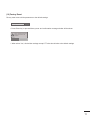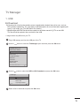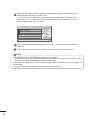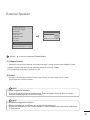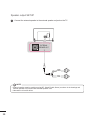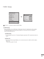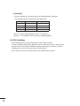
1
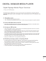
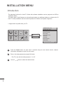
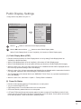
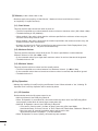
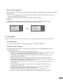
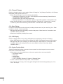
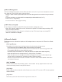
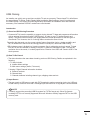
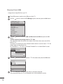
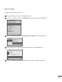
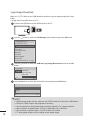
INSTALLATION MANUAL
LED TV*
* LG LED TV applies LCD screen with LED backlights.
Please read this manual carefully before operating
your set and retain it for future reference.
32LY340C-UA
42LY340C-UA
47LY340C-UA
55LY340C-UA
42LY540S-UA
47LY540S-UA
55LY540S-UA
32Y340H-UA
39Y340H-UA
42Y340H-UA
47Y340H-UA
55Y340H-UA
www.lg.com
TABLE OF CONTENTS
3
Digital Signage Media Player
3
Digital Signage Media Player Overview
4Installation menu
4
5
13
13
19
21
22
23
25
26
27
29
30
2
Introduction
Public Display Settings
TV Manager
-1. USB
-2. Diagnostics
Password Change
Set ID Setup
Configuration Setup
Multi Timer
Lock Mode
External Speaker
HCEC Setup
SuperSign Server Setup
Digital Signage Media Player
Digital Signage Media Player Overview
(* Only for LY540S series)
The Digital Signage Media Player can play content produced and distributed by SuperSign Elite-W.
Supported content types consist of photographs, videos, external inputs such as TV broadcasts, texts,
and music.
(1 ) Executable content
yy*.cts : These files can be played at any time.
yy*.sce : These files can be played at any time like *.cts files or they can be played to a specific schedule.
(2) Using the My Media menu to play files
yyAfter inserting the USB storage device, access the My Media menu and select an executable content
file under the “All Media” tab or the “Contents List” tab to play the file.
(3) Auto-play on USB insertion
yyFiles with executable content in a specific folder are automatically played when Power On is selected
or when a USB drive is inserted after Power On.
yyIf a USB storage device is already inserted when Power On is selected, files with executable content
in the “normal” folder are played by default. If the “normal” folder does not exist, files with executable
content in the “AutoPlay” folder are played instead.
yyIf a USB storage device is inserted some time after Power On has been selected, files with executable
content in the “AutoPlay” folder are played by default. If the “AutoPlay” folder does not exist, files with
executable content in the “normal” folder are played instead.
yyAuto-play on USB insertion is only supported by USB port #1.
(4) Distributing and playing content via SuperSign Elite-W
If a USB storage device is inserted in USB port #1, the LAN cable is connected and the SuperSign
yy
Server settings are configured, content can be received from the SuperSign Elite-W server.
yySchedules can be set to play a variety of specific content or media files, including photos and videos,
from SuperSign Elite-W whenever the user wants.
yyMessages created by the user can be sent to the player via SuperSign Elite-W.
yyFor more information, see the SuperSign Elite-W manual.
3
Installation Menu
Introduction
he abundant functions for Hotel TV linked with software installation can be projected on OSD as
T
‘Installation Menu’.
The wide range of hotel features can be performed simply on additional window to enhance the LG
hotel TV’s easy installation and convenient operation for Hotelier and System Integrators.
Image shown may differ from your TV.
yy
Installation Menu (V 3.0)
PICTURE
AUDIO
SETUP
TIME
7
TV
C05
LOCK
OPTION
INPUT
Smart Share
LG
Hotel
Mode Setup
Public
Display
Settings
TV Manager
Password Change
Set ID Setup
Configuration Setup
Multi Timer
Lock Mode
External Speaker
HCEC Setup
S/W : 02.00.00.01 Micom : 0.00.84
1
Press the Home button for more than 5 seconds using the user remote control, channel
information will appear at top left on the screen.
2
Enter a four digit password and press OK button.
• The TV is set with the initial password “1-1-0-5”.
3
4
OK
Use the
button to select the desired menu.
Public Display Settings
Image shown may differ from your TV.
yy
Installation Menu (V 3.0)
Public Display Settings (V 3.0)
▲
LG
Hotel
Mode Setup
Public
Display
Settings
TV Manager
Password Change
Set ID Setup
Configuration Setup
Multi Timer
Lock Mode
External Speaker
HCEC Setup
S/W : 02.00.00.01 Micom : 0.00.84
Public Display Mode
• Power On Status
• Volume
• Start Volume
• Maximum Volume
• Minimum Volume
• Key Operation
• IR Operation
▼
• Local Key Operation
OK
1
Use the
2
Use the OK button and then
Previous
◄
Yes
►
STD
No
Off
100
0
No
Normal
Normal
OK
button to select the Public Display Settings.
button to select Public Display Mode.
*When 'Public Display Mode' is set to Yes(Work), all functions of Public Display apply.
(1 ) Public Display Mode (ATSC)
Decide to work all functions of ‘Public Display Mode’ or not by setting 'Public Display Mode’ as
yy
Yes(Work) or No(Do Not Work)
When ‘Public Display Mode’ is set to Yes(Work), all functions of Public Display apply.
yy
When ‘Public Display Mode’ is set to No(Do Not Work), all functions of Public Display Do Not apply.
yy
When it is set to ‘Yes’, ‘Key Lock’ item of the User menu is disabled and the OSD is displayed same to
yy
the Local Key Operation setting of the Public Display.
When it is set to ‘Yes’, all items reserved at the Schedule list are deleted and the reservation function is
yy
not supported. (applied for the model offering the reservation function)
The TV triggered by the external device (ex: SIMPLINK, TVLink-Tuner, etc.) operates separately from
yy
the Public Display.
When it is set to ‘Yes’, User Menu-> Option -> ‘Factory Reset’ is disabled.
yy
(2) Power On Status
Decide to select working status of TV Set when turn on main power.
yy
You can set with PWR, STD, LST.
yy
PWR always make TV set On status when turn on main power .
yy
STD make Stand-by status when turn on main power.
yy
LST make TVSet work like previous power status. As same concept as Power Backup mode; If main
yy
power were turned off in Power On status, TVSet would work in On status. If main power were turned
off in Stand-by status, TVSet would work in Stand-by status.
5
(3) Volume (0 ≤ Min ≤ Start ≤ Max ≤ 100)
Decide to apply volume policy of ‘Start Volume’, ‘Maximum Volume’ and ‘Minimum Volume’
yy
as Yes(Work) or No(Do Not Work).
(3-1) Start Volume
This entry sets the start volume level when is power on.
The level is specified as a number between minimum volume to maximum value. (Min ≤ Start ≤ Max)
yy
The default setting is ‘Off’ (disabled).
yy
When enabled, if the value is lower then the minimum specified in the minimum volume entry, the
yy
minimum volume entry must be used.
When
enabled, if the value is larger then the maximum specified in the maximum volume entry, the
yy
maximum volume value must be used.
Access to a volume in ‘On Timer’ must be fixed to start volume when ‘Public Display Mode’ (Yes)
yy
and ‘Start Volume’ (Off, 0 ~ 100) were set simultaneously.
(3-2) Maximum Volume
This entry sets the maximum volume level the set. The level is specified as a number between
‘Minimum Volume’ to 100. (Min ≤ Max ≤ 100)
If the command volume up to higher than maximum volume’ is received, that should be ignored.
yy
The default value is 100.
yy
(3-3) Minimum Volume
This entry sets the minimum volume level the set will produce.
The level is specified as a number between 0 to ‘Maximum Volume’. (0 ≤ Min ≤ Max)
yy
If the command volume down to lower than minimum volume is received, that should be ignored.
yy
The default value is 0.
yy
(4) Key Operation
Manage key usability of Local(Front) Key and Remote Control. When selected to ‘Yes’, following ‘IR
yy
Operation’ and ‘Local Key Operation’ will be worked by below.
(4-1) IR Operation
Decide whether work the LG remote control or not.
Able to set Normal, Use PWR Only, Block All
yy
When ‘IR Operation’ is set to Block All, all normal remote keys don’t work. Use PWR Only (Block
yy
except power) makes block all remote keys except power key.
Although ‘IR Operation’ value is Use PWR Only or Block All.
yy
»»It can work in ‘Service mode’. (In-Start, In-Stop, Power-Only, ADJ, Hotel-Mode,
Hotel-Mode-Ready, P-Check, S-check, In-Time, FMode-Init, FMode-Start, FMode-AV, FMode-F1)
»»Menu key action to enter the ‘Installation Menu’ and key action with
‘Special menu(In-Start / EZ-Adjust …)’ are still available.
When ‘IR Operation’ is set to 0 (Work), all remote keys are available.
yy
6
(4-2) Local Key Operation
Decide to operate 'Local/Front Key' working behavior by setting ‘Local Key Operation’ as Normal, Use PWR
Only, Block All.
When 'Local Key Operation' is set to Block All, all local keys don’t work. If value is Use PWR Only, it
yy
blocks all local keys except power key.
When 'Local Key Operation' is set to Normal, all local key are available.
yy
Exception)
In case of power off condition with all key are blocked, ‘Power On Status’ value turns to ‘PWR’,
and disabled status to fix value for power on operation. (fool-proof routine)
• Power On Status
• Key Operation
• IR Operation
• Local Key Operation
◄
STD
►
◄
Yes
►
◄
Block All ►
◄
Block All ►
• Power On Status
• Key Operation
• IR Operation
• Local Key Operation
◄
PWR
►
◄
No
►
◄
Block All ►
◄
Block All ►
(5) Limited Mode
Configure TV function’s limitation. When selected to ‘Yes’, following sub-menus will be worked by below.
(5-1) Setup Menu
Decide to enter 'Setup’ Menu’ as ‘Yes’(Enter possible) or ‘No’(Enter impossible)
(5-2) Input Source Change
Decide to change input source or not by setting 'Input Source Change' as Yes(Change possible) or
No (Change impossible).
When ‘Input Source Change’ is set to ‘No’ (Change impossible)
yy
»»‘INPUT key’ doesn't work, and Input Source Changing via ‘TV D/A’ key, ‘TV/RADIO’ key aren’t possible (ex. Press TV/RADIO Key in HDMI source to view TV channel)
»»User's input (pressing Channel key, numeral key, List key, Q.View key in all Input source
except TV source) doesn't work.
»»Entering 'Setup Menu' item in the 'Main Menu OSD' except TV mode doesn't accepted.
Because entering 'Setup Menu' item makes present mode as TV mode even though present
mode is not TV. Change to TV mode isn’t allowed.
»»TV set always turns on fixed input source and volume information regardless of already
set information.
»»Entering 'Setup Menu' except TV mode is impossible regardless of ‘Channel Change'
or 'Setup Menu' items’ value.
»»TV can be only turned on with the input source which is irrelevant from the channel
related information set (volume, input) in ‘On Time’ Menu.
»»Auto AV and HDMI-CEC still work regardless of Input Source Change’s value.
»»When 'Input Source Change' is set to Yes(Change possible), changing input source is available.
7
(5-3) Channel Change
Decide to change channel or not by setting ‘Channel Change' as ‘Yes’(Change Possible) or ‘No’(Change
Impossible) when present source is TV.
When ‘Channel Change' is set to No (Change Impossible)
yy
»»Channel Key, Numeral Key, List Key, Q.View Key don't work and entering 'Channel Menu' in
the Main Menu OSD is impossible.
»»‘Channel' item in 'On Time' menu will be fixed.
»»Entering ‘Setup Menu' in the 'Main Menu’ OSD is impossible regardless of ‘Setup Menu' item.
When 'Channel Change’ is set to Yes(Change Possible), ‘Channel Key’, ‘Numeric Key’, ‘List Key’,
yy
‘Q.View’ Key does work and entering ‘Channel Menu' in the Main Menu OSD is possible.
(5-4) Menu Display
Function to decide whether work with menu (including relevant menus too) of control key (Yes – Enter
possible) or not (No – Enter Impossible).
Although select No(Enter impossible), the action that press a Menu button for 5 seconds to enter
yy
‘Installation Menu’ is available.
When select Yes(Enter possible), Menu works.
yy
(5-5) OSD Display
Decide to display OSD or not by setting ‘OSD Display’ as Yes(Display) or No(Do not Display).
When ‘OSD Display’ is set to ‘No’(Do not Display), all OSD is not displayed except some exception.
yy
Although select ‘No’ (Do not Display), the action that press a Menu button for 5 seconds to enter
yy
‘Installation Menu’ and entering service menu are available. (In-Start, Power-Only, Adjust,
Installation Menu …)
(5-6) System Provider Mode
‘System Provider Mode’ allows access to the menu system from the front panel or remote control
but access is controlled as follows:
When value is ‘Yes’, Accessible Items on the menu system, others are not permissible.
yy
»»Input select screens
»»Sleep timer
»»Aspect Ratio
»»Closed Caption
»»‘Lock’ / ‘My Media’ / ‘Network’ / ‘Support’ / ‘Bluetooth’ Menu
‘Q.menu’, which is related to ‘Setup’ Menu, is not accessible.
yy
If the channel map is empty, ‘Auto-tuning’ guide dialog should be blocked by pressing ‘List’, ‘Fav’,
yy
‘CH+’, ‘CH-’ keys.
8
(6) Power Management
The Power Management feature will turn off the television receiver if no input control command is received
from either the Local or IR Key within a selected hours.
Activity on either of these inputs shall restart the ‘Power Management’ timer and check key time interval
yy
again.
This entry can be set to a value which is corresponding to the desired hours (1 to 7).
yy
Default value is ‘Off(disabled)’.
yy
TV should off and on after apply this setting.
yy
(7) DTV Channel Update
It is a mode to set whether to update DTV channel information automatically or not.
When DTV Channel Update is set to ’Auto’, the function to update TV’s channel map according to DTV
yy
channel’s stream information
DTV Channel Update is set to ‘Manual’, the function to keep TV’s channel map even though DTV
yy
channel’s information is changed.
(8) Power On Default
Set the input source or channel to display and. A/V settings when turn on power in AC Power On or Standby status.
(8-1) Input Source
Set whether it is turned on by the set input source or by the last stored input source.
It is turned on by the Last Memory Input if the Input source is turned off.
yy
It is turned on by the Last Pr. If the Input source is turned off and the last memory Input is the RF.
yy
The available Input Source values should be rotated.
yy
If both the Input source and the ‘On Time’ menu are set, the Input source takes the priority.
yy
When the Input source is changed to the TV, Channel menu is available.
yy
When the Input source is changed to the ATV, the Program No. is set to 0. (If the channel map
yy
structure does not support this, it depends on model’s channel handling.
Access to an input source item and a channel in ‘On Timer’ menu must be disabled when Power
yy
On Default is activated.
(8-2) Tune Mode
Tune the selected start channel with physical or virtual method. Usually, digital channel uses virtual
channel and analog channel uses physical channel.
(8-3) Major
Select major part of start channel number if Input source value is TV. (in case of ATV, it means physical
channel number.)
(8-4) Minor
Select minor part of start channel number if Input source value is TV.
9
(8-5) A/V Setting
If ‘A/V Setting’ is changed from ‘No’ to ‘Yes’, parameters that are set before entering ‘Installation Menu’ are
applied whenever turn on power.
Following Parameters are applied to basic.
yy
»»Picture section - PSM mode, Picture Data (Contrast, Brightness, Color, Sharpness, Tint)
»»Sound section - SSM mode, Sound Data (Balance, Equalizer Data)
»»AVL (Auto Volume Level) and Language, Teletext language, ARC Data. Except these,
other parameters are applied differently according to the TV-Set.
(8-6) Aspect Ratio
The aspect ratio determines the default aspect ratio that the set returns to on power up.
The modes are as follows:
yy
»»Aspect ratio = “Disabled(0)” stays at previous state, same as consumer model.
»»Aspect ratio = “Set by Program(1)”
»»Aspect ratio = “4:3 ratio (2)”
»»Aspect ratio = “16:9 ratio (3)”
If enabled, upon power up the television reset the aspect ratio to the specified state regardless of
yy
how the user has previously changed the aspect ratio.
(9) Aux Source Setting
The Auxiliary (Input) Source Setting feature will enable or disable for each external input. When ‘Aux Source
Setting’ is set to Yes(Work), the RJP or HDMI-CEC / HTNG will not operate.
(9-1) Input Source
Available Input Source List
yy
(9-2) Setting
Decide whether selected ‘Input Source’ is usable (Enable) or not (Disable).
yy
User cannot disable the current input’s ‘Aux Source Setting’.
yy
10
(10) Factory Reset
Factory reset returns all the parameters to the default settings.
• Factory Reset
Confirm
Press ‘Enter key’ to proceed factory reset. and confirmation message window will be shown.
yy
All user settings and channel
settings will be reset. Still
Continue?
Yes
No
When select ‘Yes’, all television settings except UTT value should write to the default settings.
yy
11
Public Display Settings (Value Range Table)
Item
Public Display Mode
Power On Status
Volume
Start Volume
Enable
Disable
Yes
No
No
-
-
*STD
Yes
No
Off
Minimum Volume ~ 100
100
Minimum Volume
0 ~ Maximum Volume
Yes
0
No
No
IR Operation
Work (0) / Use PWR Only (1) / Bock All (2)
Work (0)
Local Key Operation
Work (0) / Use PWR Only (1) / Bock All (2)
Work (0)
Limited Mode
Yes
No
No
Setup Menu
Yes
No
Yes
Input Source Change
Yes
No
Yes
Channel Change
Yes
No
Yes
Menu Display
Yes
No
Yes
OSD Display
Yes
No
Yes
System Provider Mode
Yes
No
Power Management
Off, 1 ~ 7
DTV Channel Update
Auto
Power On Default
Yes
Input Source
Tune Mode
No
Off
Manual
No
Auto
No
Off, ATV, DTV, ...
Off
Physical / Virtual
Physical
Major
Subject to Ch. Type
2
Minor
Subject to Ch. Type
A/V Setting
Aspect Ratio
Aux Source Setting
Input Source
Settng
Factory Reset
12
No
Off, Minimum Volume ~ Maximum Volume
Maximum Volume
Key Management
Initail
Yes
0
No
Disable (0) / Set by Program (1) / 4:3 (2) / 16:9 (3)
Yes
No
Aux Input(AV1 ~ MAX_INPUT)
Enable
Disable
Confirmation window (Yes / No)
No
Disable
No
AV1
Enable
TV Manager
1. USB
Ez Download
Ez Download is a function that enables users to download the desired items all at once, such as
EPK (software update file), TLL (see Send to USB descriptions for more information regarding file
types), Logo Image, etc (TLX, MICOM for Pro:Centric).
* Splash images and EPK files should be copied into the folder named LG_DTV on the USB.
TLL files should be copied to the root folder of the USB.
Image shown may differ from your TV.
yy
1
Plug USB memory card into the USB port of the TV.
2
Use the
button to select the TV Manager option and then press the OK button.
Installation Menu (V 3.0)
Public Display Settings
TV Manager
Password Change
Set ID Setup
Configuration Setup
Multi Timer
Lock Mode
External Speaker
HCEC Setup
S/W : 02.00.00.01 Micom : 0.00.84
3
OK
button to select the USB and Ez Download and press the OK button.
Use the
TV Manager
USB
Diagnostics
Ez Download
Receive from USB
Send to USB
Logo Image Download
Previous
4
OK
Select a list to download and press the OK button.
13
5
Select the EPK option (software update) and then use the green and yellow buttons to
download either SPI Boot or LG Boot Logo.
If you checked the LG Boot Logo checkbox, then the Splash image, if selected, will be
unchecked. Also, if you select the LG Boot Logo and proceed with the download, the
existing Splash image will be deleted.
Ez Download
[TLL] GlobalClone00001.TLL
[LOGO] 1360X768.jpg
[EPK] M1A_DVB_CN_RevNo1901_V02.0...
[ TV Software Version ]
Current : 02.00.00.01
EPK : 02.00.00.01
[ Forced Update Option ]
SPI Boot
LG Boot Logo
Apply
Previous
OK
6
When you are finished with your selections, use the (->) button to select Apply and then
press OK.
7
Wait for the download to complete. When it is finished, your TV will be turned off.
NOTE
y If the DZM file is still in the USB after the download is complete:
- An Ez Download pop-up window will appear and list the file types, such as TLL, LOGO, or EPK,
with the previously downloaded lists checked automatically.
y If the global TLL and model TLL files exist in the same USB root directory, then only the global TLL
will be shown.
If the global TLL has been deleted, then the model TLL will be shown.
14
USB Cloning
An Installer can quickly set up and clone multiple TV sets at a property. These cloned TVs will all have
the same Master TV Setup: Public Display Mode Installation Menu settings, User A/V settings and
the Channel Map. This newer procedure significantly decreases the installation time that would be
necessary if the standard RS-232C method were used instead.
Introduction
(1) Overview USB Cloning Procedure
Commercial TVs have the capability to support cloning internal TV data and programme information
yy
with an external clone device called “USB Cloning”, in order to copy TV data accurately and
quickly. The clone internal functions use slightly different internal processes for the two types of
commercial TVs. However, the UI of cloning feature remains the same in both.
Regarding the demands over the current cloning feature for quicker clonin g, better portability and
etc, we would like to announce the cloning process via USB port, named as USB Cloning.
USB cloning process is divided into 2 main processes. One is writing the previously saved TV data
into the TV, and one another is reading of current TV data into USB memory card. To avoid any
confusion due to the words, it is clearly specified as “Receive from USB” and “Send to USB” in the
whole process.
(2) Data To Be Cloned
The data cloned are the same data cloned by previous USB Cloning. Details are explained in the
yy
following:
1. TV data includes:
A. Installer Menu settings
B. Main menu settings (Audio, Picture etc)
2. Analog / Digital Channel information includes:
A. Channel numbers
B. Channel label
C. Channel attributes including channel type, skipping status and etc.
(3) Input Source
The user needs a USB memory card with FAT formatted to make successive cloning via USB port.
yy
A USB memory card size more than 128 Mega Bytes and less than 4 Giga Bytes is recommended.
NOTE
Currently, support the preceding USB file system for FAT file format only. Other file formats
yy
including NTFS is not currently supported. Microsoft Windows officially supports FAT for the USB
memory card.
15
Receive From USB
Image shown may differ from your TV.
yy
1
Plug USB memory card into the USB port of the TV.
2
Use the
button to select the TV Manager option and then press the OK button.
Installation Menu (V 3.0)
Public Display Settings
TV Manager
Password Change
Set ID Setup
Configuration Setup
Multi Timer
Lock Mode
External Speaker
HCEC Setup
S/W : 02.00.00.01 Micom : 0.00.84
3
OK
Use the
button to select the USB and Receive from USB and press the OK
button.
* Below explains the naming rules for .TTL files.
The supported model line will be in the name of the file but the screen size will be
listed as “xx”.
This allows TVs having the same chassis model number to use the same ‘*.TTL’ file
without regard to the screen size.
ex) The name of ‘*.TTL’ file is ‘xxLP360H-TA00000.TLL’ for 32/42LP360C model.
TV Manager
USB
Diagnostics
Ez Download
Receive from USB
Send to USB
Logo Image Download
Previous
4
Use the
OK
button to select the desired *.TTL files name and press the OK button.
Receive from USB (USB Port1)
Select file type
Global TLL
Model TLL
GlobalClone00001.TLL
Previous
5
16
OK
The TV is changed to Standby mode after a successful download.
If the download failed, the TV will changed to the initial installation screen.
Send To USB
Image shown may differ from your TV.
yy
1
Plug USB memory card into the USB port of the TV.
2
Use the
button to select the TV Manager option and then press the OK button.
Installation Menu (V 3.0)
Public Display Settings
TV Manager
Password Change
Set ID Setup
Configuration Setup
Multi Timer
Lock Mode
External Speaker
HCEC Setup
S/W : 02.00.00.01 Micom : 0.00.84
3
OK
button to select the USB and Send to USB and press the OK button.
Use the
TV Manager
USB
Diagnostics
Ez Download
Receive from USB
Send to USB
Logo Image Download
Previous
4
Use the
OK
button to select the desired file name and press the OK button.
Send To USB (USB Port1)
Select file type
Global TLL
Model TLL
Select the file name and press OK to start
▲
GlobalClone00001.TLL
▲
Previous
5
OK
The TV is changed to the initial installation screen after a successful download.
17
Logo Image Download
1
2
AKER
UT
RGB IN (PC)
1
AV
(RGB)
IN 3
AUDIO IN
ONENT
OPTICAL
(COMPONENT/RGB/DVI) AUDIO OUT
N
Connect the USB device to the USB IN jack on the TV.
USB IN
/DVI IN
PCMCIA CARD SLOT
Make a ‘LG_DTV’ folder on the USB flash drive and then copy the splash image file to that
folder.
Image shown may differ from your TV.
yy
RS-232C IN
(CONTROL & SERVICE)
ANTENNA/
CABLE
IN
button
Use the
to select the TV Manager option and then press the OK button.
Installation Menu (V 3.0)
LG Hotel Mode Setup
H/P OUT
2
TV Manager
Password Change
Set ID Setup
Configuration Setup
Multi Timer
Lock Mode
External Speaker
HCEC Setup
S/W : 02.00.00.01 Micom : 0.00.84
3
OK
button to select the USB and Logo Image Download and press the OK
Use the
button.
TV Manager
USB
Diagnostics
Ez Download
Receive from USB
Send to USB
Logo Image Download
Previous
4
Use the
OK
button to select the desired file name and press the OK button.
Logo Image Download
Image1.jpg
Image2.jpg
Image3.jpg
Previous
OK
NOTE
18
► Splash Image update function supports only JPEG format file of less than 1 MB filesize..
► Except for JPEG images with progressive encoding.
► We recommend you that splash image resolution match the TV`s panel resolution.
► 'Max resolution of splash image : Full HD->1920x1080, HD->1360x768.
► 'Min resolution of splash image : Full HD->64x64, HD->64x64.
► TV keep splash image until you change a new splash image.
2. Diagnostics
Diagnostics Setup
Introduction
This diagnostic function provides current status information of the TV in XML file format using a USB
device. If the user sets a signal standard level, SignalTrace checks the signal strength status of the
digital channel that the user tuned to. It checks and records good and bad channel signals, and then
provides the signal information to a USB storage device in XML file format.
Installation Menu (V 3.0)
TV Manager
Public Display Settings
TV Manager
Password Change
Set ID Setup
Configuration Setup
Multi Timer
Lock Mode
External Speaker
HCEC Setup
S/W : 02.00.00.01 Micom : 0.00.84
USB
Diagnostics Setup
Diagnostics
Previous
OK
OK
(1) Overview Diagnostics
1 It provides status information of the TV and information about the current input in XML file format.
(There are two kinds of information. There is information which is extracted regardless of the model,
such as the model name or boot version, and there is information which is available depending on
the model, such as the micom version, PTC version, etc.). The information created in the XML file
can be checked in the TV's UI by pressing 88888888 in the TV's Option menu.
2 If a SignalTrace standard level is set, it saves the average value of the channel signal with less than
30 tuning counts to the digital broadcasting channel. If the count is more than 30, it saves good and
bad signals by comparing the average signal value to the current signal strength and signalTrace
standard level (SignalTracer Set) value.
▷ Bad signal: BML (average value) > strength (current signal strength) and (BML - strength) >
SignalTracer Set
▷ Good signal: BML< strength and (strength - BML) > SignalTracer Set
It provides the good and bad signals, average signal value, channel information, and date information
etc. in USB in XML file format. (Saved in changedSignal_report tag) Up to 127 reports for good and
bad signals are saved. If the reports number more than 127, they are written again beginning from 1.
(2) Saving some status information of the TV set through USB in XML file format
Create an LG_SVC folder on the USB on a PC.
yy
Create an empty file named tv_signal.rms in the LG_SVC folder.
yy
Insert the USB device into the TV.
yy
If the "Diagnostics is completed" message is displayed, remove the USB, open the tv_signal.rms file on a PC and
yy
check the XML (model name, FirmwareVersion, bootVersion etc.) created within the file.
The information created in the XML file can be checked in the TV's UI by pressing 88888888 in the TV's Option
yy
menu.
19
(3) Saving signal status information of digital channels through SignalTrace in XML format
Go to Installation menu -> TV Manager -> Diagnostics -> Diagnostics Setup
yy
Set the level value in Signal Tracer Set. (Disable, 10 to 90)
yy
TV Manager
USB
Diagnostics Setup
Diagnostics Setup
Signal Tracer Set
Diagnostics
Previous
Previous
◄
Disable
►
OK
OK
Change the channel and tune to a digital channel, then maintain the status for more than 5
yy
seconds.
Create an empty file named tv_signal.rms in the LG_SVC folder.
yy
Insert the USB device into the TV.
yy
If the "Diagnostics is completed" message is displayed, remove the USB, open the tv_signal.rms
yy
file on a PC and check XML created in the file.
※ If the user tunes to the same digital channel 30 times, the signal average is calculated. If the tuning
count to the same digital channel is more than 30, the good/bad signals, current signal, average signal,
date and channel information are saved in changedSignal_report XML tag.
※ The information created in SignalTrace is not displayed in the TV's UI.
※ In USB cloning, the configured Signal Tracer value is not cloned.
※ When a factory reset is performed, Signal Tracer Set is disabled and traced information is deleted.
20
Password Change
Image shown may differ from your TV.
yy
-To ensure more security, Password can be changed by installers’ own design.
Installation Menu (V 3.0)
Public Display Settings
TV Manager
Password
PasswordChange
Change
Set ID Setup
Configuration Setup
Multi Timer
Lock Mode
External Speaker
HCEC Setup
S/W : 02.00.00.01 Micom : 0.00.84
Password Change
Change Password
*
*
*
Confirm Password
*
*
*
Previous
*
*
OK
OK
1
Use the
2
Enter four digit password.
3
Input the password again for confirmation.
button to select the Password Change and then press the OK button.
21
Set ID Setup
Installation Menu (V 3.0)
Public Display Settings
TV Manager
Password Change
Set
Set ID
ID Setup
setup
Configuration Setup
Multi Timer
Lock Mode
External Speaker
HCEC Setup
S/W : 02.00.00.01 Micom : 0.00.84
1
Use the
Set ID Setup
Set ID Lock
Set ID
Previous
◄
Yes ►
1
OKOK
OK
button to select the Set ID Setup.
• Set ID Lock
- Set the ‘Set ID’ item in ‘Option’ Menu whether to activate or not.
- Set to Yes(Work) or No(Do Not Work).
• Set ID
- Set the ‘Set ID’ of TV Set with 1~99.
22
Configuration Setup
Image shown may differ from your TV.
yy
Configuration Setup
Installation Menu (V 3.0)
Number of RCU
Public Display Settings
TV Manager
Password Change
Set ID Setup
Configuration
ConfigurationSetup
Setup
Multi Timer
Lock Mode
External Speaker
HCEC Setup
S/W : 02.00.00.01 Micom : 0.00.84
Splash Offset Time
Big UI Display
USB Auto Playback
15Min Auto Off
Auto Sensing
OK
0
+0 Sec
◄
No ►
Disable
Enable
To Set
Forced DVI Audio
Off
Screen Saver Cube
Yes
Video Mute
No
Noise Mute
No
Previous
OK
(1) Number of RCU
It is a function to set whether to use Select RCU or not and set number of RCU.
yy
When Number of RCU is set to ‘0’, this function do not use.
yy
yyNumber of RCU value range 1~9
* RCU(Remote Control Unit) : It is special RCU that operates only setted number of RCU in TV.
yy
(2) Splash Offset Time
Set the splash image display time
yy
When Splash Offset Time is set to ‘OFF’, TV logo(splash image) do not display.
yy
The time can be set to between 0 and 10 seconds.
yy
(3) Big UI Display
When ‘Big UI Display’ is set to ‘Yes’, TV displays enlarged Channel Banner UI.
yy
(4) USB Auto Playback
When ‘USB Auto Playback’ is set to ‘Movie’, TV finds and plays the USB’s movie files located at
yy
the root(top) directory Movies if USB is plugged in. (Some menu OSDs may prevent this function.)
When ‘USB Auto Playback’ is set to ‘Photo’, TV finds and plays the USB’s photo files located at the
yy
root(top) directory Photos if USB is plugged in. (Some menu OSDs may prevent this function.)
If it reaches the last file, it starts the first file again.
yy
23
(5) 15Min Auto Off
When ‘15Min Auto Off’ is set to ‘Enable’, TV will turn off if there is no signal in 15Min.
yy
(6) Auto Sensing
-If 'Auto Sensing' is set to 'To Set ⊙', the input is automatically switched when the input signal that
yy
you set to 'ON' is received.
If SIMPLINK is set to On, HDMI is automatically set to Disable and can not work.
yy
If the signal is removed while Auto Sensing (automatic input switch) is enabled, the input returns to
yy
the previous setting.
If the several inputs are connected by enabling Auto Sensing and the automatic input switch is
yy
performed several times, the input returns to the previous setting only for the last input and does
not repeat the operation for the rest.
For the AV input connected using the euro scart cable, Auto Sensing does not work for the TV
yy
input because the Auto AV function is enabled.(For other inputs, Auto Sensing works normally.)
(7) Forced DVI Audio
When Forced DVI Audio is selected, the audio signal from the HDMI port will be transmitted
yy
through the RGB, AV, or Audio In #1 component ports.
The video signal will be transmitted through HDMI to be displayed on the screen in standard
yy
quality.
For the audio signal, the priority order is the RGB -> AV -> Audio In component ports.
yy
(8) Screen Saver Cube
When ‘Screen Saver Cube’ is set to ‘No’, TV will do not display LG Screen Cube.
yy
(9) Video Mute
When 'Video Mute' is set to 'Yes', for Blank.
yy
(10) Noise Mute
When 'Noise Mute' is set to 'Yes', audio mutes when no signal is present.
yy
24
Multi Timer
Installation Menu (V 3.0)
Public Display Settings
TV Manager
Password Change
Set ID Setup
Configuration Setup
Multi
MultiTimer
Timer
Lock Mode
External Speaker
HCEC Setup
S/W : 02.00.00.01 Micom : 0.00.84
1
Use the
Multi Timer
Multi Timer
◄
On
►
On Timer
Off Timer
Previous
OK
OK
button to select the Multi Timer.
(1) Multi Timer
It is a mode to set whether to use or not.
yy
When ‘Multi Timer’ is set to ‘On’, You can adjust ‘On Timer’, ‘Off Timer’ menu.
yy
(2) On Timer
It sets the time for turning the TV on. A maximum of 5 timers can be set.
yy
(3) Off Timer
It sets the time for turning the TV off. A maximum of 5 timers can be set.
yy
25
Lock Mode
Installation Menu (V 3.0)
Public Display Settings
TV Manager
Password Change
Set ID Setup
Configuration Setup
Multi Timer
Lock
LockMode
Mode
External Speaker
HCEC Setup
S/W : 02.00.00.01 Micom : 0.00.84
1
Use the
Lock Mode
Data Service
◄
Enable ►
USB
Enable
Factory Reset
Enable
Previous
OK
OK
button to select the Lock Mode.
- If 'Lock Mode' items are disabled, the following features will be unavailable.
Data Service(Teletext, EPG, Sub-Title, Caption (Include MPEG4), MHEG)
yy
USB Enable(Exclude S/W update)
yy
Factory Reset
yy
26
External Speaker
Installation Menu (V 3.0)
Public Display Settings
TV Manager
Password Change
Set ID Setup
Configuration Setup
Multi Timer
Lock Mode
External
ExternalSpeaker
Speaker
HCEC Setup
S/W : 02.00.00.01 Micom : 0.00.84
1
Use the
External Speaker
Volume Control
Output
Previous
◄
Fixed ►
1 Watt
OK
OK
button to select the External Speaker.
(1) Volume Control
Selects the volume control method of an external speaker. You can choose either Variable or Fixed.
yy
Variable is linked to the main volume OSD and change the volume 0-1 Watts.
Fixed produces a fixed output. The default is Off.
(2) Output
This item is enabled when Volume Control is set to Fixed. You can choose one of 7 steps.
yy
(0.01/0.03/0.05/0.1/0.2/0.5/1 Watts)
NOTE
(Optical supported models)
If You use External Speaker as Variable Mode, External Speaker will be off when you select
yy
'External Speaker(Optical)' in Sound-Out menu.
NOTE
(HeadPhone supported models)
External Speaker and HeadPhone can not be used simultaneously.
yy
Disconnect Headphone to use External Speaker. External Speaker only works when HeadPhone
yy
is disconnected.
27
Speaker output SETUP
1
Connect the external speaker to the external speaker out jack on the TV.
EXTERNAL
SPEAKER OUT
GND
RIGHT
LEFT
GND
NOTE
External speaker must be used three plug(SE : Single Ended, Stereo) as shown in the drawings and
yy
external speaker fully inserted with external Speaker Jack.
Otherwise it will cause defect.
yy
28
HCEC Setup
Installation Menu (V 3.0)
Public Display Settings
TV Manager
Password Change
Set ID Setup
Configuration Setup
Multi Timer
Lock Mode
External Speaker
HCEC
HCEC Setup
Setup
S/W : 02.00.00.01 Micom : 0.00.84
1
Use the
HCEC Setup
CEC Mode
◄
Default ►
IR Decoding
No
Device ID
All
StandBy
All
HTNG HotelMode
Previous
No
OK
OK
button to select the HCEC Setup.
(1) HCEC Setup
When CEC Mode is set to 'HCEC Mode', 'IR Decoding', 'Device ID', 'Stand By' item will be enabled,
yy
and SIMPLINK feature will be automatically changed to ‘On’ state and user will not change this
status through SIMPLINK menu.
(a) IR Decoding
If 'IR Decoding' is set as 'Yes', TV decodes IR signal to generate a CEC command and sends it to
yy
device.
(b) Device ID
Sets the ID of Device(Logical Address). You can choose from 0x01 to 0x0E and 'All' the default
yy
value is 'All'.
* This works only when TV is ON.
29
(c) Stand By
Sets the sending and receiving scenario of OpStandBy(0x0c) command.
yy
The detailed scenario is described on the table below.
yy
Send
Receive
Send Only
O
X
Receive Only
X
O
All
O
O
OFF
X
X
* Send : TV sends OpStandBy(0x0c) when TV is turned off.
* Receive : TV is available to be turned off by OpStandBy(0x0c)
(2) HTNG HotelMode
If the following options are selected because of the HTNG command:
yy
*Power On Default, Start Volume, Maximum Volume, Minimum Volume, or Start Volume,
then the value for the HTNG HotelMode changes automatically to Yes and, even if the
HotelMode is set to No, the above options are still affected.
If you change it to No, then the values set by the HTNG will be canceled.
yy
30
SuperSign Server Setup
(* Only for LY540S series)
Installation Menu (V 3.0)
Public Display Settings
TV Manager
Password Change
Set ID Setup
Configuration Setup
Multi Timer
Lock Mode
External Speaker
HCEC Setup
SuperSign Server Setup
Play Name
Press OK
Server IP Setting
Press OK
Server IP Status
Not connected
Previous
OK
SuperSign Server Setup
S/W : 02.00.00.01 Micom : 0.00.84
1
Use the
OK
button to select the SuperSign Server Setup.
(1) Play Name
You can set the name of a player you want to control in SuperSign Manager. (Up to 20 characters.)
yy
(2) Server IP Setting
You can set the IP address of the computer (server) on which SuperSign Manager is installed.
yy
(3) Server IP Status
It displays the connection status with the server.
yy
- Not connected: Your TV is not connected to the SuperSign server.
- Waiting for Approval: Your TV is connected to the SuperSign server but not yet approved.
- Rejected: Your TV is connected to the SuperSign server but has been rejected.
- Connected: Your TV is connected to the SuperSign server and has been approved.
31
32