1
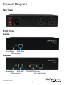
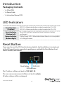
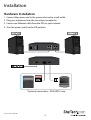
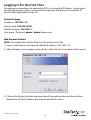
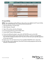
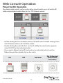
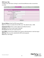
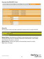
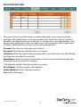
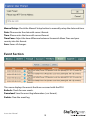
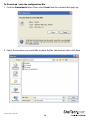
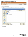
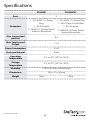
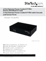
2 Port Remote Power Control IP PDU
(Power Distribution Unit)
2 Port Remote Power Control IP PDU with Console
and Sensor Ports
PDU02IP / PDU02IPSC
*PDU02IP shown in photo
DE: Bedienungsanleitung - de.startech.com
FR: Guide de l'utilisateur - fr.startech.com
ES: Guía del usuario - es.startech.com
IT: Guida per l'uso - it.startech.com
NL: Gebruiksaanwijzing - nl.startech.com
PT: Guia do usuário - pt.startech.com
For the most up-to-date information, please visit: www.startech.com
Manual Revision: 01/02/2014
FCC Compliance Statement
This equipment has been tested and found to comply with the limits for a Class B digital
device, pursuant to part 15 of the FCC Rules. These limits are designed to provide reasonable
protection against harmful interference in a residential installation. This equipment generates,
uses and can radiate radio frequency energy and, if not installed and used in accordance with
the instructions, may cause harmful interference to radio communications. However, there
is no guarantee that interference will not occur in a particular installation. If this equipment
does cause harmful interference to radio or television reception, which can be determined by
turning the equipment off and on, the user is encouraged to try to correct the interference by
one or more of the following measures:
• Reorient or relocate the receiving antenna.
• Increase the separation between the equipment and receiver.
• Connect the equipment into an outlet on a circuit different from that to which the receiver
is connected.
• Consult the dealer or an experienced radio/TV technician for help.
Use of Trademarks, Registered Trademarks, and other Protected Names and Symbols
This manual may make reference to trademarks, registered trademarks, and other
protected names and/or symbols of third-party companies not related in any way to
StarTech.com. Where they occur these references are for illustrative purposes only and do not
represent an endorsement of a product or service by StarTech.com, or an endorsement of the
product(s) to which this manual applies by the third-party company in question. Regardless
of any direct acknowledgement elsewhere in the body of this document, StarTech.com hereby
acknowledges that all trademarks, registered trademarks, service marks, and other protected
names and/or symbols contained in this manual and related documents are the property of
their respective holders.
Instruction Manual
Table of Contents
Product Diagram.....................................................................................1
Rear View....................................................................................................................................................... 1
Front View..................................................................................................................................................... 1
Introduction.............................................................................................2
Packaging Contents.................................................................................................................................. 2
LED Indicators..........................................................................................2
Reset Button............................................................................................2
Installation ..............................................................................................3
Hardware Installation............................................................................................................................... 3
Logging In for the First Time.................................................................................................................. 4
Web Console Operation.........................................................................6
Power Switch Operation.......................................................................................................................... 6
Monitor Section.......................................................................................................................................... 7
UPS Status (PDU02IPSC Only)................................................................................................................ 9
Dry Contact Input Indication (PDU02IPSC Only)............................................................................ 10
System Section............................................................................................................................................ 10
Firewall Section........................................................................................................................................... 15
Account Section......................................................................................................................................... 17
TimeSync Section....................................................................................................................................... 18
Event Section............................................................................................................................................... 19
Instruction Manual
i
Firmware Upgrade Procedure...............................................................22
Specifications...........................................................................................23
Technical Support...................................................................................24
Warranty Information.............................................................................24
Instruction Manual
ii
Product Diagram
Rear View
Front View
PDU02IP
Reset Button
RJ45 LAN
LED Indicators
PDU02IPSC
Reset Button
RJ45 LAN
RS232 UPS Console
LED Indicators
Instruction Manual
Dry Contact Input
1
Introduction
Packaging Contents
• 1 x 2 Port PDU
• 1 x Power Cable
• 1 x Instruction Manual (CD)
LED Indicators
Port Indicators
(Top Row)
LED #1 is illuminated when output receptacle #1 is ON.
Reset Indicator
(Bottom Left)
Reset LED will flash when the Reset function is being
performed.
Power Indicator
(Bottom Right)
Utility Power LED is illuminated when there is an acceptable
AC voltage Present.
LED #2 is illuminated when output receptacle #2 is ON.
Reset Button
If you need to reset the PDU back to factory defaults, the Reset Button is located next
to the LED panel. Insert a paperclip to gently press and hold the Reset Button for at
least 3 seconds, then release.
Reset Button
RJ45 LAN
LED Indicators
The IP address will be reset back to 192.168.1.10
The user name and password will be reset back to admin.
All other settings will be unchanged.
Instruction Manual
2
Installation
Hardware Installation
1. Connect the power cord to the power inlet and to a wall outlet
2. Plug your equipment into the two output receptacles
3. Connect an Ethernet cable from the PDU to your network
4. Turn the power switch to the ON position
*Optional connections - PDU02IPSC only
Instruction Manual
3
Logging In for the First Time
The minimum requirement to operate the PDU is to setup the IP Address, subnet mask,
and default gateway, which can be done through your web browser or using the IP
Search Utility application on the CD.
Default Settings:
IP address: 192.168.1.10
Subnet mask: 255.255.255.0
Default Gateway: 192.168.1.1
User name / Password: admin / admin (lower case)
Web Browser Method
NOTE: The workstation and the PDU must be on the same LAN
1. Open a web browser and input the default IP address (192.168.1.10)
2. After the login screen appears enter admin / admin for the User name and Password
3. Click on the System tab from the menu bar of the web interface and then click on
Network to set the IP address and network info of this device
Instruction Manual
4
IP Search Utility
NOTE: The workstation and the PDU must be on the same LAN for the IP Search Utility
to detect it, and the Windows Firewall must also be turned off.
1. Open the Windows Control Panel
2. Select Windows Firewall
3. Select Off and then click the OK button
4. Insert the provided CD in the CD-ROM drive
5. Launch the IP Search Utility program
6. Click on the Refresh button to search for all PDU02IPxx units on the LAN
7. Click on the detected PDU and configure the IP address, Gateway and Net Mask,
then click the Configure button twice. You will see the values you specified populate
in the main window
8. Repeat step 7 for each device if you have multiple PDU02IPxx units connected
9. Once all devices are configured, close the IP Search Utility program and turn the
Windows Firewall back on
Instruction Manual
5
Web Console Operation
Power Switch Operation
The global outlet controls can be used to either turn all outlets on, or all outlets off,
while each individual outlet allows for On / Off / Reboot controls.
• Double clicking the ALL ON button will turn ON both outlets. Double clicking on the
ALL OFF button will turn OFF all of the outlets.
• Double clicking the switch for Port 1 or Port 2 will flip the switch to the opposite
state (ON/OFF) for that individual outlet.
• If you want to Reboot (cycle off, then back on) an individual outlet, check the
Reboot box and then double click on the switch.
ON
Instruction Manual
OFF
No Power
6
Not Authorized
(User account
restruction)
Monitor Section
The Monitor section shows you the current status of each outlet and allows you to
modify the power state of each outlet individually, or make global changes to both.
From the Monitor tab you can also Schedule events and configure the
Auto-Ping feature.
Configuration Tab
Click on the Set button located on the top corner of each outlet to modify an
individual outlet. When the Set button is orange, the outlet is ready to be configured.
Description: Allows you to give each outlet a more meaningful name if desired
Start Delay Time: Each outlet can be programmed to startup at different time
intervals instead of both of them starting up at the same time.
Shutdown Delay Time: Each outlet can be programmed to shutdown at different
time intervals instead of shutting both of them down at the same time.
Save: Saves all changes.
Instruction Manual
7
Schedule Tab
Configure scheduled actions for each outlet. Click on the Set button located on the top
corner of each outlet to modify an individual outlet. When the Set button is orange, the
outlet is ready to be configured.
Recurrence: An Action can be scheduled to occur yearly, monthly, weekly or daily at
a specific time for each individual outlet.
Time: Set the time (hours and minutes) when you want the action to occur.
Action: Set the action you want the outlet to perform, ON, OFF or Reboot.
ADD: Click the ADD button to add this action.
Delete: To delete a scheduled action, double-click on the “X”.
Save: Saves all changes.
Network Tab
Configure the Auto-PING feature to ping an IP-addressable device and detect when
that device has stopped communicating. Click on the Set button located on the top
corner of each outlet to modify an individual outlet. When the Set button is orange,
the outlet is ready to be configured.
Detect: Check this box to enable the Auto-Ping function.
Equipment Network Address: Enter the IP address of the connected equipment.
PING Interval Time: Set the time Interval to PING the connected device.
Detect Times: If a device fails to respond to a ping continuously and exceeds the
specified amount of attempts, the PDU02IPxx can notify selected personnel via email
or SMS.
Reboot: Check this box to reboot the outlet for the failed connected device.
Re-detect Time: The time interval before restarting the Auto-Ping function after the
connected device has been rebooted.
Save: Saves all changes.
Instruction Manual
8
UPS Status (PDU02IPSC Only)
The UPS Status information will display to the left of the power switches on the
Monitor Tab. If you have connected an APC Smart UPS series device to the RS232 port
on the PDU02IPSC, you can monitor the following information about your UPS.
Alive - Displays the state of the UPS device as either Normal (1) or Offline (0).
Model - Displays the connected UPS model.
AC Fault - Displays if there is an AC fault causing the equipment to function on UPS
battery power – Normal (0), AC Fault (1)
Output Overload - Displays either Normal (0) or Overload (1) state - Overload is
shown if the power draw exceeds the output limit set by the UPS when operating on
battery power.
Battery Level(%) - Displays the remaining battery capacity as a percent value.
Battery Run Time (Min) - Displays the remaining battery capacity in minutes.
Battery Low - Displays either Normal (0) or Low (1) state – the Low state threshold is
set by the UPS.
Replace Battery - Displays either Normal (0) or Needs Replacement (1) - the Needs
Replacement state threshold is set by the UPS.
Instruction Manual
9
Dry Contact Input Indication (PDU02IPSC Only)
The dry contact status information will display to the right of the power switches on
the Monitor Tab. If you have connected and configured the Detectors information
(located in System > Detectors section – explained in the following pages), you will see
a Normal or Abnormal indication.
Status Illustration:
Normal Abnormal
System Section
Network Tab
Configure the PDU with a Static IP address or use DHCP.
Instruction Manual
10
Http Port: Assign the desired HTTP port (default is port 80) for connecting to the PDU
via a web browser. If you change the HTTP port, enter the IP address followed by the
new HTTP port into your browser address bar (e.g. http://192.168.1.10:8080).
Save: Saves all changes.
Mail Server Tab
Configure the Mail Server settings to send notifications when an event has occurred.
SMTP Server Address: Enter the Hostname or IP address of the SMTP Mail Server that
will be used to send emails from the PDU. If entering a Hostname, you will also be
required to enter the DNS Address on the Network tab.
SMTP Port: Enter the port number for the SMTP server. The default port is 25.
Sender Mail Address: This must be a legitimate email address.
Mail Subject: Enter a subject line to easily identify the device.
SMTP Auth: Check this box if the Mail Server requires authentication to send emails.
SMTP Account: Enter the account name if SMTP authentication is required.
SMTP Password: Enter the password if SMTP authentication is required.
Mail Test: This is used to verify that the email works properly.
Save: Saves all changes.
Instruction Manual
11
SMS Server Tab
Configure the SMS Server settings to send text notifications when an event has
occurred.
Server Address: Enter the SMS server address.
Port: Enter the port number for the SMS server. The default value is 2500.
Equipment Name: Enter a name/subject to identify the device.
Account: Enter the account name if required.
Password: Enter the password if required.
Send SMS: Check this box if SMS Server requires authentication to send messages.
SMS Test: This is used to verify that the SMS works properly.
Save: Saves all changes.
Instruction Manual
12
SNMP/SysLog Tab
Configure SNMP Traps and System Logs to be sent to different Network Management
Stations (NMS).
System Name: Enter the name of the SNMP device.
System Contact: Enter the name of the System Administrator.
System Location: Enter the location of the SNMP device.
Receiver IP Address: The IP Address of the NMS of where the Traps should be sent.
Receiver Port: The port that will be used to receive the Traps. The default value is 162.
Community: Low-level password of the associated IP address with the access type set
by the administrator.
Enabled: Enables the SNMP Traps to be sent.
SNMP Test: This is used to verify that the Trap notification works properly.
Syslog Server Address: The IP Address of the Server to which the System Logs should
be sent.
Syslog Server Port: The port that will be used to receive the System Logs.
Save: Saves all changes.
Instruction Manual
13
Detectors Tab (PDU02IPSC Only)
Other Tab
Set the outlets on the main tab to default to a reboot action, instead of ON/OFF.
Reboot Option: Check this box to default to rebooting the outlet instead of just
turning the outlet ON/OFF. The Reboot check box on the Monitor screen will be
checked when this option is selected.
Reboot Device: Selecting this option will immediately reboot the outlets.
Save: Saves all changes.
Instruction Manual
14
Firewall Section
This menu allows the administrator to configure user privileges and prevent
unauthorized access to the device.
IP Filter Tab
Configure the range of IP addresses that are able to access the PDU.
IP Filter Enable: Check this box to enable the IP address filter.
Allow IP Address: The first four sections are the beginning of the IP range. The last
section is the ending of the IP range that is being given access to the device.
E.g. To authorize the IP range from 192.168.1.110 - 192.168.1.120, input as shown in the
image above
ADD: Click ADD to place the entered address range in the table.
Delete: To delete a specific IP address range, click on the “X”.
Save: Saves all changes.
Instruction Manual
15
MAC Filter Tab
Configure a specific list of MAC addresses that are able to access the PDU.
MAC Filter Enable: Check this box to enable the MAC address filter.
Allow MAC Address: Enter the MAC address of the user(s) that you want to have
access to the PDU. The default MAC address is the MAC address of the computer that
you initially used to setup the device.
ADD: Click ADD to place the entered address in the table.
Delete: To delete a specific MAC address, click on the “X”.
Save: Saves all changes.
Instruction Manual
16
Account Section
This menu allows the administrator to setup authorized user accounts and other
privileges. The administrator can assign specific access levels for each user account.
Example: The administrator can assign user “A” to have access to outlet number 1 and
receive email notifications when an event occurs to that specific outlet. Smart Power
2S allows administrator to set up 2 accounts for management.
Account: Enter the user id for each user account.
Password: Enter the password for each user account.
Cell phone: Enter the contact phone number of the user that will receive the SMS text
message once an event has occurred.
Mail Address: Enter the contact email address of the user that will receive the email
notification once an event has occurred.
1 | 2: Mark the outlet(s) that the account can control.
Del (Column): Check account(s) to be deleted.
Delete (Button): Delete checked account(s).
Save: Saves all changes.
Instruction Manual
17
TimeSync Section
This menu allows the administrator to set the date and time for the PDU.
Equipment Date: Displays the date. This field is not editable.
Equipment Time: Displays the time in 24-hour format. This field is not editable.
Sync with PC: Check the Sync with PC button to synchronize the PDU’s date and time
with the PC.
PC Date: The current PC system date.
PC Time: The current PC system time.
Sync with NTP Server: Check the Sync with NTP Server button to synchronize the
PDU’s date and time with an NTP server.
NTP Server Address: There is a drop-down list of some available NTP servers. Select
the desired NTP server and then click Save. If your desired NTP server is not on the list,
click on the New button and then enter your desired NTP server address, then click OK.
Instruction Manual
18
Manual Setup: Check the Manual Setup button to manually setup the date and time.
Date: Please enter the date with correct format.
Time: Please enter the time with correct format.
Time Zone: Adjust the time difference between Greenwich Mean Time and your
country into this format.
Save: Saves all changes.
Event Section
This menu displays the events that have occurred with the PDU.
Refresh: Check for new events.
Download: Save the event log information (.csv format).
Delete: Clear the event log.
Instruction Manual
19
To Download / save the configuration file:
1. Click the Download button, then select Save from the window that pops up
2. Select the location you would like to place the file (.bin format), then click Save
Instruction Manual
20
To upload a previously saved configuration file:
1. Click the Browse button
2. Navigate to the location of your previously saved cfg.bin file, the click Open
3. Click the Upload button to begin. Once the upload is complete, the PDU will restart
automatically
Instruction Manual
21
Firmware Upgrade Procedure
1. Open the firmware_upgrade.exe program located on the included CD
2. Input the IP Address of the PDU
3. Click on the GetVersion button
4. Click on the browse (…) button to select the new firmware file (.bin)
5. Input the password (default is admin)
6. Click on the Upgrade button to start the process
7. Once the firmware upgrading process is complete, the PDU will reboot
8. Once the reboot is complete click the OK button
Instruction Manual
22
Specifications
PDU02IP
PDU02IPSC
Ports
2
1 - IEC 60320 C14 Power Plug
1 - IEC 60320 C14 Power
Plug
Connectors
1 - DB-9 (9 pin; D-Sub) Male
1 - RJ-45 Female
2 - RJ-45 Female
2 - NEMA 5-15 Power (North
America) Receptacle
2 - NEMA 5-15 Power (North
America) Receptacle
Max. Current load
per Port
8A
Max. Total Current
Output
12 A
Power Consumption
4.5 W
Enclosure Material
Steel
Operating
Temperature
0°C to 40°C (32°F to 104°F)
Storage
Temperature
0°C to 70°C (32°F to 158°F)
Humidity
0~85% RH (Non-Condensing)
Dimensions
182 x 125 x 44 mm
Weight
Instruction Manual
780g
23
820g
Technical Support
StarTech.com’s lifetime technical support is an integral part of our commitment to
provide industry-leading solutions. If you ever need help with your product, visit
www.startech.com/support and access our comprehensive selection of online tools,
documentation, and downloads.
For the latest drivers/software, please visit www.startech.com/downloads
Warranty Information
This product is backed by a two year warranty.
In addition, StarTech.com warrants its products against defects in materials
and workmanship for the periods noted, following the initial date of purchase.
During this period, the products may be returned for repair, or replacement with
equivalent products at our discretion. The warranty covers parts and labor costs only.
StarTech.com does not warrant its products from defects or damages arising from
misuse, abuse, alteration, or normal wear and tear.
Limitation of Liability
In no event shall the liability of StarTech.com Ltd. and StarTech.com USA LLP (or their
officers, directors, employees or agents) for any damages (whether direct or indirect,
special, punitive, incidental, consequential, or otherwise), loss of profits, loss of business,
or any pecuniary loss, arising out of or related to the use of the product exceed the
actual price paid for the product. Some states do not allow the exclusion or limitation
of incidental or consequential damages. If such laws apply, the limitations or exclusions
contained in this statement may not apply to you.
Instruction Manual
24
Hard-to-find made easy. At StarTech.com, that isn’t a slogan. It’s a promise.
StarTech.com is your one-stop source for every connectivity part you need. From
the latest technology to legacy products — and all the parts that bridge the old and
new — we can help you find the parts that connect your solutions.
We make it easy to locate the parts, and we quickly deliver them wherever they need
to go. Just talk to one of our tech advisors or visit our website. You’ll be connected to
the products you need in no time.
Visit www.startech.com for complete information on all StarTech.com products and
to access exclusive resources and time-saving tools.
StarTech.com is an ISO 9001 Registered manufacturer of connectivity and technology
parts. StarTech.com was founded in 1985 and has operations in the United States,
Canada, the United Kingdom and Taiwan servicing a worldwide market.