1
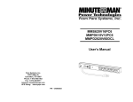
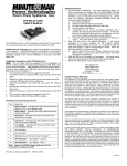
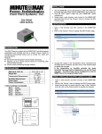
Remote Power Manager
RPM1521
User’s Manual
RPM1521
Table of Contents
1. Product Introduction ...................................................................................................2
1-1 Applications .........................................................................................................2
1-2 Power Control and Monitoring Diagram...............................................................3
1-3 Product Features .................................................................................................4
1-4 Control and Indicators .........................................................................................5
1-5 Specifications.......................................................................................................6
1-6 Package Contents ...............................................................................................7
2. Installation and Setup..................................................................................................8
2-1 Hardware Installation ..........................................................................................8
2-2 Setup Procedure .................................................................................................9
3. Web Operation .............................................................................................................11
3-1 System Login.......................................................................................................11
3-2 Monitor Tab..........................................................................................................12
3-2-1 Power Switch Operation...........................................................................13
3-2-2 Configuration ............................................................................................14
3-2-3 Schedule ..................................................................................................15
3-2-4 Network ....................................................................................................15
3-3 System Tab..........................................................................................................16
3-3-1 Network....................................................................................................16
3-3-2 Mail Server...............................................................................................17
3-3-3 SMS Server .............................................................................................18
3-3-4 SNMP/SysLog .........................................................................................19
3-3-5 Other........................................................................................................20
3-4 Firewall Tab .........................................................................................................21
3-4-1 IP Filter.....................................................................................................21
3-4-2 MAC Filter ................................................................................................22
3-5 Account Tab.........................................................................................................23
3-6 TimeSync Tab......................................................................................................24
3-7 Event Tab ............................................................................................................25
3-8 Upgrade Tab........................................................................................................26
3-9 Logout Tab...........................................................................................................26
Appendix...........................................................................................................................27
A1 Firmware Upgrade ...............................................................................................27
A2 Reset to Default ...................................................................................................29
A3 Obtaining Technical Support.................................................................................30
A4 Limited Product Warranty .....................................................................................31
© Copyright 2009
1
RPM1521
1. Product Introduction
The RPM1521 is an Internet ready SNMP device designed with integrated versatile
functions including power control, remote web administration, event alerts into one single
unit, which helps system administrators or IT personnel to monitor and control their
connected equipment and take preventive measures when needed.
Allows an
administrator to remotely control the AC power for two connected devices, such as:
servers, routers, modems, DVRs, security and telephone equipment.
The RPM1521 offers; easy set up, user-friendly communications and control methods.
Easily connects to the LAN using normal Ethernet connection. Once connected and
properly set up, the administrator can manage the AC power of the devices from anywhere
in the world via a web browser, which greatly reduces the need for on-site service.
Additional benefits from employing this intelligent power distribution system including:
•
•
•
Improves administrative efficiencies with remote power monitoring and control
Reduces system down time without dispatching service personnel to remote locations
Monitoring and management from anywhere in the world
1-1 Applications
•
•
•
•
•
Monitoring and management of the computer equipment room.
Intelligent power management of data center and networking equipments.
Power scheduling of machinery equipment for the factory building.
Home appliance power control and monitoring.
Other power equipment management, scheduling and monitoring.
2
RPM1521
1-2 Power Control and Monitoring Diagram
This is a typical application for the RPM1521.
3
RPM1521
1-3 Product Features
• IP-addressable Remote Power Manager with built-in web server and 2 power outlets.
• Control power equipment remotely via the Internet without the presence of service
personnel.
• Manual power ON/OFF button to completely power down the RPM1521.
• Each AC power outlet can be independently switched ON/OFF, power cycled for
immediate reboots or rebooted with timed delays, power cycle sequencing with
assigned priority and power event scheduling.
• LEDs for power status and control mode indication.
• Supports Power Start sequencing to prevent all of the connected devices from starting
simultaneously to limit the in-rush current to the RPM.
• Easy web setup for scheduling daily, weekly, monthly and yearly power operations on a
specific outlet.
• The Auto-Ping feature will monitor and auto detect any failed network equipment and
perform a timed reboot.
• IP filter/mask function helps manage user privileges and prevent unauthorized access
to the control menu through the network.
• Instant email, SMS text messages and trap notification will be generated when power
events occurred.
• Overload and connected equipment protection via the input circuit breaker.
• Rack mountable design with holes on the side of the metal enclosure for an optional
rack-mounting kit.
• Provides Surge protection to eliminate disrupting and damaging effects of momentary
voltage spikes or impulses from other power transients.
4
RPM1521
1-4 Control and Indicators
1
2
3
LED #1 is illuminated when output receptacle #1 is ON.
LED #2 is illuminated when output receptacle #2 is ON.
Reset LED will flash when the Reset function is being performed.
Utility Power LED is illuminated when there is an acceptable AC
voltage present.
4
RJ45 Ethernet Port for connecting to the network.
5
Power Switch & Breaker Protection.
6
Utility Power Inlet.
7
Output Receptacles.
5
RPM1521
1-5 Specifications
Number of Phase
Input & Output Voltage
Single (1Ø 2W + G)
100 - 120VAC
Input & Output Frequency
47 - 63Hz
Total Output Current (max)
12 Amp (at 120V)
Surge Energy Rating
Input Protection
Operating Temperature
Storage Temperature
Operating/Storage Humidity
1200 J
Re-settable Power Switch/Breaker
0 – 60ºC (+32 - +140ºF)
-15 to +45°C (+5 to +113°F)
0 - 95% Non-Condensing
Operating Elevation
0 to 3,000m (0 to +10,000 ft)
Storage Elevation
0 to 15,000m (0 to +50,000 ft)
Utility Power Inlet
IEC 320 C14
Output Receptacles
NEMA 5-15R
Net Dimensions
(W x D x H)
Net Weight
Shipping Dimensions
(W x D x H)
Shipping Weight
Regulatory
7.17 x 4.90 x 1.70”
182 x 125 x 44mm
1.78 lbs
0.806 kgs
9.6 x 8.5 x 3.1”
245 x 217 x 80mm
2.78 lbs
1.26 kgs
CE Certified
6
RPM1521
1-6 Package Contents
Remote Power Monitor * 1
CD Rom with User’s Manual * 1
Power Cord * 1
7
RPM1521
2. Installation and Setup
2-1 Hardware Installation
1.
2.
3.
4.
Connect the power cord to the power inlet on the RPM and to the utility service.
Plug the equipment into the output receptacles.
Connect the Ethernet cable to the Ethernet port.
Turn the power switch to the ON position.
8
RPM1521
2-2 Setup-Procedure
The minimum requirement to operate the RPM1521 is to setup the IP Address, subnet
mask, and the gateway. The IP Search Utility program supports most Windows
Operating Systems (Windows NT4.0, 2000, 2003, XP, Vista).
There are two ways to perform the Setup-Procedure:
1. Open a web browser and input the default IP address.
and input the information.
2. Use the IP Search Utility program (on the CD).
Then open the Network page
The default settings are:
IP address: 192.168.1.10
Subnet mask: 255.255.255.0
Gateway address: 192.168.1.1
Account name: admin (lower case)
Password: admin (lower case)
1. The workstation and the RPM1521 must be in the same LAN to perform the
Setup-Procedure.
2. The Windows Firewall must be turned off to operate the IP Search Utility program.
3. From the Start menu select the Control Panel.
4. Select the Windows Firewall.
5. Select Off and then click the OK button.
6. Put the RPM1521’s CD (provided) in the CD-ROM drive.
7. Launch the IP Search Utility program.
9
RPM1521
8. Click on the Refresh button to search for all of the RPM1521’s in the LAN. A list of the
RPM1521s will be displayed.
9. Click on the RPM1521. Configure the IP address, the Gateway and the NetMask
(Subnet) and then click on the Configure button twice. You will see the IP address, the
Gateway and the NetMask (Subnet) for the selected RPM1521 in the list change.
10. Repeat Step number 8 and 9 for all of the RPM1521 in the list.
11. Once all of the RPM1521s are setup, close the IP Search Utility program and turn the
Windows Firewall back on.
12. This completes the initial Setup-Procedure of the RPM1521.
13. Now you are able to monitor and control the RPM1521 via a Web Browser.
10
RPM1521
3. Web Operation
3-1
System Login
1. Open a Web Browser (Internet Explore, Firefox).
2. Enter the RPM1521’s IP Address.
3. Enter the Account name (admin) and Password (admin).
NOTE: The Account name and the Password are lower case.
11
RPM1521
3-2
Monitor Tab
You can set up each individual outlet on the Monitor tab as illustrated in the following
sections.
12
RPM1521
3-2-1 Power Switch Operation
Double clicking with the left mouse button on the ALL ON button will turn ON all of the
outlets. Double clicking with the left mouse button on the ALL OFF button will turn OFF
all of the outlets.
Double clicking with the left mouse button on one of the bottom buttons will turn ON that
individual outlet or turn OFF that individual outlet.
If you want to reboot the individual
outlet check the Reboot box and then double click with the left mouse button on the
bottom button to reboot the outlet.
Button Illustration:
ON
OFF
Not Authorized
No Power
13
RPM1521
3-2-2 Configuration
Set: Click on the Set button located on the top corner of the outlet to setup that individual
outlet. When the Set button is orange, the outlet is ready to be configured.
Description: The users can assign a name to each individual outlet. This allows the
system administrator and/or manager to easily distinguish between the equipment that is
connected to the outlets.
Start Delay Time: Each outlet can be programmed to startup at different time intervals
instead of both of them starting up at the same time.
Shutdown Delay Time: Each outlet can be programmed to shutdown at different time
intervals instead of shutting both of them down at the same time.
Save: Once the setup is complete click the Save button to save all of the changes.
14
RPM1521
3-2-3 Schedule
Click the Set button located on the top corner of the outlet to setup a Schedule for that
individual outlet to turn ON/OFF or Reboot on a certain day at a specific time. When the
Set button is orange, the outlet is ready to be configured.
Recurrence: An Action can be schedule to occur yearly, monthly, weekly or daily at a
specific time for each individual outlet.
Time: Set the time (hours and minutes) when you want the Action to occur to an outlet.
Action: Set the action you want the outlet to perform, ON, OFF or Reboot.
ADD: Click the ADD button to add this action.
Delete: To delete a schedule, double-click on the “X”.
Save: Once the setup is complete click the Save button to save all of the changes.
3-2-4 Network
Click the Set button located on the top corner of the outlet to setup the Auto-Ping feature.
The RPM1521 can be setup to ping an IP-addressable device and detect when that device
has stopped communicating. If the Reboot action is selected the power to the connected
device will be cycled OFF and then ON. After the preset time the Auto-Ping function will
restart.
Detect: Check this box to enable the Auto-Ping function.
Equipment Network Address: Enter the IP address of the connected equipment.
PING Interval Time: Set the time Interval to PING the connected device.
Detect Times: If a device fails to respond to a ping continuously and exceeds the preset
time, the RPM1521 will notify the selected personnel via email or SMS.
Reboot: Check this box to reboot the outlet for the failed connected device.
Re-detect Time: The time interval before restarting the Auto-Ping function after the
connected device has been rebooted.
Save: Once the setup is complete click the Save button to save all of the changes.
15
RPM1521
3-3
System Tab
3-3-1 Network
The RPM1521 can be configured with a Static IP address or setup to use DHCP.
The default settings are:
Static IP address
IP address: 192.168.1.10
Subnet mask: 255.255.255.0
Gateway address: 192.168.1.1
IP Address: Enter the IP address.
Subnet Mask: Enter the Subnet Mask.
Gateway: Enter the Gateway address.
DNS Server 1: Enter your primary DNS server (if required).
DNS Server 2: Enter your secondary DNS server (if required).
Http Port: Assign the desired HTTP port (default is port 80) for connecting to the RPM1521
via a web browser. The HTTP port can be changed if so desired. An example would be
HTTP port 8080.
Enter the IP address followed by the new HHTP port
(http://192.168.1.10:8080).
API Port: The Application Program Interface Port allows the user to interface and control
the RPM1521 with their own application program.
Save: Once the setup is complete click the Save button to save all of the changes.
16
RPM1521
3-3-2 Mail Server
This menu allows the administrator to configure the email setting to send notifications once
an event has occurred.
SMTP Server Address: Enter the Hostname or IP address of the SMTP Mail Server that
will be used to send emails from the RPM1521. If entering a Hostname, you are also
required to enter the DNS Address.
SMTP Port: Enter the port number for the SMTP server. The default port is 25.
Sender Mail Address: This must be a legitimate email address.
Mail Subject: When an event occurs the RPM1521 will send an email notification. The
subject line can be setup to easily identify that device.
SMTP Auth: Check this box if the Mail Server requires authentication to send emails.
SMTP Account: Enter the account name if SMTP authentication is required.
SMTP Password: Enter the password if SMTP authentication is required.
Mail Test: This is used to verify that the email works properly.
Save: Once the setup is complete click the Save button to save all of the changes.
17
RPM1521
3-3-3 SMS Server
This menu allows the administrator to configure the SMS setting to send notifications once
an event has occurred.
Server Address: Enter the SMS server address.
Port: Enter the port number for the SMS server. The default value is 2500.
Equipment Name: When an event occurs the RPM1521 will send an SMS notification. The
equipment name will identify the device.
Account: Enter the account name if required.
Password: Enter the password if required.
Send SMS: Check this box if SMS Server requires authentication to send messages.
SMS Test: This is used to verify that the SMS works properly.
Save: Once the setup is complete click the Save button to save all of the changes.
18
RPM1521
3-3-4 SNMP/SysLog
This menu allows the administrator to configure the RPM1521 to send SNMP Traps and
System Logs to different Network Management Stations (NMS).
System Name: Enter the name of the SNMP device.
System Contact: Enter the name of the System Administrator.
System Location: Enter the location of the SNMP device.
Receiver IP Address: The IP Address of the NMS of where the Traps should be sent.
Receiver Port: The port that will be used to receive the Traps. The default value is 162.
Community: Low-level password of the associated IP address with the access type set by
the administrator.
Enabled: Enables the SNMP Traps to be sent.
SNMP Test: This is used to verify that the Trap notification works properly.
Syslog Server Address: The IP Address of the Server to which the System Logs should be
sent.
Syslog Server Port: The port that will be used to receive the System Logs.
Enabled: Enables the System Logs to be sent.
SYSLOG Test: This is used to verify that the SYSLOG works properly.
Save: Once the setup is complete click the Save button to save all of the changes.
19
RPM1521
3-3-5 Other
This menu allows the administrator to configure the outlets to reboot, set the operational
time, and perform an immediate reboot of the outlets.
Reboot Option: This allows the user to reboot the outlet instead of just turning the outlet
ON/OFF. The Reboot check box on the Monitor screen will be checked when this option
is selected.
Operational Idle Time: The time interval between no activity and when the user will be
logged out.
Reboot Device: Selecting this option will immediately reboot the outlets.
Save: Once the setup is complete click the Save button to save all of the changes.
20
RPM1521
3-4
Firewall Tab
3-4-1 IP Filter
This menu allows the administrator to configure the users privileges and prevent
unauthorized access to the RPM1521 through the network.
Allow IP Address: The first four sections are the beginning of the IP range. The last section
is the ending of the IP range, which the administrator has given specific rights to certain
users to access the RPM1521. Example to authorize the IP ranges of 192.168.1.100 to
192.1681.200, input 192.168.1.100 in the first four sections and then input 200 in the last
section. If you only want to authorize one IP address, then input 192.168.1.100 in the first
four sections and then input 100 in the last section. The default IP address range is the IP
address of the computer that you initially use to view the RPM1521.
ADD: Click the ADD button to add this action.
Delete: To delete a specific IP address click on the “X”.
Save: Once the setup is complete click the Save button to save all of the changes.
21
RPM1521
3-4-2 MAC Filter
This menu allows the administrator to configure the users privileges and prevent
unauthorized access to the RPM1521 through the network.
Allow MAC Address: The administrator can give specific rights to certain users to access the
RPM1521. Enter the MAC address of the user that you want to have access to the
RPM1521. The default MAC address is the MAC address of the computer that you initially
use to setup the RPM1521.
ADD: Click the ADD button to add this action.
Delete: To delete a specific MAC address click on the “X”.
Save: Once the setup is complete click the Save button to save all of the changes.
22
RPM1521
3-5
Account Tab
This menu allows the administrator to setup authorized user accounts and other privileges.
The administrator can assign specific access levels for each user account. Example: The
administrator can assign user “A” to have access to outlet number 1 and receive email
notifications when an event occurs to that specific outlet.
Account: Enter the user id for each user account.
Password: Enter the password for each user account.
Cell phone: Enter the contact phone number of the user that will receive the SMS text
message once an event has occurred.
Mail Address: Enter the contact email address of the user that will receive the email
notification once an event has occurred.
Delete: Check the delete box and then click on the Delete button to delete this user
account, you must press the Save button to save the changes.
Save: Once the setup is complete click the Save button to save all of the changes.
23
RPM1521
3-6
TimeSync Tab
This menu allows the administrator to set the date and time for the RPM1521.
Equipment Date: Displays the date. This field is not editable.
Equipment Time: Displays the time in 24-hour format. This field is not editable.
Sync with PC: Check the Sync with PC button to synchronize the RPM1521’s date and
time with the PC.
PC Date: The current PC system date.
PC Time: The current PC system time.
Sync with NTP Server: Check the Sync with NTP Server button to synchronize the
RPM1521’s date and time with a NTP server.
NTP Server Address: There is a list of some of the available NTP servers. Select the
desired NTP server and then click Save. If your desired NTP server is not on the list, click
on the New button and then enter the NTP server address, then click OK.
Manual Setup: Check the Manual Setup button to manually setup the date and time.
Save: Once the setup is complete click the Save button to save all of the changes.
24
RPM1521
3-7
Event Tab
This menu displays the events that have occurred with the RPM1521.
Refresh: Click on the Refresh button to refresh the screen.
Download: Click on the Download button to save the event log information. The event log
is saved in .txt format.
Delete: Click on the Delete button to delete the Event logs.
25
RPM1521
3-8
Upgrade Tab
This menu allows the administrator to download the configuration (settings) of one
RPM1521 and then upload it to another RPM1521.
The Download Configuration procedure:
1. Click on the Download button.
2. Select the location to save the file. The download file is saved in a .bin format.
The Upload Configuration procedure:
1. Click on the Browse button.
2. Select the cfg.bin file.
3. Click on the Open button.
4. Click on the Upload button.
5. Once the Upload is complete the RPM1521 will automatically reboot.
3-9
Logout Tab
Click on the Logout Tab to logout of the RPM1521.
26
RPM1521
Appendix
A1 Firmware Upgrade
This menu allows the administrator to upgrade the firmware of the RPM1521.
Firmware Upgrade Procedure:
1. Open the firmware_upgrade.exe program located on the RPM1521 CD.
2. Input the IP Address of the RPM1521.
3. Click on the GetVersion button.
4. Click on the browse (…) button to search for the new firmware file (.bin).
5. Input the password (default is admin).
27
RPM1521
6. Click on the Upgrade button to start the firmware upgrading process.
7. Once the firmware upgrading process is complete the RPM1521 will reboot.
8. Once the reboot is complete click the OK button.
9. This completes the Firmware Upgrade process.
28
RPM1521
A2 Reset to Default
If you forgot the password and/or the user name the RPM1521 can be reset back to the
manufacturer’s default setting.
The Reset button is located in the small hole next to the Reset indicating light. Insert a
pointed object like a paper clip into this hole. Gently push and hold the reset button for at
least 3-seconds, then release the reset button.
The IP address will be reset back to 192.168.1.10
The user name and password will be reset back to admin.
All of the other setting will be unchanged.
29
RPM1521
A3 Obtaining Technical Assistance
For Technical Support on the Web, please visit the Support section of our Web site or visit our online Discussion
Forum. In order to diagnose the problem you are having, our technicians need the following information from you.
Installation Site:
Company Name:
Address:
City:
State:
ZIP code:
Contact Person’s Name:
Phone Number:
If you are a consultant,
Consultant Name:
Phone Number:
Fax Number:
RPM:
Model Name/Number:
Serial Number:
NMS name and revision number:
What are the symptoms?
Please have the information listed above ready when you contact us.
Contact Technical Support By:
Phone:
1-800-238-7272 / 1-972-446-7363
Fax:
1-972-446-9011
Web:
www.minutemanups.com/support/index.php (Technical Support)
www.minutemanups.com/phpBB2/index.php (Discussion Board)
www.minutemanups.com (Home Page)
30
RPM1521
A4 Limited Product Warranty
Para Systems Inc. (Para Systems) warrants this equipment, when properly applied and operated within specified
conditions, against faulty materials or workmanship for a period of three years from the date of original purchase by
the end user. For equipment sites within the United States and Canada, this warranty covers repair or replacement
of defective equipment at the discretion of Para Systems. Repair will be from the nearest authorized service center.
Replacement parts and warranty labor will be borne by Para Systems. For equipment located outside of the United
States and Canada, Para Systems only covers faulty parts. Para Systems products repaired or replaced pursuant
to this warranty shall be warranted for the remaining portion of the warranty that applies to the original product.
This warranty applies only to the original purchaser who must have properly registered the product within 10 days
of purchase.
The warranty shall be void if (a) the equipment is damaged by the customer, is improperly used, is subjected to an
adverse operating environment, or is operated outside the limits of its electrical specifications; (b) the equipment is
repaired or modified by anyone other than Para Systems or Para Systems-approved personnel; or (c) has been
used in a manner contrary to the product's operating manual or other written instructions.
Any technical advice furnished before or after delivery in regard to use or application of Para Systems’ equipment
is furnished without charge and on the basis that it represents Para Systems’ best judgment under the
circumstances, but it is used at the recipient's sole risk.
EXCEPT AS PROVIDED HEREIN, PARA SYSTEMS MAKES NO WARRANTIES, EXPRESSED OR IMPLIED,
INCLUDING WARRANTIES OF MERCHANTABILITY AND FITNESS FOR A PARTICULAR PURPOSE. Some
states do not permit limitation of implied warranties; therefore, the aforesaid limitation(s) may not apply to the
purchaser.
EXCEPT AS PROVIDED ABOVE, IN NO EVENT WILL PARA SYSTEMS BE LIABLE FOR DIRECT, INDIRECT,
SPECIAL, INCIDENTAL, OR CONSEQUENTIAL DAMAGES ARISING OUT OF THE USE OF THIS PRODUCT,
EVEN IF ADVISED OF THE POSSIBILITY OF SUCH DAMAGE. Specifically, Para Systems is not liable for any
costs, such as lost profits or revenue, loss of equipment, loss of use of equipment, loss of software, loss of data,
cost of substitutes, claims by third parties, or otherwise. The sole and exclusive remedy for breach of any warranty,
expressed or implied, concerning Para Systems’ products and the only obligation of Para Systems hereunder, shall
be the repair or replacement of defective equipment, components, or parts; or, at Para Systems’ option, refund of
the purchase price or substitution with an equivalent replacement product. This warranty gives you specific legal
rights and you may also have other rights, which vary from state to state.
34000375
31