1
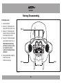
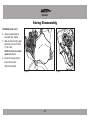
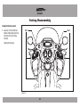
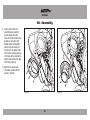
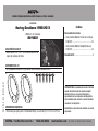
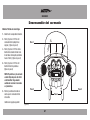
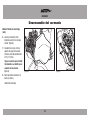
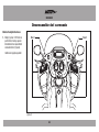
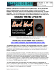
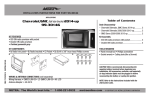
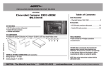
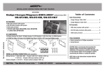
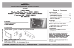
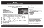
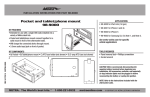
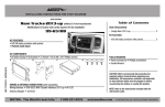
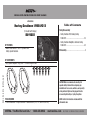
INSTALLATION INSTRUCTIONS FOR PART 82-9601
APPLICATIONS
Table of Contents
Harley-Davidson 1998-2013
Fairing Disassembly
(FL models with fairings)
– Harley-Davidson FLH, batwing fairing
... 1998-2013 .......................................................2-3
82-9601
– Harley-Davidson Roadglide, sharknose fairing
... 1998-2013 .......................................................4-5
KIT FEATURES
• Mounts aftermarket 6.5” to 6.75” speakers into
factory speaker locations.
Kit Assembly .......................................................... 6
KIT COMPONENTS
• A) (2) speaker adapters • B) (6) #8 x 1” Pan-head Phillips screws
REV. 4/14/2014 INST82-9601
A
B
CAUTION: Metra recommends disconnecting the
negative battery terminal before beginning any
installation. All accessories, switches, and especially
air bag indicator lights must be plugged in before
reconnecting the battery or cycling the ignition.
TOOLS REQUIRED
• Panel removal tool • Phillips screwdriver • Socket Wrench (T-25, T-27, 6mm or 3/16 hex)
METRA. The World’s best kits.™
1-800-221-0932
NOTE: Refer to the instructions included with the
aftermarket radio.
metraonline.com
© COPYRIGHT 2014 METRA ELECTRONICS CORPORATION
82-9601
Fairing Disassembly
FLH/Batwing models:
1. Cover the front fender.
2. Remove (2) T-27 Torx bolts from inner
fairing (under mirrors) (Figure A, step 2)
Step 4
3. Remove (2) T-27 Torx bolts from outer
edges of inner fairing near the fork tubes
(facing forward) (Figure A, step 3)
4. Remove (3) T-27 Torx bolts from bottom
edge of windshield. (Figure A, step 4)
NOTE: Windshield and fairing
will be loose once these screws
are removed. Use extreme
caution not to damage fairing or
windshield.
5. Remove windshield taking caution that
the outer fairing is loose.
Continued on next page
Step 2
Step 2
Step 3
(Figure A)
2
82-9601
Fairing Disassembly
FLH/Batwing models: (cont.)
6. Lift away and unplug headlight to
remove outer fairing. (Figure B)
7. Unbolt and remove inner fairing support
brackets from each side (3/16” Allen &
T-25 Torx screws)
Note the Torx screw is also a shared
speaker screw. (Figure C)
8. Remove the remaining speaker
screws and the speaker.
Continue to kit assembly
(Figure B)
(Figure C)
3
82-9601
Fairing Disassembly
Roadglide/Sharknose models
1. Loosen (6) T-25 Torx bolts from
bottom, middle and top of left and
right sides of the inner fairing.
(Figure A)
Step 1
Step 1
Continued on next page
(Figure A)
4
82-9601
Fairing Disassembly
Roadglide/Sharknose models: (cont.)
2. Use a 1/2” socket or box wrench to
remove the (2) acorn nuts that hold
each turn signal at the lower fairing.
Let the signals hang loose.
(Figure B)
3. Lift away the fairing, unplug the
headlights and remove.
4. Remove the speaker screws
and the speaker.
Continue to kit assembly
(Figure B)
5
82-9601
Kit Assembly
1. Using 3 of the screws in the
provided hardware, mount the
speaker adapter to the inner
fairing. The 4th inner bottom screw
locations are not used on FLH/
batwing models. For Road Glide
models, rotate the adapter until
the notches in the adapter do not
hit the factory mounting posts and
the flat spots on the outside of the
adapter are toward the outer edge
of the fairing. (Figure A)
2. Mount the new speaker with
the hardware provided with the
speakers. (Figure B)
(Figure A)
(Figure B)
6
82-9601
INSTALLATION INSTRUCTIONS FOR PART 99-9601
KNOWLEDGE IS POWER
REV. 4/14/2014 INST82-9601
Enhance your installation and fabrication skills by
enrolling in the most recognized and respected
mobile electronics school in our industry.
Log onto www.installerinstitute.com or call
800-354-6782 for more information and take steps
toward a better tomorrow.
Metra recommends MECP
certified technicians
METRA. The World’s best kits.™
1-800-221-0932
metraonline.com
© COPYRIGHT 2014 METRA ELECTRONICS CORPORATION
INSTRUCCIONES DE INSTALACIÓN PARA LA PIEZA 82-9601
AplicAciones
Indice
Harley-Davidson 1998-2013
Desensamble del carenado
(Modelos FL con carenados)
82-9601
– Harley-Davidson Modelos FLH/alas de murciélago
... 1998-2013 .......................................................2-3
– Harley-Davidson Modelos Roadglide/Sharknose
... 1998-2013 .......................................................4-5
cArActerísticAs del kit
• Monta bocinas de 6.5” a 6.75” de mercado secundario en los
lugares de las bocinas de fábrica.
Ensamble del kit .................................................... 6
componentes del kit
• A) (2) adaptadores de bocinas • B) (6) tornillos Phillips de cabeza troncocónica #8 x 1”
REV. 4/14/2014 INST82-9601
A
B
PRECAUCIÓN: Metra recomienda desconectar el terminal
negativo de la batería antes de comenzar cualquier
instalación. Todos los accesorios, interruptores y,
especialmente, las luces indicadoras de airbag deben
estar enchufados antes de volver a conectar la batería o
comenzar el ciclo de ignición.
HerrAmientAs requeridAs
• Herramienta para quitar paneles • Destornillador Phillips • Llave de tubo (T-25, T-27, 6 mm, 3/16 hex)
METRA. The World’s best kits.™
1-800-221-0932
Nota: Remítase a las instrucciones incluidas con el radio
de posventa.
metraonline.com
© COPYRIGHT 2014 METRA ELECTRONICS CORPORATION
82-9601
Desensamble del carenado
Modelos FLH/alas de murciélago
1. Cubierta de la salpicadera delantera
2. Retire (2) pernos T-27 Torx del
carenado interior (abajo de los
espejos). (Figura A, paso 2)
Paso 4
3. Retire (2) pernos T-27 Torx de los
bordes del carenado interior cerca
de los tubos de horquilla (orientado
hacia el frente) (Figura A, paso 3)
4. Retire (3) pernos T-27 Torx del
borde inferior del parabrisas.
(Figura A, paso 4)
NOTA: El parabrisas y el carenado
estarán flojos después de retirar
estos tornillos. Tenga mucho
cuidado de no dañar el carenado
o el parabrisas.
Paso 2
5. Retire el parabrisas teniendo en
cuenta que el carenado exterior
está suelto.
Continúa en la página siguiente
Paso 2
Paso 3
(Figura A)
2
82-9601
Desensamble del carenado
Modelos FLH/alas de murciélago
(cont.)
6. Levante y desconecte el faro
delantero para retirar el carenado
exterior. (Figura B)
7. Desatornille el perno y retire los
soportes de apoyo del carenado
interior en cada lado (tornillos Allen
3/16” y T-25 Torx).
Tenga en cuenta de que el tornillo
Torx también es un tornillo que se
comparte con las bocinas.
(Figura C)
(Figura B)
(Figura C)
8. Retire los tornillos restantes de la
bocina y la bocina.
Continúe kit de montaje
3
82-9601
Desensamble del carenado
Modelos Roadglide/Sharknose
1. Afloje (6) pernos T-25 Torx de la
parte inferior, media y superior
del lado derecho e izquierdo del
carenado interior. (Figura A)
Paso 1
Paso 1
Continúa en la página siguiente
(Figura A)
4
82-9601
Desensamble del carenado
1.
Modelos Roadglide/Sharknose
(cont.)
2. Use una llave de cubo de 1/2” para
retirar las (2) tuercas ciegas que
sostienen cada señal direccional en
el carenado inferior. Deje colgando
las señales direccionales.
(Figura B)
2.
3. Levante el carenado, desconecte
los faros delanteros y retírelos.
3.
4. Retire los tornillos de la bocina
y la bocina.
4.
Continúe kit de montaje
(Figura B)
5
82-9601
Ensamble del kit
1. Use 3 de los tornillos que
vienen en la tornillería, monte
el adaptador de bocina en el
carenado interior. Los lugares del
4o tornillo inferior interior no se
usan en los modelos FLH/ala de
murciélago. Para los modelos Road
Glide, gire el adaptador hasta que
las muescas en él no golpeen con
los postes de montaje de fábrica
y las partes planas externas del
adaptador estén orientadas hacia
el borde exterior del carenado.
(Figura A)
2. Monte la nueva bocina con la
tornillería suministrada con las
bocinas. (Figure B)
(Figura A)
(Figura B)
6
82-9601
7
INSTRUCCIONES DE INSTALACIÓN PARA LA PIEZA 82-9601
EL
CONOCIMIENTO
ESOWER
PODER
K
NOWLEDGE
IS P
Mejore sus habilidades de instalación y fabricación
REV. 4/14/2014 INST82-9601
Enhance your installation and fabrication skills by
enrolling
in the en
most
recognized
and respected
inscribiéndose
la escuela
de dispositivos
electrónicos
mobile
school
in our industry.
móvileselectronics
más reconocida
y respetada
de nuestra industria.
Log
onto www.installerinstitute.com
or call
Regístrese
en www.installerinstitute.com
o llame al
800-354-6782 for more information and take steps
800-354-6782 para obtener más información y avance
toward a better tomorrow.
hacia un futuro mejor.
Metra recomienda técnicos
con certificación del Programa
de Certificación en Electrónica
Móvil (Mobile Electronics
Certification Program, MECP).
METRA. The World’s best kits.™
1-800-221-0932
metraonline.com
© COPYRIGHT 2014 METRA ELECTRONICS CORPORATION