1
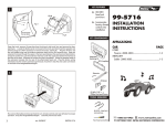
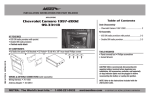
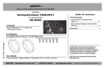
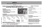
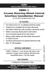
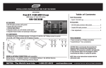
INSTALLATION INSTRUCTIONS FOR PART 99-7803G
APPLICATIONS
Table of Contents
Honda Accord 2003-2007
(non-NAV models)
Dash Disassembly
99-7803G
– Honda Accord 2003-2007 .................................2-3
Kit Assembly
KIT FEATURES
• Double DIN radio provisions
• ISO DIN radio provisions with pocket
• Retains all climate control systems including dual-zone
• Painted gray to match the factory finish
– Double DIN radio provisions ..............................3-4
– ISO DIN radio provisions with pocket .................4-5
Wiring Instructions
REV. 11/29/2012 INST99-7803G
KIT COMPONENTS
• A) Radio Housing Trim Panel • B) Radio Brackets • C) Pocket • D) Panel Clip Legs • E) (2) Panel Clips
• F) (2) Speed clips • G)(2) #10 x ¾” Phillips screws • H) (4) #4 x 3/8” Phillips screws
• I) (8) #8 x 3/8” truss head screws (four for pocket, four for brackets to housing) • Wiring Harness
A
B
C
F
G
D
H
– Programming ....................................................... 7
E
I
WIRING & ANTENNA CONNECTIONS (sold separately)
Wiring Harness: • Included
Antenna Adapter: • Not Required
TOOLS REQUIRED
• Panel removal tool • Phillips screwdriver • Socket Wrench
METRA. The World’s best kits.™
– Wiring Instructions ............................................... 6
1-800-221-0932
CAUTION: Metra recommends disconnecting the
negative battery terminal before beginning any
installation. All accessories, switches, and especially
air bag indicator lights must be plugged in before
reconnecting the battery or cycling the ignition.
NOTE: Refer to the instructions included with the
aftermarket radio.
metraonline.com
© COPYRIGHT 2004-2011 METRA ELECTRONICS CORPORATION
99-7803G
Dash Disassembly
1. Unsnap and remove shift lever trim
ring. (Figure A)
4. Remove (2) Phillips screws from
bottom of pocket assembly and
unsnap and remove. (Figure D)
2. Unsnap coin tray/ashtray from
assembly and remove. Rubber
cover may come out first but entire
assembly must be removed to
access screws below. (Figure B)
3. Remove (2) Phillips screws from
under coin tray/ashtray and
remove entire assembly. (Figure C)
5. Remove (2) Phillips screws facing
up under radio/climate control
assembly.) (Figure E)
R
N
D
D
6. Push and hold the hazard button
down. Carefully insert a flat blade
screwdriver into the slot below the
button and push down to release
the center clip. (Figure F)
(Figure A)
P
R
(FigureDND)
D
Continued on next page
R
N
D
D
(Figure B)
(Figure C)
(Figure E)
R
N
D
D
(Figure F)
2
99-7803G
Dash Disassembly
Kit Assembly
7. Unsnap and remove upper panel
(including a/c vents) and remove
(3) Phillips screws behind the
panel. (Figure G)
Tip: You can use a hook tool to
grasp the panel inside of the vent
and pull toward the rear of the
vehicle. Be careful not to
scratch the panel.
Double DIN head unit provisions
1. Mount the radio brackets to the
radio trim panel with four of the
supplied #8 screws. (Figure A)
Continue to kit assembly
Continued on next page
(Figure G)
Step 1.
8. Unclip and remove radio/climate
control assembly.
9. Cut and remove the center section
of the dash cavity. (Figure H)
Be sure to leave the outside clip
slots intact. (See detail)
2. Slide the DDIN aftermarket radio
into the kit assembly and secure
with screws supplied with the
radio. (Figure A)
Step 2.
Remove shaded area
(Figure H)
Cut close without
cutting into clip slot
(Detail)
(Figure A)
3
99-7803G
Kit Assembly
Double DIN head unit provisions
3. Mount the (2) panel clip legs to the
radio trim panel with the provided
(4) #4 Phillips screws. Attach the
(2) panel clips to the legs.
(Figure B)
4. Locate the factory wiring harness
and antenna plug in the dash.
Refer to the wiring section of
this manual.
ISO DIN head unit provisions
1. Mount the pocket to the radio
brackets with four of the supplied
#8 x 3/8” Phillips screws. (Figure A)
5. Mount the new aftermarket radio
assembly into the dash and
reassemble dash in reverse order
of disassembly.
2. Mount the radio brackets to the
radio trim panel with four of the
supplied #8 screws. (Figure A)
Continued on next page
Step 1.
Step 2
Clip leg locations
(Figure B)
(Figure A)
4
99-7803G
Kit Assembly
5. Locate the factory wiring harness
and antenna plug in the dash.
Refer to the wiring section of
this manual.
3. Slide the radio into the kit
assembly and secure with screws
supplied with the unit. (Figure B)
4. Mount the (2) Panel Clip Legs
to the Radio Trim Panel with the
provided (4) #4 Phillips screws.
Attach the (2) Panel Clips to the
legs. (Figure C)
6. Mount the included speed clips to
the bottom mounting legs of the
radio brackets. (Figure D)
7. Mount the new radio assembly
into the dash, use the two included
#10 screws for the bottom support
screw and reassemble dash in
reverse order of disassembly.
(Figure B)
Note: The door on the factory
pocket below the radio will not
function properly with this new
kit installed. As an alternate
solution, Metra offers the
88-00-7803 replacement
pocket sold separately.
Clip leg locations
(Figure C)
5
(Figure D)
99-7803G
Wiring Instructions
From the 20-pin harness:
• Connect the Red wire to the ignition
wire of the aftermarket radio.
• Connect the Yellow wire to the
radio’s 12-volt battery or
memory wire.
This 12-pin harness is to be used in
conjunction with the ASWC (not included).
• Connect the Gray wire to the right
front positive speaker output of the
aftermarket radio
• Connect the Black wire to the
radio’s ground wire.
• Connect the Gray/Black wire to the
right front negative speaker output
of the aftermarket radio.
• Connect the Blue wire to the
antenna turn on wire of the
aftermarket radio.
• Connect the Green wire to the
radio’s left rear positive
speaker output.
• Connect the Orange wire to the
illumination wire of the aftermarket
radio. If the aftermarket radio has
no illumination wire just tape off the
Orange/White wire.
• Connect the Green/Black wire
to the radio’s left rear negative
speaker output.
• Connect the White wire to the left
front positive speaker output of the
aftermarket radio
Additional 12-pin harness
(ASWC harness)
• Connect the White/Black wire
to the left front negative speaker
output of the aftermarket radio.
Please refer to ASWC instructions for
programming. The ASWC is to retain
the factory steering wheel controls
if equipped.
Plug the 6-pin side into the 99-7803 and
the 20-pin into the vehicle radio harness.
Caution:
The car will only be manual or auto
climate. This kit should come with
covers over the climate control plug
locations. Be sure to plug auto climate
cars into the appropriate auto climate
location on the 99-7803 installation
kit. Be sure to plug the manual climate
cars into the appropriate manual
climate location on the 99-7803
installation kit. (Figure A, next page)
• Connect the Purple wire to the
radio’s right rear positive
speaker output.
• Connect the Purple/Black wire
to the radio’s right rear negative
speaker output.
6
The micro B USB connection is for
future software updates to this if
necessary. See axxessinterface.com
for updating information.
Please disregard the white/red,
white/ black, and black wires with
bullet connectors coming from
the 6-way plug. These are not
used in any of the current 99-7803
applications.
Please disregard the plug location
above the micro B USB connection.
It will not be used.
99-7803G
Programming
After making all connections start the
vehicle. Press and hold the rear defrost
button until the LCD display starts
flashing. At this point the kit is learning
the type vehicle it’s connected to (so
don’t touch anything!). The LCD will
stop flashing after 30 to 60 seconds
and the kit is now programmed. This
is so the kit identifies whether it is in a
manual or auto climate system.
AUTO
A/C ONLY
Climate control
plug covers
MANUAL
A/C ONLY
The 99-7803 climate controls will
function the same way it did from
the factory.
Changing the display
back light color
1. Press and hold mode button for
5-10 seconds. The display will
start flashing slowly.
2. Press and hold the drivers temp up
button to increase Red.
3. Press and hold the drivers temp
down button to decrease Red.
4. Press and hold the fan up button to
increase Green.
5. Press and hold the fan down to
decrease Green.
6. Press and hold the passenger temp
up button to increase Blue.
7. Press and hold the Driver temp up
button to decrease Blue.
8. After you choose your color stop
pressing the buttons and after
10-seconds the color chosen
will stay.
(Figure A)
7
INSTALLATION INSTRUCTIONS FOR PART 99-7803G
KNOWLEDGE IS POWER
REV. 11/29/2012 INST99-7803G
Enhance your installation and fabrication skills by
enrolling in the most recognized and respected
mobile electronics school in our industry.
Log onto www.installerinstitute.com or call
800-354-6782 for more information and take steps
toward a better tomorrow.
Metra recommends MECP
certified technicians
METRA. The World’s best kits.™
1-800-221-0932
metraonline.com
© COPYRIGHT 2004-2011 METRA ELECTRONICS CORPORATION
INSTRUCCIONES DE INSTALACIÓN PARA LA PIEZA 99-7803G
AplicAciones
Indice
Honda Accord 2003-2007
Desmontaje del tablero
(modelos sin NAV)
REV. 11/29/2012 INST99-7803G
99-7803G
– Honda Accord 2003-2007 .................................2-3
cArActerísticAs del kit
• Provisiones de radio DDIN
• Provisión de radio ISO DIN con cavidad
• Retiene todos los sistemas de control de clima, incluyendo zona dual
• Pintura negro mate para igualar el acabado de fábrica
Ensamble del kit
componentes del kit
• A) Panel de moldura para carcasa de radio • B) Soportes para radio • C) Cavidad • D) Patas de gancho para panel • E) (2)
ganchos para panel • F) (2) ganchos de velocidad • G) (2) tornillos Phillips #10 3/4” • H) (4) tornillos Phillips #4 3/8” • I) (8)
tornillos de cabeza segmentada #8 (cuatro para la cavidad y cuatro para los soportes de la carcasa) • Arnés de cableado
– Instrucciones de cableado .................................... 6
A
B
F
C
G
– Provisiones de radio DDIN .................................3-4
– Provisión de radio ISO DIN con cavidad .............4-5
Instrucciones de cableado
D
H
E
I
cABleAdo Y coneXiones de AntenA (se venden por separado)
Arnés de cableado: • Se incluye
Adaptador de antena: • No se requiere
HerrAmientAs requeridAs
• Herramienta para quitar paneles • Destornillador Phillips • Llave para dados
METRA. The World’s best kits.™
– Programación ...................................................... 7
1-800-221-0932
PRECAUCIÓN: Metra recomienda desconectar el terminal
negativo de la batería antes de comenzar cualquier
instalación. Todos los accesorios, interruptores y,
especialmente, las luces indicadoras de airbag deben
estar enchufados antes de volver a conectar la batería o
comenzar el ciclo de ignición.
Nota: Remítase a las instrucciones incluidas con el radio
de posventa.
metraonline.com
© COPYRIGHT 2004-2011 METRA ELECTRONICS CORPORATION
99-7803G
Desmontaje del tablero
1. Suelte y retire cambio anillo trim.
(Figura A)
2. Desenganche la bandeja de
monedas/cenicero de montaje y
quitar. Cubierta de goma puede
salir primero, pero todo el conjunto
debe ser removido para acceder a
los tornillos de abajo. (Figura B)
4. Retire (2) tornillos Phillips de la
parte inferior del conjunto de
bolsillo y unsnap y quitar.
(Figura D)
5. Retire (2) tornillos Phillips hacia
arriba debajo del conjunto de
control de radio/clima). (Figura E)
R
N
D
D
(Figura A)
6. Mantenga pulsado el botón de
abajo peligro. Introduzca con
cuidado un destornillador de punta
plana en la ranura debajo del botón
y empuje hacia abajo para liberar
el clip central. (Figura F)
3. Retire (2) tornillos Phillips de
debajo de la bandeja de monedas/
cenicero y retire el conjunto
completo. (Figura C)
R
N
D
D
(Figura B)
(Figura C)
P
R
(FiguraDND)
D
Continúa en la página siguiente
(Figura E)
R
N
D
D
(Figura F)
2
99-7803G
Desmontaje del tablero
Ensamble del kit
Provisiones de unidad central
doble DIN:
7. Desenganche y retire el panel
superior (incluyendo a/c
respiraderos) y retire (3) tornillos
Phillips detrás del panel. (Figura G)
Sugerencia: Puede utilizar una
herramienta de gancho para
captar el interior del panel de
la rejilla y tire hacia la parte
trasera del vehículo. Tenga
cuidado de no raye la pantalla.
1. Monte los soportes del radio al
panel de la moldura del radio
con cuatro de los tornillos #8
suministrados.
2. Deslice el radio DDIN en el
ensamble del kit y sujete con los
tornillos suministrados con la
unidad.
Continúa en la página siguiente
(Figura G)
Paso 1.
8. Suelte y quite el radio/clima
conjunto de control. (Figura H)
9. Corte y retire la parte central de
la cavidad del tablero. (Figura H)
Asegúrese de dejar fuera de las
ranuras de clip intactas.
(Ver detalle)
Paso 2.
Retire área sombreada
(Figura H)
Cortar cerrar sin
corte en la ranura
de clip.
(Detalle)
(Figura A)
3
99-7803G
Ensamble del kit
3. Monte las (2) patas de gancho del
panel al panel de la moldura del
radio con los (4) tornillos Phillips
#4 suministrados. Coloque los (2)
ganchos del panel en las patas.
(Figura B)
4. Ubique el arnés de cableado de
fábrica y el conector de la antena
en el tablero. Consulte la sección
de cableado de este manual.
Provisiones de unidad central ISO DIN.
1. Monte la cavidad en los soportes
del radio con los (4) tornillos Phillips
#8 de 3/8” suministrados.
(Figura A)
5. Monte el conjunto del radio en el
tablero y vuelva a armar el tablero
al revés de como lo desarmó.
2. Monte los soportes del radio al
panel de la moldura del radio
con cuatro de los tornillos #8
suministrados. (Figura A)
Continúa en la página siguiente
Paso 1.
Paso 2
Clip lugares piernas
(Figura B)
(Figura A)
4
99-7803G
Ensamble del kit
3. Deslice el radio en el ensamble
del kit y sujete con los tornillos
suministrados con la unidad.
(Figura B)
5. Ubique el arnés de cableado de
fábrica y el conector de la antena
en el tablero. Consulte la sección
de cableado de este manual.
4. Monte las (2) patas de gancho del
panel al panel de la moldura del
radio con los (4) tornillos Phillips
#4 suministrados. Coloque los (2)
ganchos del panel en las patas.
(Figura C)
6. Monte los ganchos de velocidad
incluidos en las patas inferiores de
montaje de los soportes del radio.
(Figura D)
7. Monte el nuevo ensamble del radio
en el tablero, use los dos tornillos
#10 incluidos para el soporte
inferior, atornille y vuelva a armar
el tablero al revés de como lo
desarmó.
(Figura B)
Nota: La puerta de la fábrica
uncionará correctamente con
este nuevo kit instalado. Como
solución alternativa, Metra
ofrece el bolsillo reemplazo
88-00-7803 venden por
separado.
Clip lugares piernas
(Figura C)
5
(Figura D)
99-7803G
Instrucciones de cableado
Desde el arnés de 20 pins:
• Conecte el cable rojo al cable
de ignición del radio de mercado
secundario.
• Conecte el cable amarillo a la
batería de 12 voltios o al cable de
memoria del radio.
• Conecte el cable negro con el cable
de puesta a tierra del radio.
• Conecte el cable azul con el cable
de encendido de la antena del radio
de mercado secundario.
• Conecte el cable anaranjado con
el cable de iluminación del radio de
mercado secundario. Si el radio de
mercado secundario no tiene cable
de iluminación solo cubra con cinta
el alambre anaranjado/blanco.
• Conecte el cable blanco con la
salida positiva de la bocina frontal
izquierda del radio de mercado
secundario
Arnés de 12 pins adicional
(arnés ASWC)
• Conecte el cable blanco/negro
con la salida negativa de la bocina
frontal izquierda del radio de
mercado secundario.
Este arnés de 12 pins se debe usar junto
con el ASWC (no incluido).
• Conecte el cable gris con la salida
positiva de la bocina frontal derecha
del radio de mercado secundario
Consulte las instrucciones de ASWC para
la programación. La ASWC retendrá
los controles en el volante de fábrica si
cuenta con tal equipamiento.
• Conecte el cable gris/negro con la
salida negativa de la bocina frontal
derecha del radio de mercado
secundario.
Conecte el lado de 6 pins en el 99-7803
y el de 20 pins en el arnés del radio del
vehículo.
• Conecte el cable verde con la salida
de la bocina positiva izquierda de
atrás del radio.
Precaución:
El automóvil únicamente estará en clima
manual o automático. Este kit debe venir
con cubiertas sobre las ubicaciones de la
conexión del control de clima. Asegúrese
de conectar los automóviles de clima
automático en el lugar correspondiente
para clima automático en el kit de
instalación 99-7803. Asegúrese de
conectar los automóviles de clima
manual en el lugar correspondiente para
clima manual en el kit de instalación 997803. (Figura A, en la página siguiente)
• Conecte el cable verde/negro
con la salida negativa de la bocina
izquierda de atrás del radio.
• Conecte el cable púrpura con la
salida positiva de la bocina positiva
derecha de atrás del radio.
• Conecte el cable púrpura/negro
con la salida negativa de la bocina
derecha de atrás del radio.
6
La conexión micro B USB es para
futuras actualizaciones de software
en caso de que esto sea necesario.
Consulte axxessinterface.com para
información de actualización.
Por favor ignore los cables blanco/
rojo, blanco/negro y negro con
conectores tipo bala que vienen del
conector de 6 vías. No se utilizan
en ninguna de las aplicaciones
actuales del 99-7803.
Por favor ignore la ubicación de
conexión arriba de la conexión
micro B USB. No se utilizará.
99-7803G
Programación
Auto A/C
solamente
Enchufe control
de clima cubre
Manual A/C
solamente
Después de hacer todas las
conexiones, encienda el vehículo.
Presione y mantenga presionado el
botón de desempañado del vidrio
trasero hasta que la pantalla LCD
empiece a parpadear. En este
momento, el kit está detectando el
tipo de vehículo al que está conectado
(¡así que no toque nada!). El LCD
dejará de parpadear después de 30 a
60 segundos y el kit habrá quedado
programado. Esto es para que el kit
identifique si se trata de un sistema de
clima manual o automático.
2. Presione y mantenga presionado
el botón de subir temperatura del
conductor para aumentar rojo.
Los controles de clima del 99-7803
funcionarán de la misma manera que
de fábrica.
6. Presione y mantenga presionado
el botón de subir temperatura para
aumentar azul.
Cambio del color de la luz de
retroiluminación de la pantalla
7. Presione y mantenga presionado
el botón de subir temperatura del
conductor para disminuir azul.
1. Presione y mantenga presionado
el botón de modo de 5 a 10
segundos. La pantalla empezará a
parpadear lentamente.
(Figura A)
7
3. Presione y mantenga presionado
el botón de bajar temperatura del
conductor para disminuir rojo.
4. Presione y mantenga presionado
el botón de subir ventilador para
aumentar verde.
5. Presione y mantenga presionado
el botón de bajar ventilador para
disminuir verde.
8. Después de haber elegido su color,
deje de presionar los botones y
después de 10 segundos el color
elegido se quedará.
INSTRUCCIONES DE INSTALACIÓN PARA LA PIEZA 99-7803G
EL
CONOCIMIENTO
ESOWER
PODER
K
NOWLEDGE
IS P
Mejore sus habilidades de instalación y fabricación
REV. 11/29/2012 INST99-7803G
Enhance your installation and fabrication skills by
enrolling
in the en
most
recognized
and respected
inscribiéndose
la escuela
de dispositivos
electrónicos
mobile
school
in our industry.
móvileselectronics
más reconocida
y respetada
de nuestra industria.
Log
onto www.installerinstitute.com
or call
Regístrese
en www.installerinstitute.com
o llame al
800-354-6782 for more information and take steps
800-354-6782 para obtener más información y avance
toward a better tomorrow.
hacia un futuro mejor.
Metra recomienda técnicos
con certificación del Programa
de Certificación en Electrónica
Móvil (Mobile Electronics
Certification Program, MECP).
METRA. The World’s best kits.™
1-800-221-0932
metraonline.com
© COPYRIGHT 2004-2011 METRA ELECTRONICS CORPORATION