1
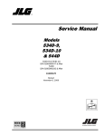
MX-1260
Multi Zone Amplifier
OWNER’S MANUAL
ZONE
TO PREVENT FIRE OR SHOCK HAZARD, DO NOT USE THIS PLUG WITH AN EXTENSION CORD,
RECEPTACLE OR OTHER OUTLET UNLESS THE BLADES CAN BE FULLY INSERTED TO PREVENT
BLADE EXPOSURE.
TO PREVENT FIRE OR SHOCK HAZARD, DO NOT EXPOSE THIS APPLIANCE TO RAIN OR MOISTURE.
TO PREVENT ELECTRICAL SHOCK, MATCH WIDE BLADE PLUG TO WIDE SLOT, FULLY INSERT.
This Lighting flash with arrowhead
Symbol, within an equilateral triangle,
Is intended to alert the use to the
Presence of un-insulated dangerous
Voltage within the products enclosure
That may be of sufficient magnitude
To constitute a risk of electric shock
To persons.
Warning: To reduce the risk of
Electric shock, do not remove
Cover (or back) no user
Servicing to qualified service
Personnel.
The exclamation point within the
Equilateral triangle is intended to
Alert the user to the presence of
Important operating and
Maintenance (servicing)
Instructions in the literature
Accompanying suppliance.
Read these instructions.
Keep these instructions.
Read all warnings.
Follow all Instruction.
Do not use this apparatus near water.
Clean only with dry cloth.
Do not block any ventilation openings. Install in accordance with the manufacturers instructions.
Do not install near heat sources such as radiators, heat registers, stoves, or other apparatus
( Including amplifiers) that Produce heat.
9. Do not defeat the safety purpose of the polarized or grounding type plug. A polarized plug has two
Blades with one wider than the other. A grounding type plug has two blades and a third grounding
Prong. If the provided plugs does not fit Into your outlet, consult an electrician for replacement of
The obsolete outlet.
10. Protect the power cord from being walked on or pinched particularly at the plugs, convenience
Receptacles, and at the point where they exit form the appliance.
11. Only use attachments or accessories specified by the manufacturer.
12. Unplug the apparatus during lightning storms or when unused for long periods of time.
13. Refer all servicing to qualified personnel. Servicing is required when the apparatus has been
Damaged in anyway, such as power supply cord or plug is damaged, liquid has been spilled or
Objects have fallen into the apparatus, the apparatus has been exposed to rain or moisture, does
Not operate normally, or has been dropped.
1.
2.
3
4
5.
6.
7.
8.
This appliance shall not be exposed to dripping or splashing water and no object filled with liquids
Such as vases shall be placed on apparatus.
775 Columbia St.Brea,CA 92821 562-697-2600 www.OSDAudio.com
2
General Information and Features
Speaker Phasing
Front Panel
To obtain proper phasing and correct bass response, it is
necessary for all channels be in correct phase. The correct
phasing occurs when speakers move in and out in unison
(in phase) on mono audio. Speakers connected in phase
ensure proper imaging while an out-of-phase connection
causes indistinct imaging. Identify the positive (+) and
negative (-) polarity on the speaker cable being used and
the corresponding connections on the speakers. Make
sure the positive terminal of the speaker is connected to
the positive terminal of the amplifier. Do the same with the
negative and then follow the same procedure with all
channels.
Power Switch: This is used to turn the unit on or off.
LED Indicators: There is one LED indicator for the power
and each of the six zones. When first turning the power on,
the power LED will come on red and then switch to blue to
indicate the amplifier is in a ready mode. If there is no
audio active to any of the inputs, after approximately 5
minutes the power light will turn red to indicate it is in sleep
mode. Zone LED lights will come on blue as each zone
senses an audio source to the zone input. In case of a fault
to a particular zone, the LED changes to RED. If the fault
remains, the corresponding LED remains red. If the short
circuit is momentary then the zone LED that changed to
red will switch to solid blue after a few seconds. Once all
zones are cleared of faults, the front LED indicators will
turn blue as long as they are active. If no audio source in
present the lights will turn off to indicate the zones are in
sleep mode.
Rear Panel
BUS 1 and 2 Inputs: There are “right” and “left” RCA style
connections labeled as “1” & “2”. These inputs are used for
sending a single audio source (i.e. CD player, tuner, MP3,
etc.) to more than one zone. For using this feature
correctly, see “Amplifier Connection” later in this manual.
BUS 1 & 2 Outputs: There are “right” and “left” RCA style
connectors labeled as “1” & “2”. These outputs are used to
loop the audio source that is connected to the “BUS
INPUTS” out to a second MX1260.
Individual Zone Line Inputs: These RCA style input
connections are the audio inputs for each individual
channel of the amplifier. These inputs are to have audio
sources dedicated to a single channel or zone on the
amplifier. We suggest using a good quality RCA patch
cable for best performance. The RCA inputs are labeled
“Left” and “Right”.
Mode Switch: This is used to switch each individual zone
between stereo or bridged.
BUS/LINE IN Switch: This is used to indicate which input
the individual channel or zone will receive audio source
from.
Sensitivity Adjustment: There is an adjustment for the
different
voltage
inputs
with
each
source
(75mVrms-3Vrms). Set the control so that the speakers are
not distorting.
Speaker Terminals: These Phoenix type terminal
connectors are used to connect the speaker to each zone.
3-Conductor AC Cord Receptacle: A standard male
receptacle that fits a 3-conductor power cord.
775 Columbia St.Brea,CA 92821 562-697-2600 www.OSDAudio.com
Amplifier Connection
Always turn off the power of your amplifier, processor preamp, and all input/playback units before any
connections are made.
Before turning your amplifier and preamp back on, make
sure your volume is turned all the way down.
Remember the cooling issues mentioned earlier in this
manual. Improper airflow will reduce the life of the
amplifier.
When deciding on the final location, keep in mind that there
needs to be adequate space behind the amp to fit the
speaker cables and patch cables.
Stereo Connection: Use a good quality RCA type patch
cord. Connect the right and left output from the processor
to the right and left input jacks on the back of the amplifier.
Repeat this for each channel and/or zone.
The “Mode” switch should be in the “Stereo” position.
Connect the speaker cable coming from each pair of
speakers to the “Speaker Input” connector on the back of
the amplifier. This connector is removable to make
connection easier. When connecting the cable to the
connector, check for any wire strands that might be sticking
out of the connection terminal that could cause a short.
When connecting the speaker cable, make sure the
speaker and amplifier are in “phase” (positive (+) and
negative (-) are matched properly). See the above section
on “Speaker Phasing”.
These amplifiers are stable down to 4 ohms. The
impedance with the connected speakers should not be
lower than 4 ohms.
Bridged Connection: The bridging mode is meant for a
single speaker within a high powered application such as a
home theater. In the bridged mode the speakers should be
8 ohm minimum.
Make sure the amplifier power is OFF before making
connections.
3
MX 1260
Connect the right or left output from the audio source to the
right or left input of the zone you are bridging. Repeat this
for each zone you want in bridged mode.
the return. This unit should not be shipped back to
OSD Audio without the RA#.
DO NOT attempt to open or dismantle
this amplifier. THIS WILL VOID THE
WARRANTY!
The “BR/ST” switch should be in the bridged (BR) position.
Make sure the switch is in this mode only on the zones you
want bridged.
Connect the speaker cables coming from one speaker to
the “speaker input” connector on the back of the amplifier.
For bridging, one speaker will connect to one connector.
Make sure to follow the labeling on the back of the amp
where the speaker input connector is labeled for the
bridged zone. The speaker input connector is removable
to make connection easier. When connecting the cable to
the connector, check for any wire strands that might be
sticking out of the connection terminal that could cause a
short.
SYMPTOM
POSSIBLE CAUSE AND
TEST PROCEDURE
Very little or no sound
on some or all channels.
1. Check the SEN/ ADJ knob that it is not
turned down.
2. Check input switch is in correct position
settings.
3. Audio cable to the input is bad. Connect
the nonworking channel to a cable known to
be good.
4. Bridging switch is in the wrong position.
BUS 1 & 2 Connection: The BUS inputs are used to input
audio sources such as a preamp, CD, tuner, and MP3
player over multiple zones. For example, you could have a
CD player on BUS 1 that goes to zones 1 and 2 and an
MP3 player on BUS 2 going to zones 3 and 4. The other
two zones could have independent input sources. When
designing a single-source, multiple-zone system, this
mode is perfect. Use a good quality RCA type patch cord.
Connect the right and left outputs from the preamp to the
right and left input connectors on the back of the amplifier.
Repeat this for each channel and or zone. Then, with the
zones on which you want to access one of the BUS
sources, put the input switch into the appropriate setting (1
or 2) position. Proceed to connect the speaker cable to
the amplifier as per the instructions in the “Stereo
Connection” section of this manual.
No sound on one
channel pair and zone
LED is red.
2. Disconnect the speaker wire at both ends.
Separate the two conductors at both ends
and test with a meter for a short circuit. If
there is no short, connect the two conductors
at one end and test for continuity.
Hum from all the
speakers.
1. Hum can be caused due to a ground
Sound is distorted on
one or more channels at
normal volume.
1. Check the setting on the SEN/ADJ knob.
You may need to turn down controls.
General Maintenance and Service
The front panel is finished with a high-grade anodizing
process to ensure that it maintains a flawless appearance.
Occasionally, you should wipe off any dust build up with a
damp, soft cloth.
Bass is weak and stereo
sound is “phasey”.
DO NOT use any kind of cleaning solution or cleanser on
these units.
If for some reason the amplifier needs to be repaired,
please contact us immediately. We will issue a Return
Authorization Number (RA#) as well as a UPS call tag for
775 Columbia St.Brea,CA 92821 562-697-2600 www.OSDAudio.com
1. Check that connections are secure and that
there are no loose strands of wire crossing
from positive to negative terminals at the
4
components (especially those connected to
antenna or cable TV feeds).
2. Check for faulty cables, faulty source
signals, an ungrounded phono system, cable
feed, and/or a defective component.
3. Reverse the AC plug of the components
with non-polarized plugs.
4. Test the AC receptacle using a ground
tester.
two adjacent channels are connected
normally but the bridging switch is set to the
bridged position, the two speakers will be out
of phase.
2. The speakers may be wired out of phase.
Recheck polarity and reverse the connections
on the back of one speaker if necessary.
4
MX1260 Multi Zone Amplifier
Conforms to
UL Std 6500
Certified to
CAN/CSA Std
C22.2 No. 1
Tested to Comply
with FCC Standards
HOME OR OFFICE
Limited Warranty
cover costs of transportation to OSD Audio or damage in transmit.The
OSD Audio warrants its audio products against defects in material
customer should return his defective product,freight prepaid and insured,to
and workmanship for a limited period of time.For a period of two years from
OSD Audio only after receiving a Return Authorization.
date of original purchase,we will repair or replace the product,at our option,
without charge for parts and labor.Customer must pay all parts and labor changes
This warranty will become void if the serial number identification has been
after the limited warranty period expiries.The limited warranty period
wholly or partially removed,altered or erased.Repair or replacement under
for factory refurbished products expires ninety days from date of original purchase.
the terms of this warranty does not extend the terms of this warranty.Should
a product prove to be defective in workmanship or material,the consumer's
This limited warranty applies only to purchases from authorized OSD Audio
sole remedies will be repair or replacement as provided under the terms
electronics retailers.This limited warranty is extended only to the original
of this warranty.Under no circumstance shall OSD Audio be liable for
purchaser and is valid only to consumers in the United States.
loss or damage,direct,consequential or incidental,arising out of the use of
or inability to use the product.There are no express warranties other than
Consumers are required to provide a copy of the original sales invoice from
described above
an authorized OSD Audio dealer when making a claim against this limited
warranty.this limited warranty only covers failures due to defects in materials
Technical Support
or workmanship that occur during normal use.It does not cover failures
If any part of this product is damaged or missing,please call your dealer or
resulting from accident,misuse,abuse,neglect,mishandling,misapplication,
OSD Audio directly at toll free 1.888.779.4968 or locally 562.697.2600.
alteration,faulty installation,modification,service by anyone other than
OSD Audio or damage that is attributable to Acts of God.It does not
775 Columbia St.Brea,CA 92821 562-697-2600 www.OSDAudio.com
5