1
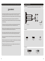
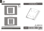
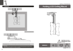
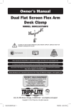
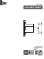
INSTALLATION MANUAL
Full Motion LED, LCD TV Wall Mount
CAUTION: DO NOT EXCEED RATED
LISTED WEIGHT CAPACITY. SERIOUS
INJURY OR PROPERTY DAMAGE MAY
OCCUR!
LCD-101
75x75/100x100
27"
MAX
15kg
(33lbs)
RATED
ISSUED: MAY. 2013
NOTE: Read the entire instruction manual before you start installation and assembly.
Component Checklist
IMPORTANT: Ensure that you have received all parts according to the component checklist prior to installation.
If any parts are missing or faulty, telephone your local distributor for a replacement.
WARNING
• Do not begin the installation until you have read and understood the instructions
and warnings contained in this installation sheet. If you have any question
regarding any of the instructions or warnings, please contact your local distributor.
• This mounting bracket was designed to be installed and utilised ONLY as
specified in this manual. Improper installation of this product may cause damage
or serious injury.
• This product should only be installed by someone with good mechanical ability
who has basic building experience and fully understands this manual.
• Make sure that the supporting surface will safely support the combined weight of
the equipment and all attached hardware and components.
wall mount (x1)
A
Allen key (x1)
B
Package M
• If mounting to wood wall studs, make sure that mounting screws are anchored
into the center of the studs. The use of a stud finder is highly recommended.
• Always use an assistant or mechanical lifting equipment to safely lift and position
the equipment.
• Tighten screws firmly, but do not over tighten. Over tightening can cause damage
to the items, This greatly reduces their holding power.
M4x14 (x4)
M-A
M5x14 (x4)
M-B
D5 washer (x4)
M-C
• This product is intended for indoor use only. Using this product outdoors could
lead to product failure and personal injury.
Package W
ST5.5x50 (x2)
W-A
1
concrete anchor (x2)
W-B
2
1b. Solid Brick and Concrete Mounting
1a. Wood Stud Wall Mounting
50mm
(2")
( 2")
55mm
((2.2")
2.2")
ø 4mm
(ø 5/32”)
1
ø 8mm
(ø 5/16")
2
1
Find and mark the
exact location of
mounting holes
Mark the
exact location of
mounting holes
2
3
Drill pilot holes
Drill pilot holes
√
W-A
X
X
√
W-B
X
X
W-A
Screw the wall
mount onto the
wall
Screw the wall
mount onto the
wall
WARNING
• Make sure that mounting screws are anchored into the center of the studs. The use of a stud
finder is highly recommended.
• Installers are responsible to provide hardware for other types of mounting situations.
• Installers must verify that the supporting surface will safely support the combined weight of the
equipment and all attached hardware and components.
3
WARNING
Installers must verify that the supporting surface will safely support the combined weight of the
equipment and all attached hardware and components.
4
2. Attach the Display to the VESA Plate
M-C
M-A/M-B
Tension is pre-set at the factory. If too tight or too
loose, you may adjust the tension by loosening or
tightening the head and arm adjustment bolts.
B
180°
180°
180°
+70°
-70°
Lift the display and match the holes on your display with the holes on the mount. Secure your display to
the mount by tightening screws.
Tighten all screws but do not over tighten.
3. Adjustment
Adjust to the desired location or tilt.
Maintenance
• Check that the bracket is secure and safe to use at regular intervals(at least every three months).
• Please contact your dealer if you have any questions.
B
Tighten the adjustment screw by using an Allen Key provided to fix the tilting angle.
5
6