1
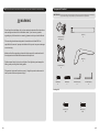
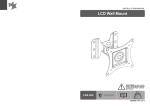
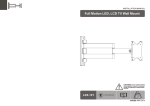
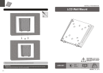
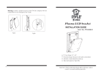
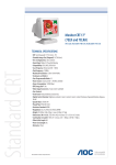
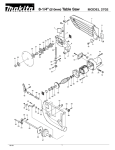
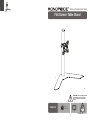
INSTALLATION INSTRUCTIONS
Flat Screen Table Stand
CAUTION: DO NOT EXCEED MAXIMUM
LISTED WEIGHT CAPACITY. SERIOUS
INJURY OR PROPERTY DAMAGE MAY
OCCUR!
PID 5970
75x75
100x100
23"
MAX
15kg
(33lbs)
MAX
ISSUED: NOV. 2012
NOTE: Read the entire instruction manual before you start installation and assembly.
Component Checklist
IMPORTANT: Ensure that you have received all parts according to the component checklist prior to installing. If
any parts are missing or faulty, telephone your local distributor for a replacement.
WARNING
• Do not begin the installation until you have read and understood the instructions
and warnings contained in this installation sheet. If you have any question
regarding any of the instruction or warning, please contact your local distributor.
• This mounting bracket was designed to be installed and utilized ONLY as
specified in this manual. Improper installation of this product may cause damage
or serious injury.
pole (x1)
C
adapter bracket
assembly (x1)
A
• Make sure that the supporting surface will safely support the combined load of
the equipment and all attached hardware and components.
• Tighten screws firmly, but do not over tighten. Over tightening can damage the
items, greatly reducing their holding power.
base (x1)
D
VESA plate (x1)
B
• This product is intended for indoor use only. Using this product outdoors could
lead to product failure and personal injury.
M10x20 (x1)
E
M5x20 (x2)
F
3mm Allen key (x1)
G
4mm Allen key (x1)
H
Package M
M4x14 (x4)
M-A
1
M5x14 (x4)
M-B
2
2. Install the VESA Plate
1. Assemble the Table Stand
TV
TV
TV
A
Attach the pole to the
base using the screw.
C
Top of display
D
M-A/M-B
Screw the VESA plate onto the display.
Tighten all screws but do not over tighten.
E
3. Install the Display
• Remove the plastic cover.
• Slide the adapter bracket assembly to a
desired position.Tighten the assembly firmly
using 4mm Allen key.
• Re-attach the plastic cover.
H
Lift your display carefully and hook the
VESA plate onto the mounted head.
3
4
4. Adjustment
Depending on the weight of the display,it may be
necessary to make adjustments to the Ball Joint
Mechanism.
G
60°
+30°
F
360°
-30°
Insert two screws into
mounting holes.
H
Adjust to desired location or tilt.
Tighten all screws using 4mm Allen key.
5
Maintenance
• Check that the bracket is secure and safe to use at regular intervals(at least every three months).
• Please contact your dealer if you have any questions.
6