1
Contents
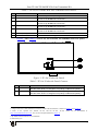
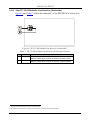
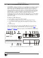
Figure 10: TP-123 Internal Polarity Switches
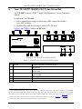
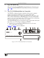
Figure 11: TP-124 XGA/Audio/Data Line Receiver (Topside)
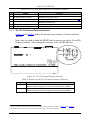
Figure 12: TP-124 XGA/Audio/Data Line Receiver (Underside)
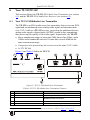
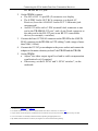
Figure 13: Connecting the XGA/Audio Line Transmitter/Receiver System
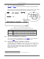
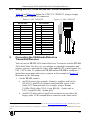
Figure 14: CAT 5 PINOUT
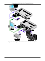
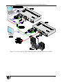
Figure 15: Connecting the XGA/Audio/Data Line Transmitter/Receiver System
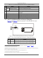
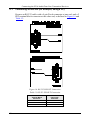
Figure 16: RS-232 PINOUT Connection
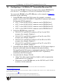
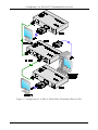
Figure 17: Configuring a 1:4 XGA to Twisted Pair Transmitter/Receiver/DA
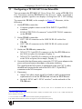
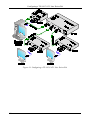
Figure 18: Configuring a TP-105 CAT 5 Line Driver/DA
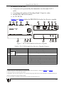
14
15
16
18
19
21
22
24
26
Tables
Table 1: TP-104, TP-104HD XGA Line Transmitter/DA Features
Table 2: TP-104 (Underside Panel) Features
Table 3: TP-105 CAT 5 Line Driver/DA Features
Table 4: TP-121 XGA/Audio Line Transmitter Features
Table 5: Features of the TP-121 Internal Polarity Switches
Table 6: TP-122 XGA/Audio Line Receiver (Topside) Features
Table 7: TP-122 XGA/Audio Line Receiver (Underside) Features
Table 8: TP-123 XGA/Audio/Data Line Transmitter Features
Table 9: Features of the TP-123 Internal Polarity Switches
Table 10: TP-124 XGA/Audio/Data Line Receiver (Topside) Features
Table 11: TP-124 XGA/Audio/Data Line Receiver (Underside) Features
Table 12: CAT 5 PINOUT
Table 13: RS-232 PINOUT Connection
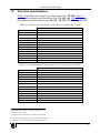
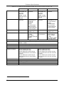
Table 14: Technical Specifications of the TP-104 and the TP-104HD
Table 15: Technical Specifications of the TP-105 and the TP-105(HD)
Table 16: Technical Specifications of the TP-121/TP-122/TP-123/TP-124
ii
7
7
8
9
10
11
12
14
14
16
16
19
22
27
27
28
KRAMER: SIMPLE CREATIVE TECHNOLOGY