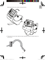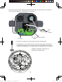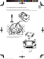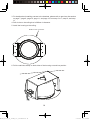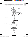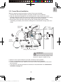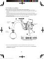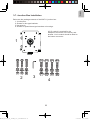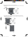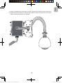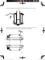
1
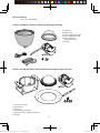
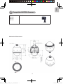
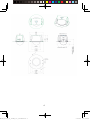
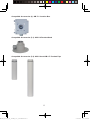
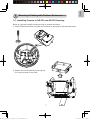
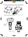
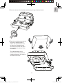
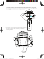
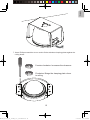
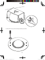
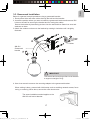
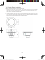
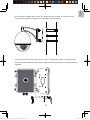
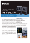
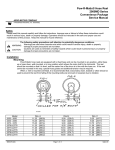
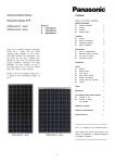
IP8152_housing_ig_VVTK_v1.0_20121206.indd 1
VIVOTEK IP8152 Mini Box Series
Outdoor Enclosure
Using
AE-251/-252 Outdoor Enclosure,
AE-201/-202 Indoor Enclosure,
AM-114 Pendant Head (outdoor),
AM-116 and AM-117 Pendant Pipes,
AM-221 Gooseneck,
AM-212 Wall-mount bracket,
AM-311 Pole Mount,
AM-411 Corner Mount,
AM-711 Junction Box.
Installation Guide
Rev. 1.0
IP Sur veillance
2013/1/10 下午 01:36:27
Revison History:
Rev. 1.0: Initial release.
AE-251 and AE-252 Outdoor Enclosure Package Contents
1. Enclosure.
2. Dome cover.
3. Power supply with cable.
4. Camera Mount bracket.
5. Dome clearance
measurement tool.
6. Screws.
AE-201 and AE-202 Indoor Recess Mount Housing Package Contents
1. Enclosure (indoor).
2. Dome cover.
3. Trim ring.
4. Camera Mount bracket.
5. Dome clearance measurement tool.
6. Screws.
IP8152_housing_ig_VVTK_v1.0_20121206.indd 2
2
2013/1/10 下午 01:36:28
English
1
Compatible VIVOTEK Cameras
AE-201
AE-202
AE-251
AE-252
IP8152
Mechanical Dimensions
IP8152_housing_ig_VVTK_v1.0_20121206.indd 3
3
2013/1/10 下午 01:36:29
IP8152_housing_ig_VVTK_v1.0_20121206.indd 4
4
2013/1/10 下午 01:36:34
English
Warning:
1. Select a suitable location where the camera is free from accidental damage, tampering,
or harsh environmental conditions.
2. Locate a place for the installation where the camera can not be intentionally or
unintentionally interfered.
3. Select a solid and flat mounting surface that can support the combined weight of the
camera and associated hardware. Vibration and temperature ranage should also be
taken into consideration.
2
Compatible Accessories
Compatible Accessories (1-1): AM-221 Gooseneck Bracket
Compatible Accessories (1-2): AM-212
Wall-mount Bracket
Compatible Accessories (2): AM-311 Pole Mount
Bracket
Compatible Accessories (3): AM-411 Corner Mount Bracket
IP8152_housing_ig_VVTK_v1.0_20121206.indd 5
5
2013/1/10 下午 01:36:36
Compatible Accessories (4): AM-711 Junction Box
Compatible Accessories (5-1): AM-114 Pendant Head
Compatible Accessories (5-2): AM-116 and AM-117 Pendant Pipe
IP8152_housing_ig_VVTK_v1.0_20121206.indd 6
6
2013/1/10 下午 01:36:37
English
3
Mounting & Cabling with Outdoor Enclosures
3-1. Installing Camera to AE-251 and AE-252 Housing
Below is a general sample procedure using an outdoor enclosure:
1. Use a Phillips screwdriver to loosen the 2 screws on the sides of the camera bracket.
2. Detach the inner bracket by loosening the
four thumb screws on the sides.
IP8152_housing_ig_VVTK_v1.0_20121206.indd 7
7
2013/1/10 下午 01:36:38
3. The IP8152 supports 4 different lens modules. If you are installing the larger lens [AL231(2.8-12mm), and AL-234(5-50mm)], you need to remove the inner bracket and install
it in the opposite direction as shown below. Tighten the hand screws from the sides.
4. Reverse the inner bracket if the larger lens (AL-231 and AL-234) are used. Secure the
inner bracket from the sides as illustrated below.
Smaller lens:
Mounted on the
outer edge of
bracket
IP8152_housing_ig_VVTK_v1.0_20121206.indd 8
16 -14 -12 -10 -8 -6 -4 -2 --
-- 15
-- 13
-- 11
-- 9
-- 7
-- 5
-- 3
16 --
-- 1
14 -12 -10 -8 -6 -4 -2 --
-- 15
-- 13
-- 11
-- 9
-- 7
-- 5
-- 3
-- 1
Larger lens:
Mounted inside the bracket
8
2013/1/10 下午 01:36:41
English
5. Secure camera to the bracket assembly by driving a flathead screw.
6. Bend the included measurement
tool into a rectangular arch.
Attach the measurement tool
to the top of camera lens to
ensure your lens will not get in
the way when the dome cover
is installed.
The vertical length of the
measurement tool equals the
clearance between the bracket
and the dome cover.
IP8152_housing_ig_VVTK_v1.0_20121206.indd 9
9
2013/1/10 下午 01:36:42
You should also swing the measurement tool and the camera back and forth to make
sure there is enough clearance at different shooting angles. You can make adjustments
by changing the camera's position along the bracket.
.
7.Secure the camera to the large base bracket by fastening
the 4 thumb screws while you orient your camera's
shooting direction.
IP8152_housing_ig_VVTK_v1.0_20121206.indd 10
10
2013/1/10 下午 01:36:43
English
Make adjustments to the camera's shooting direction.
8. Feed power lines and other cables through a gooseneck bracket, a pendant head, or a
pendant pipe.
IP8152_housing_ig_VVTK_v1.0_20121206.indd 11
11
2013/1/10 下午 01:36:44
9. Insert and connect power cables and the Ethernet cable as shown below. The IP8152
can only be powered by a PoE Ethernet connection.
PoE
for
camera
DC 12V input for onboard
heater
Unused
10. Install the camera into the housing by driving 2 M6 screws.
11. Depending on your choice with the mounting type using a gooseneck
or other accessories, refer to the instructions in the following sections to
complete the installation. The dome cover is installed after you complete
IP8152_housing_ig_VVTK_v1.0_20121206.indd 12
hardware installation and acquire a
satisfactory imaging result.
12
2013/1/10 下午 01:36:45
English
3-2. Installing AE-201 and AE-202 Housing
Below is a general sample procedure using an outdoor enclosure:
1. Use a Phillips screwdriver to loosen the 2 screws on the sides of the camera bracket.
2. Detach the inner bracket by loosening the
four thumb screws on the sides.
IP8152_housing_ig_VVTK_v1.0_20121206.indd 13
13
2013/1/10 下午 01:36:47
3. For details about installing camera to the brackets, please refer to previous discussions
on page 7, page 9, page 10, page 11, and page 12; from step 3 to 7, step 10, and step
11.
4. Drill a hole on the ceiling that is 290mm in diameter.
5. Install the housing to the ceiling.
Ø 290 mm hole in diameter
6. Pull the stainless clamp on both sides of the housing out and into position.
IP8152_housing_ig_VVTK_v1.0_20121206.indd 14
14
2013/1/10 下午 01:36:47
English
7. Use a Phillips screwdriver to turn and to fit the stainless clamping plates against the
ceiling board.
IP8152_housing_ig_VVTK_v1.0_20121206.indd 15
Counter-clockwise: Increases the clearance
Clockwise: Brings the clamping plate closer
to ceiling
15
2013/1/10 下午 01:36:47
8. Install the trim ring to the housing by fastening 4 screws.
IP8152_housing_ig_VVTK_v1.0_20121206.indd 16
16
2013/1/10 下午 01:36:48
Below is a general, sample procedure using a gooseneck bracket:
1. Route power lines and other cables through the wall and the bracket.
2. Locate the position where you want to install the gooseneck bracket and camera. Drill
holes on the wall for securing the bracket and for routing the cables.
Secure the bracket by hammering anchors into the wall and then fasten hex nuts and
washers on them.
3. Attach the outdoor enclosure to the bracket by rotating it clockwise until it is tightly
fastened.
English
3-3. Gooseneck Installation
1
2
Cables
AM-221
Gooseneck
bracket
4
3
IMPORTANT:
The screws and mounting surface must be able
to support a weight of 6 kg.
4. Use a hex wrench to secure the mounting adapter to the gooseneck bracket.
When cabling is done, proceed with initial setup such as enabling network access, focus
tuning, or zooming. When done, secure the outer dome cover.
The same installation method applies to the
AM-212 wall-mount bracket.
IP8152_housing_ig_VVTK_v1.0_20121206.indd 17
17
2013/1/10 下午 01:36:48
3-4. Pendant Mount Installation
Below is a sample procedure using a Pendant pipe:
1. Determine a hard surface ceiling location, and use the mounting holes on the pendant
head itself for marking where holes will be drilled to secure the pendant head. Drill
holes 10mm in diameter and 60mm deep.
2. Locate the position where you want to install the pendant pipe and camera. Drill holes
on the ceiling for securing the pendant head. Secure the pendant head by hammering
anchors into the ceiling and then fasten screws through it.
IP8152_housing_ig_VVTK_v1.0_20121206.indd 18
18
2013/1/10 下午 01:36:48
English
3. Route power lines and other cables through the side opening and a 1-inch conduit
(user-supplied), and through the pendant pipe.
4. Secure pendant pipe to the pendant head by rotating it clockwise until it is tightly
fastened.
Cables
3
Pendant Head
5
4
Pendant Pipe
7
Outdoor Enclosure
IP8152_housing_ig_VVTK_v1.0_20121206.indd 19
6
19
2013/1/10 下午 01:36:49
5. Secure the connection using the included hex wrench.
6. Attach the outdoor enclosure to the pendant pipe by rotating it clockwise until it is tightly
fastened.
7. Secure the connection using the included hex wrench.
When cabling is done, proceed with initial setup such as enabling network access, focus
tuning, or zooming. When done, secure the outer dome cover.
IP8152_housing_ig_VVTK_v1.0_20121206.indd 20
20
2013/1/10 下午 01:36:49
English
3-5. Corner Mount Installation
Below is a general, sample procedure using a Corner mount bracket:
1. Combine the two brackets together using the included nuts and washers.
2. Align the assembled brackets with the desired position. Align screw holes on the
brackets against the wall. Drill holes on the wall for securing the bracket and for routing
the cables. Hammer anchors into the wall. Wall anchors are user-supplied.
3. Route power lines and other cables through the included cable gland, conduits
(separately purchased), and install the cable gland to the brackets' through hole in the
center.
Gooseneck
bracket
5
1
Corner Mount
Bracket
Outdoor
Enclosure
2
6
3
4
Cable gland and 3/4" conduits
IMPORTANT:
The screws and mounting surface must
be able to support a weight of 6 kg.
4. Secure corner mount brackets to the wall. Screws are user-supplied.
5. Fill the unused holes on the bracket with the included silicone stoppers.
6. Use the included hex bolts, washers, and nuts to secure the gooseneck to the corner
mount bracket.
7. The rest of the mounting procedure is identical to those described in the Gooseneck
installation on page 10.
IP8152_housing_ig_VVTK_v1.0_20121206.indd 21
21
2013/1/10 下午 01:36:49
3-6. Pole Mount Installation
Below is a general, sample procedure using a Pole mount bracket:
1. Route power lines and other cables through the included cable gland, pass them
through conduits (separately purchased), and install the cable gland to the pole mount
bracket.
2. Locate the position where you want to install the pole mount bracket and camera.
Unwrap the stainless belts, feed them through the openings on the sides of the bracket,
and then strap them around the pole. Use a pincer and flathead screwdriver to fasten
the bracket to the pole.
3. Fill the unused screw holes using the included silicone stoppers.
4
Gooseneck
bracket
2
Outdoor
Enclosure
Pole mount
bracket
3
1
Cable gland and 3/4" conduits
4. Secure the gooseneck bracket using the included hex bolts, washers, and nuts.
The rest of the mounting procedure is identical to those described in the Gooseneck
installation on page 10.
IP8152_housing_ig_VVTK_v1.0_20121206.indd 22
22
2013/1/10 下午 01:36:50
English
3-7. Junciton Box Installation
Below are the package contents of the AM-711 junction box:
1. Junction box.
2. Screws for box type brackets.
3. Hex wrench.
4. Screws for speed dome type brackets or housings.
A 3/4" conduit is required for the
waterproof connector in the center, and
another 1-inch conduit should be fitted to
the bottom connector.
1
2
IP8152_housing_ig_VVTK_v1.0_20121206.indd 23
3
4
23
2013/1/10 下午 01:36:50
Below is a general, sample procedure using a junction box:
1. Use the included hex wrench to remove the socket head cap screws, and then open the
front panel.
2. Use a Phillips screwdriver to loosen and remove the middle plate in the junction box.
Feed cables and install accessories, such as power adaptors, through the box and the
waterproof connectors on the box.
IP8152_housing_ig_VVTK_v1.0_20121206.indd 24
24
2013/1/10 下午 01:36:51
IP8152_housing_ig_VVTK_v1.0_20121206.indd 25
English
3. Use the included hex head bolts to secure a gooseneck bracket to the junction box.
4. cables should have been connected and routed through the waterproof connectors.
Cable conduits should also be installed.
25
2013/1/10 下午 01:36:51
5. Use the included hex wrench to fasten the socket head screws for the front door.
6. Use the 4 mounting holes on the back of the junction box to attach a pole mount or a
corner mount bracket to the box. See previous discussions for details.
IP8152_housing_ig_VVTK_v1.0_20121206.indd 26
26
2013/1/10 下午 01:36:52
English
7. You should then attach the junction box, along with the camera, to a pole-mount or
corner-mount position. A pole-mount installation is shown below.
You may also mount the junction box to a wall. The mounting holes on the right hand
side is accessible when the front door is opened, and the anchors and screws are usersupplied.
IP8152_housing_ig_VVTK_v1.0_20121206.indd 27
27
2013/1/10 下午 01:36:52