1
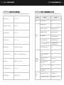
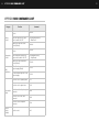
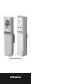
GSM POWER SOCKET
USER MANUAL
2
CONTENTS
CONTENTS
Thank you for purchasing the GSM power socket.
The GSM power socket is a remotely controlled power socket using any 2G Pay
as you Go SIM (Not Three as they are purely a 3G Network). The power supply
output of the socket can be turned on or off remotely by SMS (Short Message
System) command or locally controlled by its function buttons. It is an intelligent
power socket that can be controlled anytime and anywhere by a mobile phone.
The GSM power socket is designed for any electrical appliance for business or
domestic use up to 13 Amp for the UK version and 16 Amp for the Schuko
version with a power consumption of up to 3 Kw. It can be used for any type of
device and IEC13 conversion cables for PCs and Servers are available.
When used with the plug in temperature sensor, the GSM power socket can
switch power on or off according to the environment temperature. It is suitable
for power control of heating or cooling equipment by keeping the environmental
temperature within a pre-set range or at a fixed temperature value.
All services and functions need to be supported by the GSM network and a
SIM card.
This instruction manual provides both a quick start set up and also more
advanced settings if the user wishes to programme the GSM power socket by
temperature or time/date.
Important Information ………………………………………………………………05
Safety Recommendations …………………………………………………………06
Disclaimer Notice …………………………………………………………………07
CHAPTER 1 - FEATURES AND ACCESSORIES
1.1 Main Functions ………………………………………………………………09
1.2 List of Contents ………………………………………………………………09
1.3 Schematic Drawings…………………………………………………………10
1.4 Temperature Sensor Drawing ………………………………………………11
1.5 LED Light Indicators (KEY) …………………………………………………11
CHAPTER 2 - QUICK START
2.1 Installing the SIM Card and Temperature Sensor …………………………13
2.2 Turning the Socket On/Off …………………………………………………13
2.3 User Authorisation Levels……………………………………………………14
2.4 Setting the Master Number …………………………………………………14
2.5 Setting the Date/Time (GMT) ………………………………………………15
2.6 Controlling the Output / Power ……………………………………………15
2.7 Notification of Power Supply Loss …………………………………………16
CHAPTER 3 - ADVANCED SETTINGS
3.1 Defining the Users …………………………………………………………18
3.1.1 Changing the Master Number ……………………………………18
3.1.2 Adding an Additional User / Number ……………………………18
3.1.3 Checking Additional User’s / Number’s …………………………18
3.1.4 Deleting an Additional User / Number ……………………………18
3.2 Controlling the Output by Calling …………………………………………19
3.3 Controlling the Output by a Time Delay ……………………………………19
3.4 Controlling the Output by Time / Date ……………………………………20
3.4.1 Turning ON the Control Output by Time / Date Function ………20
3.4.2 Setting the Time / Date to Control the Output ……………………20
3.4.3 Turning OFF the Control Output by Time / Date Function ………21
3
4
CONTENTS CONTINUED
CONTENTS
3.5
3.6
3.7
3.8
Controlling the Output by Temperature ……………………………………21
3.5.1 Turning ON the Control Output by Temperature Function ………21
3.5.2 Setting the Temperature Range to Control the Output …………22
3.5.3 Turning OFF the Control Output by Temperature Function………23
SMS Notification Upon the Socket Output Changing ……………………23
Checking the Socket Status…………………………………………………24
Resetting the Socket…………………………………………………………25
CHAPTER 4 - MAINTENANCE ………………………………………………26
CHAPTER 5 - GENERAL TROUBLESHOOTING ………………………27
CHAPTER 6 - MAIN TECHNICAL …………………………………………28
APPENDIX SMS COMMANDS LIST ………………………………………29
INFORMATION
IMPORTANT INFORMATION
PLEASE READ THIS IMPORTANT INFORMATION
• The SIM card mobile number is referred to as the GSM socket number
in this manual
• Before using this socket, check if mobile phones can be used in the area
• We recommend before choosing your network provider you check the
signal strength of where the socket is to be located and make sure it
is strong
• Be sure to keep the password and mobile number safe, we
recommend you change the pre-set password of 1234 and do not
disclose this information to anyone other than the authorised users in
order to ensure there is no misuse
• A PAYG SIM Card is required for use in this product, please make sure
the that SIM Card has credit at all times for this product to be effective
• Master user’s SMS command format: #code#content#
• Additional user’s/number’s command format:
#code#content#password#
• The password must be a four-digit number
• The original password is 1234
• The maximum digits that are allowed for the phone number is sixteen
• The GSM power socket will reply to the user after it receives an SMS
command
• The # symbol must not be ignored when typing an SMS command
• Do not include any spaces within the commands
NB: Although we recommend PAYG SIMS to be used with the GSM power
socket, contract SIMS can also be used however PAYG SIM’s are
much more cost effective as the GSM power socket can only send
SMS messages.
5
6
SAFETY RECOMMENDATIONS
DISCLAIMER NOTICE
SAFETY RECOMMENDATIONS
DISCLAIMER NOTICE
• This socket is designed for business or domestic use for any appliance not
exceeding 13 Amps for UK version and 16 Amps for Schuko version or 3 Kw
output
• We operate a policy of continuous development and therefore we reserve the
right to make changes and improvements to the design, functionally or any
part of the socket as described in this document without prior notice
• This socket was designed for indoor use; do not use it in a wet / chemically
aggressive / dusty environment
• For the latest information please contact your supplier
• Do not open up the GSM power socket, there are no serviceable parts inside
• We cannot be held responsible in any way should this product be used other
than for the intended purpose
• This socket uses wireless signal transmissions, please keep it away from
electronic equipment that may be likely to cause interference
• Keep the socket and its accessories out of reach of children
• Should the GSM socket not function as detailed in this instruction book,
please contact your supplier for technical support
• If the GSM power socket is faulty or the issue cannot be resolved after
technical support please contact your supplier
• We accept no responsibility for any loss of income or any damages whether
consequential or indirectly and however caused due to the use of this socket
7
8
CHAPTER 1 FEATURES AND ACCESSORIES
CHAPTER 1 FEATURES AND ACCESSORIES
CHAPTER 1 FEATURES AND ACCESSORIES
1.1 MAIN FUNCTIONS
1.1
MAIN FUNCTIONALITY
1.2
LIST OF CONTENTS
1.3
SOCKET INSTRUCTIONS
1.4
TEMPERATURE SENSOR INSTRUCTION
•
•
•
•
•
•
•
1.5
LIGHT INDICATORS
•
•
•
•
•
The GSM power socket uses a PAYG SIM card
The GSM power socket is operated remotely by SMS command
Output Max: 13 Amp for UK version and 16 Amp for Schuko version
M button: To manually control output power (on/off)
Time delayed control of output power (on/off)
Auto operation by pre-set time/times/days
The GSM power socket is supplied with a plug in external temperature
sensor
Automatic operation by pre-set upper/lower temperature thresholds
(on/off)
Receive temperature reading in the location via a simple SMS command
Supports 1 master and 4 additional numbers/users
Automatic time/date synchronization
Receive SMS message on external power failure
1.2 LIST OF CONTENTS
• 1 x GSM power socket
• 1 x External plug in temperature sensor
• 1 x User manual
9
10
CHAPTER 1 FEATURES AND ACCESSORIES
1.3 SCHEMATIC DRAWINGS
CHAPTER 1 FEATURES AND ACCESSORIES
1.4 TEMPERATURE SENSOR DRAWING
Figure 2: Temperature Sensor Drawing
1.5 LED LIGHT INDICATORS (KEY)
Indicator
Action
Status
No Light
No Mains Power Available
Constant Light
Mains Power Available
No Light
No GSM Signal / Socket Switched
Off
Flashing Light
Searching GSM Network / Sending
an SMS
No Light
Socket Power to Connected Device
OFF
Constant
Socket Power to Connected Device
ON
Power Light
(Green LED)
GSM (Blue)
Light
Output Light
(Red LED)
Figure 1: GSM socket instructions
11
12
CHAPTER 2 QUICK START
CHAPTER 2 QUICK START
CHAPTER 2 QUICK START
2.1 INSTALLING THE SIM CARD AND TEMPERATURE SENSOR
1. The power switch should be in the “OFF” position (See 7 on Figure 1)
(please make sure the power socket is off before inserting the SIM Card)
2.1
INSTALL THE SIM CARD AND TEMPERATURE SENSOR
2.2
TURNING THE SOCKET ON/OFF
2.3
USER AUTHORISATION LEVEL
2.4
SETTING THE MASTER NUMBER
2.5
SETTING THE DATE/TIME (GMT)
2.6
CONTROLLING THE OUTPUT/POWER
2.7
NOTIFICATION OF POWER SUPPLY LOSS
2. Open the socket’s SIM cover, you will see a SIM card holder (See 8 on
Figure 1)
3. Slide the metallic cover of the holder in the direction of “OPEN”, then lift
the metallic cover up and towards you
4. Put the SIM card with the gold contacts face down and the slight corner
cut out of the SIM at the bottom left
5. Slide back the metallic cover in the direction of “LOCK” and make sure
the SIM card locks into place
6. The SIM card will be fixed in the holder
7. Insert the temperature sensor into the I/O port (see 3 Figure 1)
2.2 TURNING THE SOCKET ON/OFF
1. Turn the power switch to “ON” position (see 7 on Figure 1)
2. Plug the GSM power socket into a UK 13 Amp / Schuko socket
3. The “Green” power light will illuminate and the “Blue” GSM light will flash
for about 20 seconds before staying on constantly to confirm GSM signal
is available (PLEASE MAKE SURE THE SIGNAL IN THE AREA IS GOOD)
4. The socket is now ready to be programmed for remote use
Note: The unit can be turned off by the switch (see 7 Figure 1) when not required for
a period of time.
13
14
CHAPTER 2 QUICK START
2.3 USER AUTHORISATION LEVEL
All settings can be adjusted via SMS command’s. The GSM power socket
has two levels of control.
Master User:
Only the master user has authorisation to use all the features of the GSM
power socket.
Only one master number can be programmed per socket. The master
number can be changed to another number by sending an SMS command.
Additional users:
Four additional users have authorisation to use two commands to switch
on or cut off the socket output.
The other mobile phone users have no authorisation to use the GSM power
socket.
If there are any changes made to the GSM power socket the master user
always gets the notifications.
CHAPTER 2 QUICK START
2.5 SETTING THE DATE/TIME (GMT)
Important note
If the power socket is being used for the first time, or it has been reset, the
master user must set the socket time according to the current time of the
SMS centre. If the time is not set the power socket will use the original preset start date / time from 00:00:00 1st June 2004.
Please send the following command to set the time: #152#
Successful SMS reply
The time of the device has been regulated automatically **********
2.6 CONTROLLING THE OUTPUT/POWER
Method 1
(Master) Please send the following command to turn the power socket
output ‘ON’: #01#
(Additional User) Please send the following command to turn the power
socket output ‘ON’: #01#password#
2.4 SETTING THE MASTER NUMBER
The user must send the following SMS to the socket from their mobile
phone, they will then become the master.
Please send the following command to add a master number: #00#
Successful SMS reply
Welcome to the GSM socket. Your password is 1234
Failed SMS reply
If a user tries to add another master user, the GSM power socket will send
an SMS stating “The master user already exists”, to change the master
number please refer to Chapter 3.1.4.
Please note unless otherwise stated SMS commands to the socket
can only be sent by the master user.
(Master) Please send the following command to turn the power socket
output ‘OFF’: #02#
(Additional User) Please send the following command to turn the power
socket output ‘OFF’: #02#password#
Successful SMS reply
The socket power output has been switched on
The socket power output has been switched off
Method 2
Press the M button (See 3 on Figure 1) on the side of the socket for ½ a
second until the output light goes on/off and then again to turn the output
back on/off
15
16
CHAPTER 2 QUICK START
2.7 NOTIFICATION OF POWER SUPPLY LOSS
External power supply lost
If the GSM power socket is disconnected from external AC power or a loss
of the AC power occurs, all functions of the socket are deactivated
including the M button and the GSM power socket will notify the master;
“Main Electricity Supply Lost” together with a temperature reading.
External power supply restored
If the power socket is reconnected with external AC power or the external
AC power is restored and the power socket is available again, the SMS
notification will be sent to the master; “Main Electricity Supply Restored”,
together with a temperature reading. When the external power supply is
resumed, the output of the GSM socket will keep the same status as that of
before the external power supply failure if the power switch of the GSM
socket is not turned off. For example, if the device connected to the GSM
power socket was ‘ON’ before the external power supply was cut off the
device will turn back ‘ON’ when power is restored. If the power supply is
switched on and off quickly the GSM power socket will send the
outstanding SMS messages.
The GSM power socket will notify the master user when there are
any external power changes.
CHAPTER 3 ADVANCED SETTINGS
CHAPTER 3 ADVANCED SETTINGS
3.1
DEFINING THE USERS
3.1.1
Changing the Master Number
3.1.2
Adding an Additional User / Number
3.1.3
Checking Additional User’s / Number’s
3.1.4
Deleting an Additional User / Number
3.2
CONTROLLING THE OUTPUT BY CALLING
3.3
CONTROLLING THE OUTPUT BY A TIME DELAY
3.4
CONTROLLING THE OUTPUT BY TIME / DATE
3.4.1
Turning ON the Control Output by Time / Date Function
3.4.2
Setting the Time / Date to Control the Output
3.4.3
Turning OFF the Control Output by Time / Date Function
3.5
CONTROLLING THE OUTPUT BY TEMPERATURE
3.5.1
Turning ON the Control Output by Temperature Function
3.5.2
Setting the Temperature Range to Control the Output
3.5.3
Turning OFF the Control Output by Temperature Function
3.6
SMS NOTIFICATION UPON THE SOCKET OUTPUT CHANGING
3.7
CHECKING THE SOCKET STATUS
3.8
RESETTING THE SOCKET
17
18
CHAPTER 3 ADVANCED SETTINGS
3.1 DEFINING THE USERS
3.1.1 CHANGING THE MASTER NUMBER
To change the master number please send the following SMS command
to the socket: #14#NewMasterNumber#
CHAPTER 3 ADVANCED SETTINGS
3.2 CONTROLLING THE OUTPUT BY CALLING
If the master user calls the GSM power socket, the socket output will be
switched on / off automatically when the user hears the ring tone in the
phone. The call will end automatically if the user doesn’t hang up the call.
By default this function is de-activated, first the function needs to be enabled.
To enable this function please send the following SMS command: #18#1#
3.1.2 ADDING AN ADDITIONAL USER / NUMBER
Up to 4 additional user’s / number’s can control this socket. Additional
users have the authority to turn the socket’s output on / off.
To add additional users the master must send the following SMS
command: #06#AdditionalNumber#
To disable this function the master user sends the following SMS
command: #18#0#
Successful SMS reply
Control the socket power output status by calling de-activated
Control the socket power output status by calling activated
To add several users at the same time the master must send the following
SMS command: #06#AdditionalNumber1#…#AdditionalNumber4#
*The number required is the additional user’s mobile number.
3.3 CONTROLLING THE OUTPUT BY A TIME DELAY
Successful SMS reply
#......# The additional number has been set successfully
The GSM power socket can be set by SMS command so there is a delay in
turning on or turning off the output of the socket
3.1.3 CHECKING ADDITIONAL USER’S / NUMBER’S
NOTE: When the ‘Delayed output function’ is applied the pre-set “timed
switching of the socket output” function will be overridden. When any
functions of the socket are over-ridden (i.e. if the socket output is delayed to
turn off after 10 minutes and then you send an SMS command to turn the
socket off after 2 minutes the ‘delayed output function’ will be cancelled.
Refer to Chapter 3.7 Check status.
To delete several additional users / numbers please send the following
SMS command to the socket:
#113#AdditionalNumber1#…#AdditionalNumber4#
This is the same if you set the power socket output to turn on at 9am and
turn off at 5pm Monday to Friday and the send an SMS to turn the power
socket off at 3pm (or by pressing the M button to turn the socket off). To
reset these functions they need to be turned on again i.e. by sending
#128#1# again (the formula does not need to be re-entered). Sending an
SMS command also cancels the ‘temperature range function’ in the same
way as the other examples.
To delete all users / additional numbers please send the following SMS
command to the socket: #113#
To delay the output switching ON after a set number of minutes the
master user sends the following SMS command: #138#1#Minutes#
Successful SMS reply
#......# Additional numbers have been deleted.
To delay the output switching OFF after a set number of minutes the
master user sends the following SMS command: #138#0#Minutes#
Failed SMS reply
#......# The additional number does not exist.
Minutes are time parameters, its range is 0-720. If the minutes are set to 0,
the function will be invalid and the current output status of the socket won’t
be changed.
3.1.4 DELETING AN ADDITIONAL USER / NUMBER
To delete an additional user / number please send the following SMS
command to the socket: #113#AdditionalNumber#
19
20
CHAPTER 3 ADVANCED SETTINGS
CHAPTER 3 ADVANCED SETTINGS
Successful SMS reply
The socket power output is cut off now, will switch on after – minutes
The socket power output is switch on now, will cut off after – minutes
‘StartTime’ and ‘EndTime’: Consists of 4 digits (hh.mm) and works on a 24
hour clock, the ‘StartTime’ and ‘EndTime’ should be in the same day, and
the ‘EndTime’ must be later than ‘StartTime’ during the period.
The socket output will switch on at the ‘StartTime’ and cut off at the
‘EndTime’.
For example: #129#1#0000#2130#, 0000 is 00:00 AM (hh.mm), 2130 is
9.30PM.
3.4 CONTROLLING THE OUTPUT BY TIME / DATE
3.4.1 TURNING ON THE CONTROL OUTPUT BY TIME / DATE
FUNCTION
Successful SMS reply
The schedule is set successfully: ‘WorkDay’, ‘StartTime’, ‘EndTime’. Timing
control the socket activated /de-activated.
The output of the GSM power socket can be set to switch on for a period.
To enable the control by date / time function the master user must send
the following SMS command: #128#1#
Successful SMS reply
Schedule control: function ON Sunday, 00:00-00:00
To disable the control by date / time function the master user must send
the following SMS command: #128#0#
3.4.2 SETTING THE TIME / DATE TO CONTROL THE OUTPUT
When the time / date has been set successfully the scheduled parameters
will be saved in the socket. These settings are saved in the GSM power
socket and will remain until the socket is reset to factory settings. If the
socket loses external power or the power switch is turned off these
parameters are still saved within the socket.
To set the time / date control parameters the master user sends following
SMS command: #129#WorkDay#StartTime#EndTime#
WorkDay: One digit, the values lie in the range of “0” to “8”. The following
table contains the descriptions of each value.
Value Corresponding Day Value Corresponding Day Value Corresponding Day
7
3.4.3 TURNING OFF THE CONTROL OUTPUT BY TIME / DATE
FUNCTION
Everyday
3
Wednesday
6
Saturday
1
Monday
4
Thursday
0
Sunday
2
Tuesday
5
Friday
8
Monday-Friday
Successful SMS reply
Timing control the socket de-activated
3.5 CONTROLLING THE OUTPUT BY TEMPERATURE
3.5.1 TURNING ON THE CONTROL OUTPUT BY TEMPERATURE
FUNCTION
The external temperature sensor must be inserted into the I/O port of the
GSM socket. The output status of the socket can then be controlled by the
environment temperature automatically.
If the GSM power socket is being controlled by the ‘delay function’ or the
‘time/date function’ the temperature control will only be valid when the
socket output is on.
To enable the control by temperature function the master user must send
the following SMS command: #159#1#
21
22
CHAPTER 3 ADVANCED SETTINGS
CHAPTER 3 ADVANCED SETTINGS
Successful SMS reply
Auto-controlled by external temperature sensor activated
(Cooling)
To set the temperature control parameters the master user sends the
following SMS command:
#159#1#MinimumTempValue#MaximumTempValue#
3.5.2 SETTING THE TEMPERATURE RANGE TO CONTROL
THE OUTPUT
I.E. #159#1#20#30# When the temperature is higher than 30 degrees
the output (power to the device) will automatically turn on but when it has
reached 20 degrees then the output will be turned off automatically. (If the
temperature goes above 30 degrees again the output will be switched on)
When the temperature function has been set successfully the scheduled
parameters will be saved in the socket. These settings are saved in the
GSM power socket and will remain until the socket is reset to factory
settings. If the socket loses external power or the power switch is turned
off these parameters are still saved within the socket.
‘Heating Description’
When connected a heating device to the GSM power socket (i.e. in the
winter when the temperature is low and the device might be used to turn a
heater on to keep the environment warm), the mode is ‘heating’ (command
code is 0). When the environment temperature goes below than the
minimum set value, it will turn on the output (power) on. Then when it has
reached the maximum set value the output will be cut off.
‘Cooling Description’
When connecting a cooling device to the GSM power socket (i.e. in the
summer when the temperature is high and the device might be used to turn
on an air conditioning unit to keep the environment cool), the mode is
‘cooling’ (command code is 1). When the environment temperature goes
above the maximum set value, it will turn the output (power) on. Then
when it has reached the minimum set value the output will be cut off.
(Heating)
To set the temperature control parameters the master user sends the
following SMS command:
#159#0#MinimumTempValue#MaximumTempValue#
I.E. #159#0#10#20# When the room temperature is lower than 10
degrees the output (power to the device) will automatically turn on but
when it has reached 20 degrees then the output will be turned off
automatically. (If temperature drops below 10 degrees again the output will
be switched on)
3.5.3 TURNING OFF THE CONTROL OUTPUT BY
TEMPERATURE FUNCTION
To disable the control by temperature function the master user must send
the following SMS command: #159#0#
Successful SMS reply
Auto-controlled by external temperature sensor de-activated
3.6 SMS NOTIFICATION UPON THE SOCKET OUTPUT CHANGING
The GSM power socket will by default notify the master when the socket
output has changed. The master user can enable/disable this SMS
notification.
To disable the SMS notifications the master user must send the following
SMS command:
Turn ON SMS notification’s upon the socket output changing (Default):
#11#1#
Turn OFF SMS notification’s upon the socket output changing: #11#0#
Successful SMS reply
Set no SMS notification when socket output changed
Set SMS notification once socket output changed
23
24
CHAPTER 3 ADVANCED SETTINGS
3.7 CHECKING THE SOCKET STATUS
To check the socket’s operating status the master user sends following
SMS command: #07#
After receiving the SMS command the GSM power socket will send an SMS
message confirming the status of the socket.
I.E. Number: Master Number, Status: ON, Temp: 20, Temp Control: Function
OFF, Schedule Control: Function OFF, Delay Control: Function OFF
Check socket output status: #000#
After receiving the SMS command the GSM power socket will send an SMS
message confirming the sockets output status:
I.E. Status: ON, Temp: 20
Check ‘delayed switch on/off the socket’ parameters: #138#
After receiving the SMS command the GSM power socket will send an SMS
message confirming the sockets delay output status:
I.E. Status: ON, Output will cut off after 5 minutes
I.E. Status: ON, Delay Control: function OFF
Check ‘Control output by time / date function’ parameters: #128#
After receiving the SMS command the GSM power socket will send an SMS
message confirming the ‘Time / Date control’ parameters:
I.E. Schedule control: function ON Monday, 12:00 – 15:00
I.E. Schedule control: function OFF Monday, 12:00 – 15:00
Check “temperature range control” of parameters: #159#
After receiving the SMS command the GSM power socket will send an SMS
message confirming the ‘temperature control’ parameters.
I.E. Status: OFF, Temp Control: OFF, Temp: 24, Mode: Heating, Range: 2030
If “No temperature sensor connected” is received, it means the GSM power
socket cannot detect the temperature sensor, please check if the
temperature sensor is inserted to the I/O port.
CHAPTER 3 ADVANCED SETTINGS
3.8 RESETTING THE SOCKET
This function resets all programmed settings to their original parameters,
including deleting all additional users/numbers, timing parameters and
temperature parameters.
If the setting status is wrong and you have tried re-entering the commands,
the socket can be reset to it’s factory settings.
Note
This function needs to be used carefully as it also erases all setting values.
To reset the GSM power socket to factory settings the master user sends
following SMS command: #08#
Successful SMS reply
Reset the socket to factory setting successfully
25
26
CHAPTER 4 MAINTENANCE
CHAPTER 4 MAINTENANCE
CHAPTER 5 GENERAL TROUBLESHOOTING
CHAPTER 5 GENERAL TROUBLESHOOTING
No.
General Trouble
Possible Reason
The power LED has
turned off
The socket has no power
supply
Check that there is
external power available
2
The GSM LED light has
turned off
The socket can’t find or
identify the SIM card
The SIM card is not
installed correctly, power
off the socket, check the
SIM card is inserted
correctly then turn the
power socket back on
3
The M button is not
turning the output on / off
There is no power
available or the power
socket is off
Check that there is
external power available or
turn the power socket on
4
The GSM power socket
won’t respond to any
commands (LED
indicators are working)
There are insufficient
funds on the SIM card
Top up the SIM card with
credit
5
The socket is not
responding at all
Possible GSM socket fault
Turn the power socket off,
check the SIM card or
reset to factory settings
6
The socket has power
and the GSM LED light
keeps flashing
The network signal is
weak or the network is
busy
Try the socket in an area
where the signal is
stronger
The SIM card is locked
Unlock the SIM card
The SIM card is not active
Check with the network
provider that the SIM card
is still active
• Store and use the remote socket responsibly
• To maintain the integrity of the GSM power socket do not store or
use in areas where there is very high humidity and do not allow
water or other liquids into the socket otherwise it might cause a
malfunction
• Do not store or use the socket in a dusty environment
• Do not use alcohol, acetone and other similar solvents to clean it,
simply wipe with a soft wet cloth
• Do not attempt to programme it except as instructed, if there is a
problem please try to resolve it through the “general
troubleshooting” section, if the problem cannot be solved, contact
your supplier
Solution
1
7
The socket is replying;
The master number
already exists
Another master user is
already programmed
Send the command to
change the master user
8
The socket is replying;
Invalid format, please
check and try again later
The command you have
entered is not in the right
format or the command
does not exist
Refer to the user manual
9
The socket is replying;
No authorisation user
The user is not preset
within the socket
Refer to the user manual
27
28
CHAPTER 6 MAIN TECHNICAL
CHAPTER 6 MAIN TECHNICAL
APPENDIX SMS COMMANDS LIST
APPENDIX SMS COMMANDS LIST
Category
Input Power Socket
Time
Output Power Socket Relay
Operating Temperature
Relative Humidity
Communication Protocols
Data Interface
External Temperature Sensor
GSM Working Band
Command
Set the socket time
#152#
Add a master number
#00#
Change the master number
#14#NewMasterNumber#
Add an additional number
#06#AdditionalNumber#
Add several numbers
#06#AdditionalNumber1
#...#AdditionalNumber4#
Delete an additional number
#113#AdditionalNumber#
Delete several additional numbers
#113#AdditionalNumber1
#...#AdditionalNumber4#
Delete all additional numbers
#113#
Switch the socket output ON
(master)
#01#
Switch the socket output OFF
(master)
#02#
Switch the socket output ON
(additional users)
#01#Password#
Switch the socket output OFF
(additional users)
#02#Password#
Enable the output to switch ON/OFF
by calling
#18#1#
Disable the output to switch ON/OFF
by calling (Default)
#18#0#
Delay switching ON the output
#138#1#Minutes#
Delay switching OFF the output
#138#0#Minutes#
Max 13 Amp
-10ºC to +50ºC
Define the
Users
Store Temperature
Function
110 – 250v / 50hZ
-20ºC to + 60ºC
10-90% Without Condensation
GSM Phase 2/2+ (including data operation)
GSM SIM 1.8V / 3.0V Socket
Switching
on/off output
manually
-10ºC to +50ºC
EGSM900, DCS1800
Delay
Control
29
30
APPENDIX SMS COMMANDS LIST
31
APPENDIX SMS COMMANDS LIST
Category
Timing
Control
Temperature
Control
SMS
Notifications
Checking the
Status
Reset to
Factory
Settings
Function
Command
Enable auto-control time / date
function
#128#1#
Set the time period for the output
control to switch ON / OFF
#129#WorkDay#StartTime
#EndTime#
Disable auto-control time / date
function (Default)
#128#0#
Enable auto-control temperature
function
#159#1#
Set the temperature period for the
output control to switch ON / OFF
#159#Mode#LowTemp
#HighTemp#
Disable auto-control temperature
function (Default)
#159#1#
SMS notification upon the socket
output changing (Default)
#11#1#
No SMS notification upon the socket
output changing
#11#0#
Check the socket’s operating status
#07#
Check the socket’s output status
#000#
Check the socket’s delayed output
parameters
#138#
Check the socket’s time / date
parameters
#128#
Check the sockets temperature
parameters
#159#
Reset the socket
#08#