1
Installation Instructions
KRA208
TOOLS / PARTS FOR INSTALLATION
B (1)
[pivot pin]
A (1)
[KRA208 arm]
D (1)
C (2)
[steel washer] [chrome ring]
E (1)
[pivot ring]
3/16" (included)
1/8" (included)
F (1)
5/16-18 x 1"
G (1)
5/16"
H (1)
[plastic washer]
ASSEMBLY AND INSTALLATION
1.
6.
L (1)
1/8"
K (1)
3/16"
J (1)
1/4-20 X 3/4"
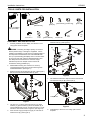
Use 1/4-20 x 3/4" set screw (J) to secure pivot pin (B) to
extension arm (A). (See Figure 2)
If already installed, remove display from Kontour™ arm
using quick connect faceplate.
(K1D100 shown)
(B)
(H)
(C) x 2
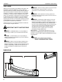
WARNING: Exceeding the weight capacity can result in
serious personal injury or damage to equipment! It is the
installer’s responsibility to make sure the combined weight of
all components located between the K1D100/200 Monitor
Arm up to (and including) the display does not exceed 20 lbs
(9.07 kg) per arm when using the KRA208 extension arm.
Use with products heavier than the maximum weight
indicated may result in collapse of the mount and its
accessories causing possible injury.
2.
Disassemble mounting arm of Kontour™ mount by
unscrewing button head cap screw and removing three
assembled washers. (See Figure 1)
3.
Remove arm from pin by lifting arm off of pin. (See Figure 1)
Set arm and removed hardware aside for reuse.
5 (D)
(G)
(A)
6
(J)
(K1D100 shown)
Figure 2
7.
3
(F)
4
5 (E)
Use hardware removed in Step 2 to attach removed arm
onto extension arm pin (B). (See Figure 3)
removed
washers
2
(K1D100 shown)
7
Kontour arm
removed
screw
(B)
Figure 1
4.
5.
Use 5/16-18 x 1" button head cap screw (F), two steel
washers (C), plastic washer (H) and 5/16" washer (G) to
secure KRA208 arm (A) to pin on base of Kontour™ mount.
Follow the exact order shown in Figure 2. (See Figure 2)
Place chrome ring (D) and pivot ring (E) on outer hole of
extension arm (A). (See Figure 2)
Figure 3
8.
Install display to Kontour™ arm using quick connect
faceplate.
3