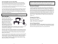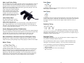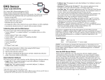
1
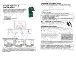
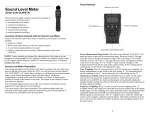
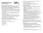
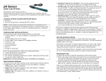
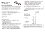
Vernier Photogate (Order Code VPG-BTD) This general-purpose photogate can be used for a wide variety of experiments in physics and physical science classes. Examples include Here is the general procedure to follow when using the Photogate: 1. Connect the Photogate to the interface. 2. Start the data-collection software.1 3. The software will identify the Photogate and load a default data-collection setup. You are now ready to collect data. Data-Collection Software This sensor can be used with an interface and the following data-collection software. Logger Pro 3 This computer program is used with LabQuest 2, LabQuest, LabQuest Mini, or LabPro. Logger Pro 2 This computer program is used with ULI or Serial Box Interface. LabQuest App This program is used when LabQuest 2 or LabQuest is used as a stand-alone device. EasyData App This calculator application for the TI-83 Plus and TI-84 Plus can be used with CBL 2, LabPro, and Vernier EasyLink. We recommend version 2.0 or newer, which can be downloaded from the Vernier web site, www.vernier.com/easy/easydata.html, and then transferred to the calculator. See the Vernier web site, www.vernier.com/calc/software/index.html, for more information on the App and Program Transfer Guidebook. DataQuest™ Software for TI-Nspire™ This calculator application for the TI-Nspire can be used with the TI-Nspire Lab Cradle. DataGate This calculator program can be used with a LabPro or CBL and the following calculators: TI-73, TI-82, TI-83, TI-86, TI-89, TI-92, TI-92 Plus, and Voyage 200. The program is available for download at www.vernier.com/til/2667 LabVIEW National Instruments LabVIEW™ software is a graphical programming language sold by National Instruments. It is used with SensorDAQ and can be used with a number of other Vernier interfaces. See www.vernier.com/labview for more information. measuring freefall acceleration. studying the swing of a pendulum. measuring the speed of a rolling object. timing the period of a rotating object. measuring the speed of objects undergoing collisions. The Vernier Photogate can be used as a traditional photogate for objects traveling between the arms of the gate, and also as a laser gate for objects passing outside of the arms of the gate. A mechanical shutter is used to block the internal gate, switching the device to laser gate mode. The laser gate mode requires a visible pen laser (not supplied). You can expect good results with a typical Class IIIa type laser pointer, with a power of less than 5 mW. The Vernier Photogate can be connected directly to an interface, or in a daisy-chain configuration. In the daisy-chain mode, up to four photogates can be connected to a single channel of the interface by connecting one photogate to another photogate, connecting the last one directly to the interface. Collecting Data with the Vernier Photogate This sensor can be used with the following interfaces to collect data. Vernier LabQuest® 2 or the original LabQuest® as a standalone device or with a computer Vernier LabPro® for use with computers or TI graphing calculators Vernier LabQuest® Mini with a computer Texas Instruments CBL 2™ Universal Lab Interface (ULI) (DG version) Vernier SensorDAQ® TI-Nspire™ Lab Cradle NOTE: Vernier products are designed for educational use. Our products are not designed nor recommended for any industrial, medical, or commercial process such as life support, patient diagnosis, control of a manufacturing process, or industrial testing of any kind. What is Included with the Photogate? The Vernier Photogate includes a cable for connection to one of the interfaces listed above. An accessory rod is included for attachment to a ring stand. 1 If you are using Logger Pro 2 with either a ULI or SBI, the sensor will not auto-ID. Open an experiment file for the Low-g Accelerometer in the Probes & Sensors folder. 2 Internal Gate Mode and Laser Gate Mode The Vernier Photogate operates in two modes. A shutter over the internal gate detector determines the operating mode. The shutter is on the inside of the thinner gate arm. Open the shutter to use the internal gate, and close the shutter to use the external laser gate. A red LED is on when the gate is blocked in either mode. To use the internal gate mode, open the shutter and position the photogate. When the gate is blocked the red LED will be illuminated. To use the external laser gate mode, close the shutter for the internal gate. The laser port is on the outside edge of the gate adjacent to the captive bolt. Align your laser so the beam enters the port and turns off the LED. Blocking the laser beam at any point in its path will then turn the LED back on. The path of the laser need not be a straight line. You may want to use mirrors to create a complex path that is crossed by the moving object multiple times. Laser Safety Note: Do not align the external laser gate by sighting by eye. Follow all safety precautions indicated by the laser manufacturer. Daisy-Chain Mode The Vernier Photogate can be connected in a daisy-chain mode. Connect one gate to the interface, and then connect the next gate to the first Vernier Photogate using the white BTD socket on the arm of the photogate. Up to four Vernier Photogates may be connected to a LabPro interface at one time. The daisy-chain mode requires the cable from the VPG-BTD model. If you have purchased the VPG-DG version for compatibility with your interface, you will need to purchase an additional cable to make each photogate-to-photogate connection (order code PG-BTD). This sensor is equipped with circuitry that supports auto-ID. When used with LabQuest 2, LabQuest, LabQuest Mini, LabPro, SensorDAQ, TI-Nspire Lab Cradle, or CBL 2, the data-collection software identifies the sensor and uses pre-defined parameters to configure an experiment appropriate to the recognized sensor. Mounting the Photogate Connect the clear phone plug from the cable assembly into the modular phone jack on the photogate housing. Plug the other end of the cable assembly into the lab interface or adapter cable. Test the operation of the photogate by watching the LED when the beam is blocked. The LED will go on when the photogate is blocked. The rod included with the photogate can be threaded into the hole in the photogate end to provide a convenient way of mounting the photogate. The rod can be mounted to a ring stand using standard laboratory clamps. Clamp the photogate to a support rod or mounting bracket. For internal gate mode, position the photogate so the object to be timed will pass through the photogate, blocking the beam. For external laser gate mode, it is easier to roughly align the laser, and then position the photogate so the LED goes out. Photogate Specifications Power requirements: 5 VDC at 40 mA Infrared source: Peak at 880 nm Output is high and LED off for unblocked gate Output is low and LED on for blocked gate How the Photogate Works The Vernier Photogate contains two different light detectors. In internal gate mode, a narrow infrared beam is directed to a fast IR detector, which provides very accurate signals for timing. In external laser gate mode, a fast visible light detector located at the end of a tube responds to the presence of a low-power laser beam. In the daisy-chain mode the analyzing software has no way to determine which gate has been blocked, so be sure that this information is not needed. One common setup is to use gate timing, so that the software reports the time a gate is blocked. If you know the order in which gates are blocked from the geometry of the experiment, then daisy mode will work. Note that in a typical collision experiment where two objects are passing through the two gates, the gates may have overlapping block intervals. In this case, you must connect the gates to two separate channels on the interface. Motion timing mode can be used if the daisy-chained gates are equally spaced. Enter the distance between gates in your software to determine position, velocity, and acceleration of a single object passing through a series of photogates. 3 4 Add a Low-Friction Pulley Pulse Timing The Ultra Pulley Accessory (order code SPA) connects to the photogate by using the accessory rod that comes with the photogate. Place the rod though the hole in the photogate and move the pulley into position so that the rod can be threaded into it. Tighten up the rod so that the pulley is held firmly against the photogate. The Ultra Pulley is a low-friction pulley with ten spokes. The spokes break the photogate beam so that the rotation of the pulley can be monitored by the photogate. For example, the motion of an Atwood’s machine could be studied with an Ultra Pulley and the Vernier Photogate. Laser Pointer Stand This light-weight tripod is a perfect support for a laser pointer. The stand features fold-out legs and a clip attached to the adjustable ball. A socket head assembly securely holds the laser in place. This assembly allows you to accurately point the laser at the photogate. A VELCRO® strap integrated into one of the tripod legs allows you to attach the laser to objects such as ring stands and railings. Vernier Photogate and Early TI Publications The Vernier Photogate should not be used as a replacement for the simple photogates (using the TI light sensor) described in the CBL Experiment Workbook (which comes with the CBL) or in Exploring Physics and Math with the CBL System. The programs used with these books will not work with this type of photogate. More Information on Geometric Aspects of Photogate Timing Photogates have a number of geometric complications that result in the effective length of an object passing through the gate being slightly less than the actual length. In this mode, a measurement from when a photogate gets blocked to when it gets blocked again will be recorded. Gate Timing For this mode, timing will begin when the photogate is first blocked. The timing will continue until the gate is unblocked. The duration of the interruption is thus timed. If the length of the object is entered in the Length of Object field, the velocity is calculated. Pendulum Timing the Pendulum Timing mode uses a photogate connected to an interface. The timing will begin when the photogate is first interrupted. The timing will continue until the photogate is interrupted twice more, so that you get the time for a complete swing of a pendulum or other oscillating object. Photogate Timing In Photogate Timing mode, only a time and Gate State column are displayed. You may add other calculated columns as desired. For a good discussion of these issues, see Eugene P. Mosca and John P. Ertel, “Photogates: An instrument evaluation,” Am. J. Phys. 57 (9), 840-844 (1989). Motion Timing The Motion Timing mode uses a photogate or pulley connected to the digital input. During operation, times are recorded as leading opaque edges of a “picket fence,” bar tape, or a pulley spoke pass through the photogate beam. These times are displayed in a data table. More importantly, if you enter the distance between the leading edges of the opaque bands in the Length of Object field, the program can analyze the times, and calculate velocities, displacements, and accelerations. 5 A more comprehensive tutorial can be found in the following documents: Logger Pro Introduction to the Vernier Photogate http://vnr.st/xe80 LabQuest Introduction to the Vernier Photogate http://vnr.st/xe6f 6 Experiments Using the Vernier Photogate The Vernier Photogate is used in several experiments in the book Physics with Vernier published by Vernier Software & Technology. See this book for detailed experiments. Here are some brief examples of things you can do with a photogate. 1. If you know the diameter of a ball rolling through a photogate, you can determine the speed of the ball from the ratio of the diameter to the time the gate is blocked by the ball. This requires only one gate, but the gate has to be positioned carefully so the light beam intersects the middle of the ball. 2. Using two photogates positioned at a known separation, you can determine the speed of an object from the time interval between the breaking of the first beam to the breaking of the second. This mode is known as pulse timing. 3. Set up a pendulum so that the bob swings through the photogate. The time interval from one block to the third block yields the pendulum period. 4. Use the laser gate at floor level to measure the “hang time” of a jumper. The jumper’s shoes will block the beam while on the floor. The time interval of interest is then the unblock to block time. 5. Use a super pulley to construct an Atwood’s machine, consisting of two masses connected by a flexible string. The string passes over the pulley, causing it to rotate as the masses move. Use motion timing to measure the position, velocity, and acceleration as a function of time. 6. Measure the free fall acceleration of a picket fence using either the internal gate or the laser gate. Motion timing will give you the position, velocity, and acceleration as a function of time. Do the two modes give different results? Warranty Vernier warrants this product to be free from defects in materials and workmanship for a period of five years from the date of shipment to the customer. This warranty does not cover damage to the product caused by abuse or improper use. Vernier Software & Technology 13979 S.W. Millikan Way Beaverton, OR 97005-2886 Toll Free (888) 837-6437 (503) 277-2299 FAX (503) 277-2440 [email protected] www.vernier.com Rev. 12/20/2012 Logger Pro, Logger Lite, Vernier LabQuest 2, Vernier LabQuest, Vernier LabQuest Mini, Vernier LabPro, Go! Link, Vernier EasyLink and other marks shown are our trademarks or registered trademarks in the United States. TI-Nspire, CBL 2 and CBL, TI-GRAPH LINK, and TI Connect are trademarks of Texas Instruments. All other marks not owned by us that appear herein are the property of their respective owners, who may or may not be affiliated with, connected to, or sponsored by us. Printed on recycled paper. 7 8