1
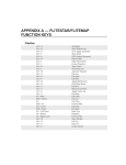
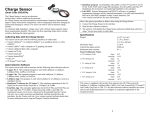
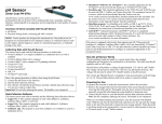
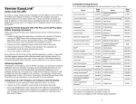
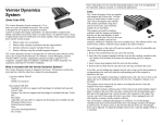
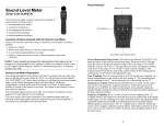
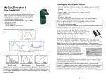
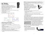
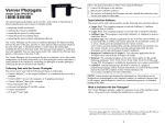
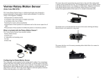
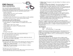
Flow Rate Sensor (Order Code FLO-BTA) The Flow Rate Sensor measures the velocity of water in a river, stream, or canal. It can be used to study the discharge, flow patterns, and sediment transport of a stream or river. Inventory of Items Included with the Flow Rate Sensor Check to be sure that each of these items is included in your Flow Rate Sensor package: Flow Rate Sensor (impeller rod with 5 meter cable) Three riser rods (short, medium, and long) Collecting Data with the Flow Rate Sensor This sensor can be used with the following interfaces to collect data. Vernier LabQuest® 2 or original LabQuest as a standalone device or with a computer Vernier LabQuest® Mini with a computer Vernier LabPro® with a computer or TI graphing calculator Vernier Go!®Link Vernier EasyLink® Vernier SensorDAQ® CBL 2™ TI-Nspire™ Lab Cradle Here is the general procedure to follow when using the Flow Rate Sensor: 1. Connect the Flow Rate Sensor to the interface. 2. Start the data-collection software.1 3. The software will identify the Flow Rate Sensor and load a default data-collection setup. You are now ready to collect data. Data-Collection Software This sensor can be used with an interface and the following data-collection software. Logger Pro 3 This computer program is used with LabQuest 2, LabQuest, LabQuest Mini, LabPro, or Go!Link. Logger Pro 2 This computer program is used with ULI or Serial Box Interface. Logger Lite This computer program is used with LabQuest 2, LabQuest, LabQuest Mini, LabPro, or Go!Link. 1 If you are using Logger Pro 2 with either a ULI or SBI, the sensor will not auto-ID. Open an experiment file for the Flow Rate Sensor in the Probes & Sensors folder. LabQuest App This program is used when LabQuest 2 or LabQuest is used as a standalone device. EasyData App This calculator application for the TI-83 Plus and TI-84 Plus can be used with CBL 2™, LabPro, and Vernier EasyLink. We recommend version 2.0 or newer, which can be downloaded from the Vernier web site, www.vernier.com/easy/easydata.html, and then transferred to the calculator. See the Vernier web site, www.vernier.com/calc/software/index.html for more information on the App and Program Transfer Guidebook. DataMate program Use DataMate with LabPro or CBL 2™ and TI-73, TI-83, TI-84, TI-86, TI-89, and Voyage 200 calculators. See the LabPro and CBL 2™ Guidebooks for instructions on transferring DataMate to the calculator. DataQuest™ Software for TI-Nspire™ This calculator application for the TI-Nspire can be used with the EasyLink or TI-Nspire Lab Cradle. LabVIEW National Instruments LabVIEW™ software is a graphical programming language sold by National Instruments. It is used with SensorDAQ and can be used with a number of other Vernier interfaces. See www.vernier.com/labview for more information. NOTE: Vernier products are designed for educational use. Our products are not designed nor recommended for any industrial, medical, or commercial process such as life support, patient diagnosis, control of a manufacturing process, or industrial testing of any kind. Storage and Maintenance of the Flow Rate Sensor When you have finished using the Flow Rate Sensor, simply rinse it with clean water and dry it using a paper towel or cloth. The probe can then be folded up and stored. To prolong the life of your Flow Rate Sensor, we recommend that the moving parts of the impeller rod be lubricated with WD-40®, or a similar lubricant, after every few field uses. When using the impeller rod, avoid hitting the impeller blade on rocks and other hard surfaces. If the impeller blade is bent, it will decrease the accuracy of the sensor. Specifications Range: 13-bit resolution (SensorDAQ): 12-bit resolution (LabPro, LabQuest 2, LabQuest, LabQuest Mini, Go!Link, and TI-Nspire™ Lab Cradle): 10-bit resolution (CBL 2™): Accuracy: Response time: 0 to 4.0 m/s (0 to 13 ft/s) 0.0006 m/s 0.0012 m/s Temperature range (can be placed in): Stored Calibration Values slope: intercept: 2 0.005 m/s ±1% of full-scale reading 98% of full-scale reading in 5 seconds, 100% of full-scale in 15 seconds. 0 to 70°C 1 m/s/V 0 m/s This sensor is equipped with circuitry that supports auto-ID. When used with LabQuest 2, LabQuest, LabQuest Mini, LabPro, Go! Link, SensorDAQ, TI-Nspire™ Lab Cradle, EasyLink, or CBL 2™, the data-collection software identifies the sensor and uses pre-defined parameters to configure an experiment appropriate to the recognized sensor. How the Flow Rate Sensor Works The Vernier Flow Rate Sensor measures the velocity of flowing water. When placed in a stream, as shown here, water flows against the blades of the impeller, causing it to turn. The faster the water flows, the faster the impeller turns. A bar magnet rotating with the impeller triggers a reed switch with each half rotation. The switch sends a pulse to the signal conditioning box, where the pulses are converted into a voltage that is proportional to flow rate. Flow rate can be measured in m/s or ft/s. reed switch bar magnet impeller Front Back Calibration Information We feel that you should not have to perform a new calibration when using the Flow Rate Sensor in the classroom. We have set the sensor to match our stored calibration before shipping it. You can simply use the appropriate calibration file that is stored in your data-collection program. Sediment Transport The amount of sediment and maximum particle size that can be transported by moving water is related to the flow velocity. Therefore, flow velocity data obtained using the Flow Rate Sensor can be used to determine what size particles will stay in motion at a particular flow velocity. This chart, derived from accumulated observed data, shows that for a given flow velocity there is a range of behavioral possibilities for sediment particles lying on the bed, or entrained within the flow, of a stream. At a measured flow velocity of 1 m/s, silt and sand (though not compacted clay) will be eroded from the stream bed and transported downstream. At the same velocity, all sediment particles between 10 mm and 100 mm that were already in motion will continue in motion. Particles greater than 100 mm will be deposited. A Flow Rate Sensor can be a valuable observational tool when used in sediment transportation studies. Describing Flows Using the Flow Rate Sensor, it is possible to map flow characteristics of a stream by taking measurements at different spots and depths. To understand the flow characteristics within streams of moving water, it is helpful to construct Stream Lines and Vector Lines. The illustration shown here shows how Stream Lines depict possible paths of a single fluid particle. Vector Lines represent both the flow rate and direction. The longer and broader the line, the greater the flow velocity. Vector Lines convey useful information about the stream flow characteristics. Uses of the Flow Rate Sensor Calculating Discharge To determine the amount of water flowing in a stream, you need to measure the rate at which the water flows and the area the water occupies at a specific point in the stream. The discharge, or stream flow, is the flow rate multiplied by the area of water. Flow Rate Area of Cross Section = Discharge or Stream Flow Detailed instructions on collecting flow rate data and calculating discharge can be found in the next section of this booklet. 3 Stream Flow (Sample Activity) 4 2. Using the meter stick, measure the depth of the stream in meters at each of the equally spaced points along the cross section. Record the depth and the distance out from one shore edge, in meters, on a data sheet. Always measure from the same shore. Be sure to include both the initial distance and depth and the final distance and depth. 1 2 3 4 Initial distance = 0 5 6 7 Final distance = Stream width Initial depth = 0 Final depth = 0 distance out Measuring Flow Velocity 3. Connect the Flow Rate Sensor to the interface and start the data-collection program. 4. Collect stream flow data. a. Use the Stream Flow experiment file in Logger Pro or set up the program for single point data collection. b. Submerge the impeller of the Flow Rate Sensor to about 40% of the depth measured at each section. If the section is shallow enough, use the plastic risers that are included with the flow rate sensor to support the sensor on the stream bed. The risers make it easier to keep the impeller of the sensor in the same spot and oriented in 40% the same direction. risers optional Testing Procedure Measuring a Stream Cross Section 1. Using the measuring tape, determine the width of the stream cross section in meters and record the measurement on a data sheet. Divide the cross section into six equally spaced sections. 1 depth Site Selection 1. Select two sites within a 50 m stretch of the stream Avoid stream that are as far apart as possible and are beds representative of the stream as a whole. Avoid sites Avoid logs with bends or breaks in the stream caused by rocks or and rocks sandbars. Try to choose a site where some flow can be observed. One site can have a swift flow similar to Site that found in a riffle. The second site can have a moderate or slow flow like that found after a pool. It is not necessary for both sites to be the same. Avoid 2. At each site, you are going to take a cross section of sandbars the stream and measure its width and depth. Try to select a cross section that is shallow enough to measure depth with a meter stick and easy to cross. To measure stream flow using the Flow Rate Sensor, avoid sites where the stream depth is less than 10 cm. 3. The Flow Rate Sensor is equipped with a 5 m cable. This enables you to take measurements up to 4 m away from the shore without carrying the interface Site out into the stream. If the stream is wider than 4 m, monitor the stream flow out from one shore line, then have the person holding the interface switch to the other side of the stream. This should reduce the chances of dropping the equipment into the water and damaging it. 4. Always follow safety precautions when entering the stream. If the water is too deep or swift, select another site. Never venture out into the stream alone without another person available to assist you in case of emergency. Flow c. Point the impeller of the sensor upstream (as shown below) and directly into the flow. Select START or to begin sampling. Hold the sensor in place for 10 seconds while data are being collected. Once data collection is finished, the flow rate will be displayed. Record the reading on the Data & Calculations sheet. Repeat for each of the remaining sections. Calculating Stream Flow 5. Create a graph of stream depth vs. distance from the shore. 6. Integrate the data. The integral value will give you the cross-sectional area of the stream. Determining Discharge 7. Calculate the average velocity for each site. 8. To calculate the discharge or stream flow, multiply the average stream velocity by the cross-sectional area. Repeat for Site 2. To convert from m3/s to cubic feet per second, multiply by 35.315. 5 6 Detailed instructions for data collection with computers, LabQuest, TI graphing calculators, and Palm Powered handhelds may be found in our Water Quality with Vernier lab book. The Stream Flow test is test number 16 in this book. Additional Information for Instructors Warranty Vernier warrants this product to be free from defects in materials and workmanship for a period of five years from the date of shipment to the customer. This warranty does not cover damage to the product caused by abuse or improper use. Safety Tips 1. Follow safety guidelines when students are working in or near water. Avoid sites where the water is deep or swift. Water with a flow velocity of 0.5 m/s or greater is considered to be swift. Water with a depth greater than the top of your knee should be considered deep. 2. Never work alone around a stream. Students should always work with others in groups of 2–3. Do not allow students to wander away from their group. It is important to know where student groups are at all times. Students should not change locations without notifying their instructor first. 3. Before using a particular site, it is best to survey the area for unseen dangers, such as unstable banks, dangerous obstacles in the stream, or fallen trees. Avoid these possible dangers. 4. Always be careful when crossing a stream. If it looks dangerous, select another spot in the stream to cross. 5. Students should wear warm, waterproof clothes when working in a stream. If possible, they should bring spare items such as dry socks that can be worn after working in the water. Prolonged exposure to cold waters can result in hypothermia, which can be a life-threatening condition. Additional Tips 1. The plastic risers that come with the Flow Rate Sensor can be very helpful in keeping the sensor at the same orientation while taking measurements. When using the risers, simply place the bottom of the sensor rod against the stream bottom. If you are risers unsure which riser to use, start with the medium optional 3 risers riser first and gauge the depth from there. included 2. When students are selecting sites to take flow measurements, they should choose a site where the stream is not split by rocks, partially submerged obstructions, or sand bars. 3. The impeller of the flow rate sensor should always be pointing into the flow when measurements are being made. Students need to stand on the shore when taking measurements close to the shore, or stand as far downstream as possible from the sensor when placing the sensor in deeper water. 4. Because stream flow is easily affected by weather conditions, it is important that good notes concerning date, time, and weather be taken whenever flow measurements are made. Vernier Software & Technology 13979 S.W. Millikan Way Beaverton, OR 97005-2886 Toll Free (888) 837-6437 (503) 277-2299 FAX (503) 277-2440 [email protected] www.vernier.com Rev. 6/5/2012 Logger Pro, Logger Lite, Vernier LabQuest 2, Vernier LabQuest, Vernier LabQuest Mini, Vernier LabPro, Go! Link, Vernier EasyLink and other marks shown are our trademarks or registered trademarks in the United States. TI-Nspire, CBL 2, TI-GRAPH LINK, and TI Connect are trademarks of Texas Instruments. All other marks not owned by us that appear herein are the property of their respective owners, who may or may not be affiliated with, connected to, or sponsored by us. Printed on recycled paper. 7 8