1
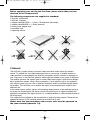
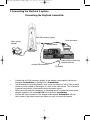
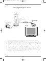
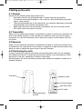
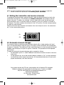
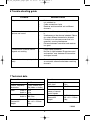
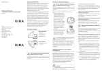
bed_anl_SkyFunk3_engl.qxd
25.09.03
09:07
Seite 1
Operating manual
SkyFunk 3
2,4 GHz wireless transmission system
bed_anl_SkyFunk3_engl.qxd
25.09.03
09:07
Seite 2
Contents
Chapter
1
2
3
4
5
6
7
Topic . . . . . . . . . . . . . . . . . . . . . . . . . . . . . . . . . . . . . . . . . . . . . . . . . . . . .Page
Safety advice . . . . . . . . . . . . . . . . . . . . . . . . . . . . . . . . . . . . . . . . . . . . . . . .2
General . . . . . . . . . . . . . . . . . . . . . . . . . . . . . . . . . . . . . . . . . . . . . . . . . . . .3
Connections . . . . . . . . . . . . . . . . . . . . . . . . . . . . . . . . . . . . . . . . . . . . . . . . .4
Setting up the units . . . . . . . . . . . . . . . . . . . . . . . . . . . . . . . . . . . . . . . . . . .6
Operation . . . . . . . . . . . . . . . . . . . . . . . . . . . . . . . . . . . . . . . . . . . . . . . . . . .7
Trouble-shooting guide . . . . . . . . . . . . . . . . . . . . . . . . . . . . . . . . . . . . . . . .8
Technical data . . . . . . . . . . . . . . . . . . . . . . . . . . . . . . . . . . . . . . . . . . . . . . .8
European regulations:
TechniSat hereby declares that the product SkyFunk 3 is in accordance with the basic requirements as well as all other relevant regulations of Guideline 1999/5/EG.
In accordance with this guideline, the product may be operated in the following countries
The complete original Declaration of Conformity can be found in the Internet at the following
address:
D
ü
A
ü
http://www.technisat.de/konformitaet/skyfunk3.pdf
1 Safety advice
For your own protection, you should read the safety precautions carefully before operating
your new unit for the first time.
The manufacturer accepts no liability for damage or injuries caused by inappropriate handling of the product, or by non-compliance with the safety precautions.
>
Do not open the housing of the unit, under any circumstances. You are in danger of
receiving an electrical shock. If it ever becomes necessary to open the unit, this
should be carried out only by trained personnel.
In the following cases you should disconnect the unit from the mains
power supply, and contact a qualified expert for assistance:
>
the mains cable or plug are damaged
>
the unit was exposed to extreme humidity, or water has entered it
>
in case of severe malfunctions
>
in case of significant exterior damage.
When not in operation:
During an electrical storm, or when it is not being operated for an extended period of time,
the unit should be disconnected from the mains power supply.
2
bed_anl_SkyFunk3_engl.qxd
25.09.03
09:07
Seite 3
Before operating your unit for the first time, please check that you have
received all the components!!!
The following components are supplied as standard:
1 SkyFunk 3 transmitter
1 SkyFunk 3 receiver
1 adapter cable Mini DIN <---> Scart + IR extension (transmitter)
1 adapter cable MiniDIN <---> Scart (receiver)
2 mains power adapter units
1 guarantee card
1 Operating manual
2 General
The SkyFunk 3 system serves to transmit video and stereo audio signals by wireless
means. To achieve this, the video/audio signal from a source (e.g. a satellite receiver or
video recorder) is transmitted by the SkyFunk transmitter, which is located, for example, in
your living room, to the SkyFunk receiver, which might be located in your study or bedroom.
The receiver converts the signals back to normal video/audio signals, which can be displayed on a television screen, using a Scart connection. If your television set is not equipped
with a Scart socket, you can use an external modulator, which is available through specialist retailers. This will allow you to receive the signal via the antenna input socket of your
television set.
In the same manner, control signals of the existing remote control at the receiving end (e.g.
the study) are transmitted to the signal source, thus allowing you to operate remotely the
appliance connected at the signal source (i.e. a satellite receiver or video recorder located in
the living room).
Four channels are available for the transmission of audio and video signals. These can be
selected by means of DIP switches located on the SkyFunk 3 units.
Please note that the transmitter and receiver units must be operated on
the same channel (channels 1-4).
3
bed_anl_SkyFunk3_engl.qxd
25.09.03
09:07
Seite 4
3 Connecting the SkyFunk 3 system
Connecting the SkyFunk transmitter
Mini DIN connector (green)
Scart connector
Mains power
adapter
Adapter cable
Transmitter
Transmitter
Video-/Audio source (e.g.
satellite receiver)
Infrared (IR) extension
>
>
>
>
IR window
Connect the mini DIN connector (green) of the adapter cable supplied, carring the
inscription Transmitter to the SkyFunk 3 Transmitter.
The IR-extension should be placed in such a way that there is a line of sight to the IR
window (usually located on the display of a unit) of the video source. This is essential
to ensure transmission of the remote control command signals.
When you have made the connection as described above, connect the mains power
adapter supplied to the socket DC 9V of the SkyFunk transmitter
Connect the Scart connector of the adapter cable marked transmitter with the
Scart socket of the video source from which you wish to transmit the signals.
4
bed_anl_SkyFunk3_engl.qxd
25.09.03
09:07
Seite 5
Connecting the SkyFunk receiver
Mini DIN connector
(violet)
Mains power
adapter
Adapter cable
Scart connector
Receiver
TV set
Receiver
>
>
>
>
Connect the Mini DIN connector (violet) of the adapter cable supplied, labelled
Receiver with the SkyFunk 3 receiver.
The SkyFunk receiver should be positioned in such a way that the red IR window has
an unobstructed line of sight to the remote control unit. This is essential to ensure the
remote control command signals are transmitted.
When you have made the connection described above, connect the mains power
adapter supplied with the socket DC 9V of the SkyFunk 3 receiver.
Connect the Scart connector of the adapter cable labelled receiver with the Scart
socket of your television set. Youi can now receive and view the signals received via
the SkyFunk receiver on the programme slot AV.
5
bed_anl_SkyFunk3_engl.qxd
25.09.03
09:07
Seite 6
4 Setting up the units
4.1 General
Please note the following when setting up the units:
>
If possible, the units should be positioned 1-2 metres above the ground/floor
>
To avoid the units being damaged in a fall to the floor, they should always be positioned on a level surface.
>
There should preferably be as few obstructions (e.g. electrical appliances) as possible
located between the transmitter and receiver units.
>
Make certain that both units (transmitter and receiver) are set to the same channel
(DIP switch on the rear panel of the units.
4.2 Transmitter
When you have made the connections as described in chapter 3, position the transmitter unit
close to the satellite receiver or video recorder from which you wish to transmit the signal,
and position it so that the IR extension has a direct line of sight to the IR window of the signal source.
4.3 Receiver
When you have made the connections as described in chapter 3, position the receiver close
to the television set, and position it so that there is a direct line of sight from the position from
which you wish to operate the signal source to the red IR window.
4.4 Positioning the units
In order to achieve an optimum transmitting and receiving quality, both units are equipped
with directional antennae. To optimise the transmission quality, it may be necessary to alter
the position of the units, specifically in relation to each other.
Should reception still not be satisfactory, please check whether the reception is better on an
alternative channel.
IR window
Mains switch
Channel selector
Mini DIN socket
DC socket
Stand (illuminated
by LED)
6
bed_anl_SkyFunk3_engl.qxd
25.09.03
09:07
Seite 7
5 Operation
When you have worked through all the points, your SkyFunk 3 is ready for operation.
>
Switch on both units by means of the mains power switches.
5.1 Setting the transmitter and receiver channels
To change the transmitter resp. receiver channel, select the desired channel on both units
(transmitter and receiver). The switches for channel selection are located on the rear
panel of the units. To select, e.g., channel 1,use an object with a small tip (ball-point pen,
small screwdriver, etc.) to move the switch for channel 1 to the “On” position, as shown in
the diagram. The other switches should be left in the “Off” position. Use the same procedure
to select any other channel.
Please ensure that the transmitter and receiver units must always be set to the same channel, i.e. the same switch position.
ON
DIP
On
Off
1
2
3
4
5.2 Automatic channel changes
You have the facility of receiving several different signals with a single receiver unit (maximum of 4 channels).When using this option, the signal of each transmitter will be displayed
for approx. 5 seconds. The receiver will then automatically go on to the next receiver channel
selected, and will display its signal for approx. 5 seconds. This procedure will be repeated
continuously.
To select the automatic channel changing option, proceed as follows:
>
As described in point 5.1, select a different transmission channel on each of the transmitter units.
>
On the receiver unit, set all the channel selector switches to “On”, for those channels
on which there will be signal transmissions. All the selected channels will now be displayed automatically, one after the other.
Your product carries the CE mark, and complies with all relevant EU standards.
Subject to change. Not responsible for printing errors. Correct as at 09/03
SkyFunk and TechniSat are registered trademarks of
TechniSat Digital GmbH
P.O. Box 560 - D-54541 Daun
www.technisat.de
7
bed_anl_SkyFunk3_engl.qxd
25.09.03
09:07
Seite 8
6 Trouble-shooting guide
Problem
No picture, no sound
Possible cause
>
>
>
Interference in transmission of
picture and sound
>
>
>
>
Mains switch or receiver and/or transmitter
not switched on
Cable connections faulty
Receiver and transmitter set to different
channels
Antennae of the system not aligned optimally
Interference on the channel selected. Remedy: select different transmission channel.
Proximity to a microwave oven that is in
operation, causing interference.
Distance between transmitter and receiver
too great.
Transmission of remote control
signals not working
>
>
Faulty cable connection
No line of sight between IR remote control
and receiver, resp. between IR transmitter
and signal source.
Transmission interrupted periodically
>
Several receiver channels set, this leads to
an automatic alternation between receiving
channels.
7 Technical data
Transmitter
Output level
10 dBm
Transm. frequency
Modulation
2,4 bis 2,4835 GHz
FM (Video u. Audio)
Level
Video in 1Vss
Audio in 1Vss
Impedance Video in 75 Ohm
Audio in 600 Ohm
Power supply
Dimensions
Weight
9V DC 90mA
102 x 41 x 115mm
130g
Receiver
Video level
Audio level
1Vss
1Vss
Sensitivity
-85 dBm
Transmission frequency of remote
control signals
434 MHz
IPower supply
Dimensions
Weight
9V DC 90mA
102 x 41 x 115mm
130g
110903
8