1
WBM2E
Installation Instructions
3.
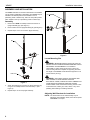
Drill one 1/4" x 2-3/4" pilot hole at each marking. (See
Figure 5)
4.
Install a toggler (B) into each pilot hole using a hammer.
(See Figure 5)
5.
3.
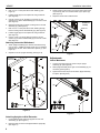
Fasten upright in place using one 1/4-20 x 3/8" button head
cap screw (F) and one .4"x.255"x.0625" nylon spacer (S).
(See Figure 7)
4.
Repeat for other side of wall extrusion.
Use two 1/4-20 x 2-1/2" lag bolts (C) and two 1/4" flat
washers (A) to attach wall assembly (K) to anchors in wall.
(See Figure 5)
6.
Mark the wall through the lower mounting hole in the wall
assembly (K). (See Figure 5)
7.
Drill one 1/4" x 2-3/4" pilot hole at each marking through
lower mounting hole in wall assembly (K). (See Figure 5)
8.
Install a toggler (B) into each pilot hole using a hammer.
(See Figure 5)
9.
Use two 1/4-20 x 2-1/2" lag bolts (C) and two 1/4" flat
washers (A) to attach wall assembly (K) to anchors in wall.
(See Figure 5)
(Interactive
board not
shown)
(K)
Slide nut
1
(F) x 1
3
Attaching Interactive Whiteboard
1.
2.
(D)
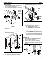
Attach upright assembly (D) to back of white board using
four 1/4-20 x 1" Phillips pan head screws (H), four isolation
washers (G) and four .500"x.320"x.425" spacers (J). (See
Figure 6)
(S) x 1
Repeat for second upright assembly. (See Figure 6)
Figure 7
Interactive
white board
(D) x 2
Adjustments
Lateral Movement
1.
Loosen one button head cap screw at top of upright
assembly (D). (See Figure 8)
2.
Slide upright assembly left or right on wall assembly (K), as
necessary. (See Figure 8)
3.
Tighten button head cap screw to fasten upright assembly
into place. (See Figure 8)
(K)
(J) x 4
2
(G) x 4
(D)
1
1
2
(H) x 4
3
x1
Figure 6
Figure 8
Attaching Uprights to Wall Extrusion
1.
Hook whiteboard with attached uprights onto the wall
asssembly (K). (See Figure 7)
2.
Move the slide nut so that it is aligned with the upright (D).
(See Figure 7)
8