1
DIN-Rail Mounting
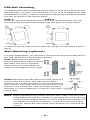
The DIN rail attachment plate should already be fixed to the back panel of
INJ-24A when you take it out of the box. If you need to reattach the DIN
Rail attachment plate, make sure the stiff metal spring is situated towards
the top, as shown in the figures below.
STEP 1:
STEP 2:
Insert the top of the DIN rail into theThe DIN rail attachment unit will
slot just below the stiff metal spring.snap into place as shown below.
To remove the INJ-24A from the DIN rail, simply reverse steps 1 and 2
above
Wall Mounting (optional)
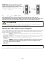
For some applications, you will find it convenient to mount the INJ-24A on
the wall, as shown in the following figures.
STEP 1: Remove the aluminum
DIN rail attachment plate from the
INJ-24A’s rear panel, and then
attach the wall mount plates as
shown in the diagram to the right.
STEP 2: Mounting the INJ-24A on the wall requires 4
screws. Use the switch, with wall mount plates
attached, as a guide to mark the correct locations of
the 4 screws. The heads of the screws should be less
than 6.0 mm in diameter, and the shafts should be
less than 3.5 mm in diameter, as shown in the figure
at the right.
NOTE
Before tightening the screws into the wall, make sure the screw
head and shank size are suitable by inserting the screw into one
of the keyhole-shaped apertures of the wall mounting plates. Do
not tighten the screws completely—leave about 2 mm to allow
room for sliding the wall mount panel between the wall and the
screws.
-6-