1
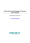
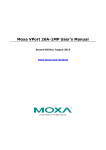
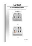
MOXA IP Camera VPort P06HC-1MP-M12 Quick Installation Guide First Edition, December 2013 2013 Moxa Inc. All rights reserved. P/N: 1802000061010 Overview The VPort P06HC-1MP-M12 series is a square, flush mount, HD (720P, 1280 x 720) video image, H.264/MJPEG IP camera designed for mobile video surveillance applications. It features EN 50155 compliance, a -25 to 55°C operating temperature, rugged M12 Ethernet port, 1 microphone, 1 digital input PoE power input, IP66 rain and dust protection, and selectable lens models, for the versatility and ruggedness required to excel in many different installations and environments for mobile IP video surveillance applications. Package Checklist Moxa’s VPort P06HC-1MP-M12 is shipped with the following items. If any of these items are missing or damaged, please contact your customer service representative for assistance. 1 × VPort P06HC-1MP-M12 (lens included) Standard Temperature Models VPort P06HC-1MP-M12-CAM36 Lens 3.6 mm Accessories Package Torx screw driver for loosening the camera’s front lens cover Silica gel dessicant and hook fastener for absorbing the moisture inside the camera 2 L-type installation kits and 4 nylock screws for mounting the camera Sticker for Camera Mounting Positions Quick Installation Guide Documentation and Software CD (includes User’s Manual, Quick Installation Guide, and VPort Utility) Warranty card -2- NOTE Check the model name on the VPort’s side label to determine if the model name is correct for your order. NOTE This product must be installed in compliance with your local laws and regulations. Features • • • • • • • • • • • • • • • • • • • • • • • • • • • • • • • • • • 1/2.7”HD progressive CMOS image sensor Video stream up to 30 frames/sec at WXGA (1280x800) resolution High image quality with WDR (wide dynamic range) and DNR (Digital Noise Reduction) supported Minimum illumination is up to 0.2 lux (color) Supports MJPEG and H.264 Dual Codecs Provides 3 video streams for H.264 and MJPEG simultaneously Supports video quality configuration with fixed bit rate (CBR) and fixed quality (VBR) Video latency under 200 ms DynaStream™ for network efficiency with dynamic frame rate change CBR Pro™ supported for high image quality in limited bandwidth transmissions WXGA/720P/SVGA/Full D1/4CIF/VGA/CIF/ QCIF resolution TCP, UDP, and HTTP network transmission modes Supports DHCP OPT66/67 for automatic configuration from a TFTP server, making it easy to batch configure several units Supports RTSP streaming Supports multicast (IGMP) video streaming Supports SNMP (V1/V2C/V3) for network system integration and management Supports QoS (ToS) for transmission priority Built-in web server for easy configuration Accessible IP filtering UPnP supported Compliant with EN 50121-3-2 and relevant sections of EN 50155 (compliant with IEC 60571) 1 10/100BaseT(X) port with M12 D-code connector 1 built-in microphone for audio input 1 digital input with 5-pin M12 connector for external events IP66 rain and dust protection PoE (Power-over-Ethernet, IEEE 802.3af) supported -25 to 55°C (EN 50155, class T1) operating temperature for rolling stock environments CE, FCC, UL 60950-1 Built-in tamper alarm and Video Motion Detection (VMD) Pre, Trigger, and post snapshot images supported Sequential snapshot images supported Supports SMTP and FTP for alarm message transmission Supports HTTP event server 5-year warranty -3- Product Description Appearance • 4-pin female D-code M12 Ethernet connector: Can be used for both the PoE power supply (Mode A) and Auto MDI/MDI-X Ethernet connection NOTE To connect the VPort P06HC-1MP-M12 to a network, use an Ethernet cable with D-code M12 connector and an M12 PoE switch or RJ45 PoE switch. M12 male to M12 male cable M12 PoE Switch (e.g., TN-5508-4PoE) M12 male to RJ45 cable RJ45 PoE switch (e.g., EDS-P510) NOTE The power input rating of the VPort P06HC-1MP-M12 is 48 VDC, 0.13 A, with maximum power consumption approximately 6.3 W. -4- NOTE The equipment is designed for in building installation only and is not intended to be connected to exposed (outside a plant) networks • 5-pin M12 male connector: The VPort P06HC-1MP-M12 supports one digital input with 5-pin M12 male connector. This DI is used for connecting with external device for triggering an event or alarm. • Digital input Max. 8 mA, Low: +13 V to +30 V; High: -30 V to +3 V NOTE This digital input is for connecting with an external device, such as a button, for triggering an event and alarm. The VPort P06HC-1MP-M12 can send messages via an IP network to the management software at a remote site. • Built-in microphone: The VPort P06HC-1MP-M12 is equipped with a built-in microphone to receive external sounds. The sound will be digitized and compressed as an audio stream for network transmission with the video stream. NOTE The effective distance for the VPort P06HC-1MP-M12’s built-in microphone is 100 cm. • Removable lens cover: The VPort P06HC-1MP-M12 is designed with a removable cover for fine-tuning the lens angle manually. The user can remove this lens cover after loosening the 6 torx screws. NOTE The VPort P06HC-1MP-M12’s optical lens cover is coated with a high performance waterproof coating. Please use the scrubbing cloth to light clean the cover. NOTE The color of the lens cover can be customized based on your installation environment. Please contact your Moxa sales representative for customization service. -5- Inside the Camera • • • Thumb screw for fixing the lens’s position: To tune the lens’s position, loosen the thumb screw, and then retighten it after the position tuning is done. Lens with fixed focal length: The VPort P06HC-1MP-M12 series supports a fixed focal-length lens. Choose the appropriate focal-length lens based on the viewing angle and object distance. Board plate screws: these 2 screws are for loosening the board plate, which can be pulled out for tuning the camera lens position. Hardware Installation NOTE To flush mount the VPort P06HC with an intercom, use the VP-FD1 accessory (must be ordered separately) to install the camera. If you do not want to use the VP-FD1, refer to the dimensions on the installation sticker for customizing your own installation. using the VP-FD1 for installing with an intercom -6- VP-FD1 Step 1: Screw the 2 L-type installation plates onto the VPort P06HC. Vertical mountable Horizontal mountable Step 2: Use the installation sticker to drill the holes for flush-mounting the VPort P06HC with the VP-FD1. -7- NOTE The screw holes for mounting the 2 VP-FD1’s mounting kits are countersunk holes with 8 mm top diameter and 4.3 mm chamfer. Take this into consideration when drilling these 4 screw holes. Step 3: Install the VP-FD1’s mounting kit. Screw 4 nylock M4 screws on the 4 countersunk screw holes with 2 VP-FD1’s mounting kits. Front view Rear view Step 4: Connect the VPort P06HC’s connectors. -8- Step 5: Mount the VPort P06HC with the VP-FD1’s mounting kit. Step 6: Mount the VP-FD1’s front decorative plate on the wall. NOTE The type and color of VP-FD1 can be customized by request. Please contact a Moxa sales representative for this customization service. -9- Software Installation Step 1: Configure the VPort P06HC-1MP-M12’s IP address. When the VPort P06HC-1MP-M12 is first powered on, the POST (Power On Self Test) will run for a few moments (about 30 seconds). The network environment determines how the IP address is assigned. Network Environment with DHCP Server For this network environment, the unit’s IP address will be assigned by the network’s DHCP server. Refer to the DHCP server’s IP address table to determine the unit’s assigned IP address. You may also use the Moxa VPort and EtherDevice Configurator Utility (edscfgui.exe), as described below: Using the Moxa VPort and EtherDevice Configurator Utility (edscfgui.exe) 1. Run the edscfgui.exe program to search for the VPort. After the 2. utility’s window opens, you may also click on the Search button to initiate a search. When the search has concluded, the Model Name, MAC address, IP address, serial port, and HTTP port of the VPort will be listed in the utility’s window. You can double click the selected VPort, or use the IE web browser to access the VPort’s web-based manager (web server). Non DHCP Server Network Environment If your VPort 16-M12 is connected to a network that does not have a DHCP server, then you will need to configure the IP address manually. The default IP address of the VPort 16-M12 is 192.168.127.100 and the default subnet mask is 255.255.255.0. Note that you may need to change your computer’s IP address and subnet mask so that the computer is on the same subnet as the VPort. To change the IP address of the VPort manually, access the VPort’s web server, and then navigate to the System Configuration Network General page to configure the IP address and other network settings. Check Use fixed IP address to ensure that the IP address you assign is not deleted each time the VPort is restarted. Step 2: Accessing the VPort P06HC-1MP-M12’s web-based manager Type the IP address in the web browser’s address input box and then press enter. Step 3: Install the ActiveX Control Plug-in A security warning message will appear the first time you access the VPort’s web-based manager. The message is related to installing the VPort AcitveX Control component on your PC or notebook. Click Yes to install this plug-in to enable the IE web browser for viewing video images. - 10 - NOTE For Windows XP SP2 or later operating systems, the ActiveX Control component will be blocked for system security reasons. In this case, the VPort’s security warning message window may not appear. You should unlock the ActiveX control blocked function or disable the security configuration to enable the installation of the VPort’s ActiveX Control component. Step 4: Access the homepage of the VPort P06HC-1MP-M12’s web-based manager. After installing the ActiveX Control component, the homepage of the VPort P06HC-1MP-M12’s web-based manager will appear. Check the following items to make sure the system was installed properly: 1. 2. Video Images Video Information Step 5: Access the VPort’s system configuration. Click on System Configuration to access the overview of the system configuration to change the configuration. Model Name, Server Name, IP Address, MAC Address, and Firmware Version appear on the green bar near the top of the page. Use this information to check the system information and installation. For details of each configuration, check the user’s manual on the software CD. - 11 - Wiring Requirements ATTENTION Safety First! Be sure to disconnect the power cord before installing and/or wiring your Moxa VPort P06HC-1MP-M12. Calculate the maximum possible current in each power wire and common wire. Observe all electrical codes dictating the maximum current allowable for each wire size. If the current goes above the maximum ratings, the wiring could overheat, causing serious damage to your equipment. You should also pay attention to the following: • Use separate paths to route wiring for power and devices. If power wiring and device wiring paths must cross, make sure the wires are perpendicular at the intersection point. • You can use the type of signal transmitted through a wire to determine which wires should be kept separate. The rule of thumb is that wiring that shares similar electrical characteristics can be bundled together. • Keep input wiring and output wiring separated. • We strongly advise labeling wiring to all devices in the system. Dimensions (mm) Front View Bottom View - 12 - VP-FD1 (front decorative plate) VPort P06HC’s L-type mounting kit Specifications Camera Sensor Lens Angle of view Illumination (Low light sensitivity) Synchronization White Balance Electronic Shutter S/N Ratio DNR WDR AGC Control Flickerless Control Black level control Auto Exposure Image Rotation Image Setting 1/2.7” HD progressive scan CMOS 3.6 mm fixed focal length 3.6 mm, F1.6: Diagonal 125°, Horizontal 104°, Vertical 54° 0.2 Lux at F=1.2, color Internal ATW/AWB (range: 3200 to 10000°K) Auto, 1/30 to 1/25000 sec. 50 dB (Gamma, Aperture, AGC, OFF; DNR ON) Built-in DNR Level 1 to 8 2X, 4X, 8X, 16X Automatic/ 50Hz/60Hz mode High/Medium/Low Level ±5 Flip, Mirror, and 180° rotation Manual tuning with saturation, sharpness, and contrast Video Video Compression H.264 (ISO/IEC 14496-10) or MJPEG Video Output Via Ethernet port Video Streams Maximum of 3 video streams (2 H.264 and 1 MJPEG) • Stream 1: H.264, 1280 x 800 resolution (max.) • Stream 2: H.264, 720 x 480 resolution (max.) • Stream 3: MJPEG, 720 x 480 resolution (max.) Note: Streams 2 and 3 must be set to the same resolution - 13 - Video Resolution and FPS (Frame per second): NTSC Size QCIF (cropping) 176 x 112 CIF(cropping) 352 x 240 VGA(cropping) 640 x 480 4CIF(cropping) 704 x 480 Full D1(cropping) 720 x 480 SVGA(cropping) 800 x 600 HD(cropping) 1280x720 WXGA 1280x800 Note: Except for 1280x800, the Video Viewing • • • • • • • • PAL Max. FPS Size 30 176 x 144 30 352 x 288 30 640 x 480 30 704 x 576 30 720 x 576 30 800 x 600 30 1280x720 30 1280x800 other resolutions are Max. FPS 25 25 25 25 25 25 25 25 cropped images. DynaStream™ supported for automatic frame rate adjustment CBR Pro™ for good image quality in limited bandwidth transmission 3 configurable privacy mask areas Adjustable image size and quality Timestamp and text overlay OSD (On screen Display) position adjustable Maximum of 5 simultaneous unicast connections Digital PTZ with 4x zoom Audio Audio inputs 1, built-in microphone Audio format Mono, PCM (G.711) Network Protocols TCP, UDP, HTTP, SMTP, FTP, Telnet, NTP, DNS, DHCP, UPnP, RTP, RTSP, ICMP, QoS, SNMPv1/v2c/v3, DDNS, TFTP, OPT 66/67 Ethernet 1 10/100BaseT(X) Ethernet port, 4-pin M12 D-code female connector GPIO Digital Input 1, max. 8 mA Low: +13 V to +30 V; High: -30 V to +3 V Power Requirements Input Power-over-Ethernet (IEEE 802.3af) Consumption Maximum 6.3W Physical Characteristics Housing IP66 rain and dust protection, metal housing with transparent cover Dimensions 109 x 68 x 90 mm (4.29 x 2.68 x 3.54 in) Weight Installation Flush mounting Environmental Limits Operating Temperature -25 to 55°C (-13 to 131°F) - 14 - Storage Temperature -40 to 85°C (-40 to 185°F) Ambient Relative Humidity 5 to 95% (non-condensing) Conformal Coating Available on request Regulatory Approvals Safety UL 60950-1 EMI FCC Part 15 Subpart B Class A, EN 55022 Class A EMS EN61000-4-2 EN61000-4-3 EN61000-4-4 EN61000-4-5 EN61000-4-6 EN61000-4-8 Rolling Stock EN 50155:2007 compliance (shock, vibration, temperature, EMC) Shock IEC61373 Freefall IEC60068-2-32 Vibration IEC61373 MTBF (Mean-time between failures) 1,275,915 hours (Telcordia, Ground Benign 25°C) Warranty 5 years (ESD), Level 3 (RS), Level 3 (EFT), Level 3 (Surge), Level 3 (CS), Level 3 Alarm Features • • • • • • • • Intelligent Video: Camera tamper (Pending) Video Motion Detection: 3 independently configurable motion areas Scheduling: Daily repeat timing schedule Imaging: JPEG snapshots for pre/trigger/post alarm images Email/FTP Messaging: Automatic transfer of stored images via email or FTP as event-triggered actions Custom Alarms: HTTP event servers for setting customized alarm actions Pre-alarm Buffer: 12 MB video buffer for JPEG snapshot images Security • • • Password: User level password protection Filtering: By IP address Encryption: HTTPS, SSH Minimum Viewing System Requirements • • • • • Pentium 4, 2.4 GHz 512 MB of memory Windows XP with SP3 and above, Windows 7 Internet Explorer 9.x or above DirectX 9.0c or above Software Development Kit VPort SDK PLUS Includes CGI commands, ActiveX Control, and API library for customized applications or system integration for third-party developer Standard ONVIF - 15 - Technical Support Contact Information www.moxa.com/support Moxa Americas: Toll-free: 1-888-669-2872 Tel: +1-714-528-6777 Fax: +1-714-528-6778 Moxa Europe: Tel: +49-89-3 70 03 99-0 Fax: +49-89-3 70 03 99-99 Moxa China (Shanghai office): Toll-free: 800-820-5036 Tel: +86-21-5258-9955 Fax: +86-21-5258-5505 Moxa Asia-Pacific: Tel: +886-2-8919-1230 Fax: +886-2-8919-1231 - 16 -