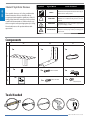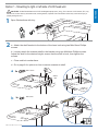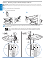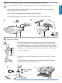
1
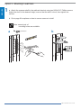
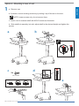
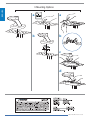
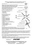
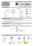
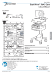
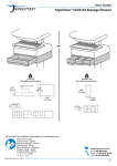
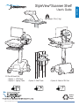
StyleView®Scanner Shelf
Max weight: 2 lbs (1 kg)
SV Cart & Head Unit
• Option 1 - LCD Carts
• Option 2 - Laptop Carts
3
• Option 3 - Wall Track
6
• Option 4 - Back of SV Cart
7
Reduce
Reuse
Recycle
888-97-319-W-01 rev. C • 07/13
1 of 8
ENGLISH
User's Guide
ENGLISH
Hazard Symbols Review
Symbol
These symbols alert users of a safety condition that
demands attention. All users should be able to
recognize and understand the significance of the following Safety Hazards if encountered on the product
or within the documentation. Children who are not
able to recognize and respond appropriately to Safety
Alerts should not use this product without adult
supervision!
Signal Word
Level of Hazard
NOTE
A NOTE indicates important information that helps you
make better use of this product.
CAUTION
A CAUTION indicates either potential damage to
hardware or loss of data and tells you how to avoid the
problem.
WARNING
A WARNING indicates either potential for property damage, personal injury, or death.
ELECTRICAL
An Electrical indicates an impending electrical hazard
which, if not avoided, may result in personal injury, fire
and/or death.
Components
A
1x
B
C
1x
1x
1
2
3
1x
M4 x 16mm
2x
1x
1x
M5 x 12mm
2x
2x
#8/32x5/16”
Tools Needed
14mm
1/4”
888-97-319-W-01 rev. C • 07/13
2 of 8
Option 1 - Mounting to right or left side of LCD head unit
1
2
Open Worksurface with key.
a. Attach the shelf bracket to the bottom of the head unit using two M4x16mm Phillips
screws.
b. Loosely attach the scanner shelf to the bracket using two M4x8mm Phillips screws.
Adjust the shelf to the desired height; ensure that the shelf is level, then tighten the
screws.
c. Close and lock worksurface.
d. Go to page 8 for options on how to secure scanner to shelf.
a
2x
M4 x 16mm
exterior
view
b
2x
interior
view
M4 x 8mm
8
888-97-319-W-01 rev. C • 07/13
3 of 8
ENGLISH
CAUTION: Do Not Exceed Maximum SV LCD Cart Weight Capacity 35 lbs. (16 kg). This is the sum of LCD monitor, CPU, keyboard/mouse, scanner and any worksurface load, including drawers, if present. Failure to heed this caution may cause serious Injury or
property damage to occur.
ENGLISH
Option 2 - Mounting to right or left side of laptop head unit
CAUTION: Do Not Exceed Maximum SV Laptop Cart Weight Capacity 22 lbs. (10 kg). This is the sum of laptop, keyboard/mouse,
scanner and any worksurface load, including drawers, if present. Failure to heed this caution may result in personal Injury or property damage.
1
a. Unlock both sides of worksurface.
b. Remove worksurface.
a
b
2
a. Attach the shelf bracket to the right or left side of the head unit using two M4x16mm
Phillips screws.
Note: the screws pass into the head unit floor from above, as illustrated. Laptop
support bar may need to be removed temporarily to allow installation of scanner
bracket.
2x
2x
M4 x 16mm
M4 x 16mm
right
exterior
view
floor view
left
exterior
view
floor view
888-97-319-W-01 rev. C • 07/13
4 of 8
Option 2 - Mounting to right or left side of laptop head unit (cont.)
ENGLISH
3
a. Loosely attach the scanner shelf to the bracket using two M4x8mm Phillips screws.
b. Adjust the shelf to the desired height; ensure that the shelf is level, then tighten the
screws. Close and lock worksurface.
c Go to page 8 for options on how to secure scanner to shelf.
d. After the scanner has been secured to shelf, follow Step 4 Adjustment, below.
a
b
2x
M4 x 8mm
8
4 Adjustment Step
Lift – Up and down
Once the scanner has been mounted to the shelf, it is important that
you adjust the lift tension for the additional weight. Test the lift tension
by moving the head unit up and down. If it travels smoothly and easily
through the full range of motion, and does not drift up or sag down from
the place you set it, the tension is good. If not, adjust as directed below:
To change lift tension:
a. Remove cap and turn adjustment nut with a 14mm (9/16”) socket
head.
b. Test lift tension by lifting head unit up and down. When desired lift
tension has been achieved, replace cap.
b
14mm (9/16")
c
NOTE: Adjustment
may require 40 - 60
revolutions.
888-97-319-W-01 rev. C • 07/13
5 of 8
ENGLISH
Option 3 - Mounting to wall track
1
a. Attach the scanner shelf to the walltrack bracket using two 8/32x5/16” Phillips screws.
Adjust the shelf to the desired height; ensure that the shelf is level, then tighten the
screws.
b. Go to page 8 for options on how to secure scanner to shelf.
Note: several pair of
mounting holes are available.
a
2x
8/32x5/16”
b
8
888-97-319-W-01 rev. C • 07/13
6 of 8
Option 4 - Mounting to rear of cart
ENGLISH
1
a. Remove cap.
b. If present, remove existing accessory by sliding it up off the slot in the riser.
NOTE: loosen screws only, do not remove them.
c. Attach t-nut to scanner shelf with M5x12 screws as illustrated.
d. Slide shelf/nut assembly into slot, adjust shelf to the desired height and tighten the
screws.
a
c
b
2x
d
M5 x 12mm
e
888-97-319-W-01 rev. C • 07/13
7 of 8
ENGLISH
3 Mounting Options
a
a
b
b
c
d
888-97-319-W-01 rev. C • 07/13
8 of 8