1
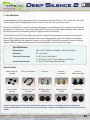
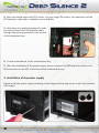
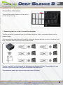
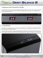
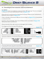
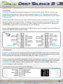
I. Introduction _______________________________________02
• Specifications ____________________________________02
• Accessories ______________________________________02
• Features _________________________________________03
II. Installation Instructions ______________________________06
1. Installation of the motherboard _____________________06
2. Installation of the power supply _____________________07
3. Installation of external drives ________________________08
3.1 Optical drives _________________________________08
3.2 Utilising the external 3.5 inch bay ________________09
4. Installation of hard disk drives ______________________10
5. Removing the front panel __________________________11
6. Fan assembly and cleaning of the dust filters __________11
7. Connecting the fans to the 2-channel fan controller _____14
8. Operation of the 2-channel fan controller _____________15
9. The I/O-Panel ____________________________________15
10. Installation of a water cooling _____________________16
11. Connecting the front connectors with the motherboard__17
11.1 USB 2.0 _____________________________________17
11.2 USB 3.0 _____________________________________18
11.3 HD Audio ___________________________________18
11.4 AC 97 ______________________________________19
III. Support _________________________________________20
01
EN
I. Introduction
Congratulations on the purchase of your new Nanoxia Deep Silence 2 PC tower. We are confident that you will be delighted by your new PC case for many years to come.
Nanoxia’s Deep Silence series have been designed and developed by an experienced team of
developers in Germany. The silent optimised PC cases are of the highest quality and combine
the best possible functionality with the highest level of flexibility.
The Deep Silence 2 PC case offers you plenty of space for hardware and water cooling solutions. Due to the exceptional depth of the case long graphics cards can easily be accommodated. Alternatively, the spacious interior can be used to install for example a water cooling
system (240 mm radiator) between the motherboard and the hard drive cage.
Specifications
Dimensions:
Material:
External drive bays:
Internal drive bays:
468 x 207 x 588 mm (Height x Width x Depth)
0.7 mm Steel
2 x 5.25 inch (tool-free)
1 x 5.25 inch /w 3.5 inch adapter (tool-free)
7 x 3.5/2.5 inch bays (decoupled)
Accessories
Rubber sealings for
tube holes
EPS 4+4-Pin extension
Fan screws
Stand-offs
for mainboard
Screws for
mainboard mounting
Screws for HDD
mounting
Screws for 3,5” mounting frame
Mounting screws for
2.5“HDD/SSD
Mounting screws
for PSU
Thumbscrews
If you are missing any of the items listed above, please contact our customer service immediately:
[email protected] (Germany and Europe); [email protected] (international)
02
Features:
Complete customisable soundproofing with high quality materials meeting industrial
standards
Tool-free mounting of optical drives
Mounting bracket for a 120/240 mm water cooling radiator or up to two 120 mm
fans behind the HDD cage
Max. VGA length 345 mm (up to 370 mm without the Mounting Bracket)
Room for CPU coolers with a maximum height of up to 165 mm
Mounting hole for CPU cooler in the motherboard tray
Cable management with nine rubberized holes in motherboard tray
Nanoxia VentCover (sound proofed) : 2 x top cover, 1 x side panel (left)
2 x USB 3.0, 1 x USB 2.0
2-channel fan control for up to six fans
Noise Insulation
The Nanoxia Deep Silence 2 has been developed with the aim of offer the buyer a low-noise
case, while at the same time allow for extremely low system temperatures. The sound insulation design of the Deep Silence 2 is based on multiple interacting design elements:
The most important part is the large scale lining of the case with sound-absorbing insulation
materials. These materials are manufactured specifically to meet the requirements of the
developers of the Nanoxia Deep Silence case series. The thickness of the material was carefully
selected after extensive testing to ensure the optimum balance between noise suppression
while maintaining acceptable temperatures.
Included are special rubber seals which can be used to alternatively close the tube holes next
to the PCI slot covers and above the rear chassis fan, in case you should not need them.
The removable Nanoxia VentCovers mask the 120/140 mm fan holes in the case top and the
side panel. They allow it to choose between the least possible noise and improved case ventilation. The covers under the top cover are equipped with sound-absorbing foam. The VentCover
in the side panel can be equipped with a self-adhesive bitumen mat. Such a bitumen mat is
included separately to ensure the best compatibility to high CPU coolers.
03
EN
Another design element for optimum sound insulation is a sound-insulated front door. The
door is equipped with sound-absorbing foam and perfectly suited to minimize noise from the
optical drives. The lower part of the case front is also insulated with bitumen to absorb the
noise from the hard disks and the front mounted fans.
The hard disk drives are installed on trays which feature rubber grommets that are designed to
absorb any vibrations caused by the HDDs.
The power supply is isolated from the case by a flexible rubber framework and also rests on
rubber contact points on the bottom of the PSU. This reduces any vibrations caused by the PSU
being transmitted onto the case.
The whole concept of sound proofing of the Deep Silence 2 meets the highest expectations.
Ventilation System
The Nanoxia Deep Silence 2 has an integrated ventilation system consisting of three standard
Deep Silence fans and a built-in 2-channel fan controller for up to six fans. A total of up to nine
fans can be mounted.
To assist the ventilation of the system and in particular of the hard disk drives, a special Mounting Bracket for two 120mm fans is located internally on the HDD cage. This bracket is perfect
to be fitted with a 120 mm or 240 mm radiator or two 120 mm fans.
The Deep Silence 2 axial flow fans have been specifically optimized for very quiet operation.
Both the fan frame and impeller were developed and optimized in extensive trials in a wind
tunnel. In addition to be remarkably low noise, the Nanoxia fans also provide an excellent combination of rotation speed and air flow. The high-quality rifle bearing guarantees a particularly
long service life of up to 80,000 hours.
The range of fan speeds and controls was designed to enable the user to adjust the case ventilation to his own needs.
Front and bottom are equipped with easy to clean dust filters.
04
Standard Equipment:
Front:
Rear:
2 x 120 mm Nanoxia DS-fans (max. 1,300 RPM)
1 x 120 mm Nanoxia DS-fan (max. 1,300 RPM)
Optional Equipment:
Front:
Side:
Bottom:
Top:
2 x 120 mm fan (Mounting Bracket on the HDD-cage)
1 x 140/120 mm fan
1 x 120/140 mm fan
2 x 120/140 mm fans
Watercooling-ready
The Nanoxia Deep Silence 2 can be configured for use of water cooling systems. The mounting bracket between motherboard and hard drive cage is designed to make optimal use of
the above-average depth of the Nanoxia Deep Silence 2 case for water cooling systems. The
bracket can be used to install a 120/240 mm radiator. If necessary, the radiator can then even
be equipped with fans on both sides. Due to the generous proportions of the case, spacing
problems are of no concern.
If you want to mount a compact water cooling system on the mounting bracket, you should
check before the installation whether the factory hoses between cooler and radiator are of
sufficient length.
Rubber hose guides:
The Deep Silence 2 offers four rubber hose guides, so that the appropriate water cooling components can be operated or mounted externally.
On the next pages you can find some useful tips and explanations for the optimal use of your
new case and for the installation of your hardware.
05
EN
Installation Instructions
1. Installing the Motherboard
In order to ensure an easy installation of your motherboard, we suggest the following
procedure:
1. Please consult the following charts to find your motherboard form factor:
E-ATX Mainboard
ATX Mainboard
Micro-ATX Mainboard
Mini-ITX Mainboard
2. Attach the spacers according to your
motherboard form factor.
3. Attach the included EPS extension cable
on to your motherboard – do not connect it
to the power supply yet.
06
4. Next you should mount the CPU cooler - for very large CPU coolers, the attachment of the
EPS extension cable after installation can be difficult.
5. Now place the motherboard gently inside
the case and lead the EPS extension cable
through the opening provided in the top left
of the mainboard tray.
6. Fix the motherboard to the motherboard tray
7. After the installation of the power supply, you can connect the EPS extension cable to the
EPS-connector on the PSU at the back of the motherboard-tray.
2. Installation of the power supply
Please install the power supply according to the diagram below and secure it with the included
PSU screws.
07
EN
3. Installation of external drives
3.1 Optical drives
To install the optical drives, please remove both side panels. The installation of optical drives is
tool-free.
Then loosen the lock on both sides by dragging the black slider backwards (1).
Then slide the drive into the desired position.
Lock the holder by pushing the slider back
to its original position (2).
Remove the 5.25 inch cover by pulling the
lateral tilting lever cautiously towards you
and take out the cover.
Then slide the drive into the desired position. Lock the holder by pushing the slider back to its
original position.
Please note that the two lower shafts are equipped with steel panels, which you have to
remove when you want to use the lower drive bays. To do this, move the steel panels gently
back and forth until you can remove them.
08
3.2 Utilizing the external 3.5 inch bay
If you for example desire to place a 3.5 inch card reader, you can use the internal adapter for
this purpose.
Before you take out the internal adapter,
please remove the 3.5 inch steel cover as
shown on the picture.
Open the two quick release locks of the 5.25 inch bay and remove the mounting frame. Then
attach the card reader in the frame, as shown below.
Then place the frame with the card reader back into the slot and lock the quick release.
Finally, attach the included 3.5 inch adapter to the front cover over the card reader.
09
EN
4. Installation of hard drives
Install the 2.5 or 3.5 inch hard drives in the illustrated mounting frames. In order to extract the
frame, squeeze the protruding brackets and pull the slide out gently.
To install a hard drive into a bracket insert the disk so that the connectors point to the back and
attach the hard drive using the screws provided.
For the fitting of 3.5 inch hard drives please use the holes in Figure 4A (marked red).
For the fitting of 2.5 inch hard drives please use the holes in Figure 4B (marked red).
figure 4A
figure 4B
The hard drives slides offer a second pair of mounting holes, so it is possible to shift the position of the drives. Those are marked in blue on the picture.
To lock the drive, push the bracket with the
drive back installed back into the slot until
the bracket is re-engaged.
10
5. Removing the front panel
To remove the front panel, simply hold the
cutout at the bottom of the front panel and
pull it towards you with a firm tug.
If you remove the front, please note the
I / O panel cables at the top of the front.
Please be cautious here.
6. Fan assembly and cleaning of the dust filters
The air intake openings in the front and at the bottom of the Deep Silence 2 are equipped with
easy to clean dust filters. We recommend that you clean them on a regular basis.
To clean the dust filter is usually sufficient to vacuum these carefully with a vacuum cleaner
(low level).
To switch the fans in the front or to clean the dust filters, please remove the front panel first.
Next, remove the four screws with which the dust filter is connected to the front and take it
out.
Please be advised that the fans are screwed to the dust filter.
The front dust filter allows the installation of either 2 x 120 mm or 1 x 140 mm fans. Two
120mm Deep Silence fans ( approx. 1,300 rpm) are preinstalled.
11
EN
Optional case fans:
Note: Additional case fans in the side panel and the bottom of the Deep Silence 2 should be
mounted so that cooler air is introduced into the case. If you install case fans in the mounting
bracket, those should support the movement of air from front to back.
Case fans installed at the top of the case should exhaust air out of the case.
We recommend the use of the 120 or 140 mm Nanoxia Deep Silence fans, available separately.
These are technically and visually equivalent to the factory-installed case fans and will work in
perfect harmony with the built-in fan control of your case.
Additional fans in the mounting bracket behind the HDD cage:
If you want to mount additional fans inside the case, for example to optimize disk ventilation,
you can use the specially developed mounting bracket that is screwed to the hard drive cage.
Please first remove the screws, as shown on picture 6C.
picture 6C
picture 6D
On the back of the disk cage the frame is
only hooked - here it is sufficient to loosen
the screws slightly (picture 6D).
Hold the fan from the inside to the bracket
and screw it in from the outside. Then hook
the mounting bracket with the fans back in
the cage and attach it with the three screws.
12
Additional fans in the top cover:
If you want to install more fans at the top of
the case, please remove the Nanoxia VentCover first by unscrewing the screws on the
outside of the case.
Then hold the fan from the inside and secure it to the top by fastening the screws from
the outside.
Additional fan in the side panel:
If you want to accommodate a fan in the
side panel, please remove the Nanoxia VentCover first by unscrewing the screws on the
outside of the case.
Please place the fan on the inside of the side
panel and screw it in from the outside.
Additional fan at the case bottom:
If you want to install a 120 or 140 mm fan
on the bottom of the case, please note that
you need to remove the dust filter.
Pull it out just as far as you can easily reach
the screw holes.
13
EN
The dust filter at the bottom:
The dust filter at the bottom can be pulled
out for easy cleaning.
7. Connecting the fans to the 2-channel fan controller
The fan controller is powered by a 4-pin Molex connector that is connected directly to the
power supply.
The controller has two channels (A and B), with each channel able to control up to three 3-pin
fans, therefore a total of six fans can be controlled.
The fan controller is not designed for the operation of powerful fans. Please take this into
account in particular when using fans from other manufacturers.
The maximum power per channel must not exceed 18 watts.
14
8. Operation of the 2-channel fan controller
The sliders of the fan control can be found behind the upper front door. The left slider operates
the fans of the first channel (A1, A2 and A3); the right slider controls the fans of the second
channel (B1, B2 and B3).
9. The I/O-Panel
The I/O panel includes connectors for external USB devices (2 x USB 3.0, 1 x USB 2.0), and the
microphone and headphone ports.
The blue USB connectors are high-Speed USB 3.0; the USB 2.0 port is black. The left audio connector (when viewed from the front) is for headphones, the right is intended for a microphone.
15
EN
10. Installation of a water cooling
The Nanoxia Deep Silence 2 is equipped with a special mounting bracket that is ideally prepared to receive a 120/240 mm radiator. It makes it possible to mount a radiator and can be
equipped with up to four fans for maximum heat-dissipation. Including the pre-assembled 2
x 120 mm Nanoxia Deep Silence fans behind the front panel, up to 6 fans provide a superior
cooling performance.
In order to fix a radiator on the Mounting Bracket, you need to remove the mounting bracket
as described in Chapter 6 (Fan assembly and cleaning the dust filters).
Next, set the radiator you to install flat on the table. Position the mounting bracket with the
outside on the radiator as seen in the picture below.
Put one or two 120 mm fans into the Mounting Bracket and connect fans, bracket and radiator
with extra-long screws.
For maximum cooling capacity of your radiator, you can then mount up to two additional 120
mm fans on top of the radiator.
Radiator with
2 fans
mounted
Radiator with
4 fans
mounted
16
11. Connecting the front connectors with the motherboard
11.1 USB 2.0
Diagram 11 A shows the standard pin assignment of the USB cable plug. The pins are assigned
in a way to fit on current motherboards as shown in diagram 11B.
Please refer to the motherboard and check that the internal USB port of your motherboard is
identical to the one shown in diagram 11A.
If the pin allocation of the internal USB port is the one shown in diagram 11A it is then possible
to connect the cable.
If, however, the pin allocation of the internal USB port and the one shown in diagram 13A
differ, please consult a professional.
Wrong connected cables might cause serious damage to your hardware.
Pin assignment of the front panel USB cable plug.
diagram 11A
Typical pin assignment of an internal USB port on a current market motherboard diagram 11B
Connecting USB cables plug with internal USB port of the motherboard
17
diagram 11C
EN
11.2 USB 3.0
Diagram 11D shows the typical pin assignment of the internal 19-Pin USB 3.0. The pins are
assigned in a way to fit on a current motherboards (diagram 11E). Referring to the motherboard manual, please check that the internal 19-pin USB 3.0 port is identical to the one shown
in diagram 11E.
If the pin allocation of the internal 19-Pin USB 3.0 plug and the one shown in diagram 11E are
the same, please connect the cable. If, however, the pin allocation of the internal 19-Pin USB
3.0 plug and the one shown in diagram 11E differ, please consult a professional. Wrong connected cables might cause serious damage to your hardware.
If your motherboard does not have internal USB 3.0 port, you can acquire an internal 19-pin to
external 2x USB 3.0 Type A adapter cable.
diagram 11D
diagram 11E
11.3 HD Audio
Diagram 11F shows the pin assignment of the standard HD audio cable plug. The pins are assigned in a way to fit on a current motherboards. Referring to the motherboard manual, please
check that the HD audio port is identical to the one shown in diagram 11F.
If the pin allocation of the HD audio plug and the one shown in diagram 11F are the same, please connect the cable. If, however, the pin allocation of the HD audio plug and the one shown
in diagram 11F differ, please consult a professional. Wrong connected cables might cause
serious damage to your hardware.
Pin allocation of the internal HD Audio cable plug
diagram 11F
18
11.4 AC 97
Diagram 11G shows the standard pin assignment of the AC 97 cable plug. The pins are assigned in a way to fit on a current motherboards as shown in diagram 11H.
Referring to your motherboard manual, please check if that the AC 97 port is identical to the
typical shown in diagram 11H.
If the pin allocation of the AC 97 plug and the one shown in diagram 11H are the same, please
connect the cable.
If, however, the pin allocation of the AC 97 plug and the one shown in diagram 11H differ,
please consult a professional. Wrong connected cables might cause serious damage to your
hardware.
Pin assignment of the front panel AC 97 cable plug
diagram 11G
Typical pin assignment of an AC 97 port on a current market motherboard
diagram 11H
19
EN
III. Support
Dear customer,
The PC case you purchased has undergone a very thorough quality control. Nevertheless,
should there be any unexpected problems with your case we ask that you first approach the
dealer where you purchased the product. They are prepared to assist you with competent and
uncomplicated advice and practical support.
If perhaps a few screws were missing or you might have a question that can’t be answered by
this manual, please do not hesitate to contact us directly by e-mail. Likewise, we would appreciate your suggestions and comments about our case very much. Our staff will respond to all
inquiries quickly and professionally.
Customers from Germany and the European countries can use the following e-mail address for
support questions, spare parts or warranty issues:
[email protected]
Customers from Africa, Asia, Australia as well as North and South America can use the following e-mail address for support questions, spare parts or warranty issues:
[email protected]
For general inquiries, comments, suggestions and the like please refer to:
[email protected]
We are sure that you will be satisfied with Nanoxia Deep Silence 2 for many years to come, so
please enjoy your new PC case.
Your Nanoxia Support-Team
20