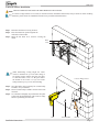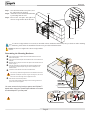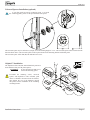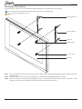
1
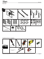
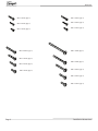
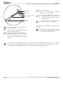
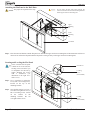
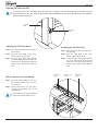
PFW 6851
Display Wall Mount, Turn & Tilt 80 kg
INSTALLATION INSTRUCTIONS
9531-007-Z00-01
PFW 6851
Table of Contents
Warning Statements2
Parts List3
Installation Tools3
Wood Stud Installation5
Concrete Surface Installation7
Determining the Mounting Hardware8
Universal Spacer Installation9
Griplate™ Installation9
Mounting Bracket Installation10
Adapter Plate Installation (optional)11
Attaching the Flat Panel to the Wall12
Securing and Leveling the Flat Panel12
Adjusting the Flat Panel Tilt13
Plastic Channel Cover Installation13
Technical Specifications
14
Warranty15
Warning Statements
PRIOR TO THE INSTALLATION OF THIS PRODUCT, THE INSTALLATION INSTRUCTIONS SHOULD BE READ AND
COMPLETELY UNDERSTOOD. THE INSTALLATION INSTRUCTIONS MUST BE READ TO PREVENT PERSONAL INJURY AND
PROPERTY DAMAGE. KEEP THESE INSTALLATION INSTRUCTIONS IN AN EASILY ACCESSIBLE LOCATION FOR FUTURE
REFERENCE.
VOGEL’S DOES NOT WARRANT AGAINST DAMAGE CAUSED BY THE USE OF ANY VOGEL’S
PRODUCT FOR PURPOSES OTHER THAN THOSE FOR WHICH IT WAS DESIGNED OR DAMAGE CAUSED BY UNAUTHORIZED
ATTACHMENTS OR MODIFICATIONS, AND IS NOT RESPONSIBLE FOR ANY DAMAGES, CLAIMS, DEMANDS, SUITS,
ACTIONS OR CAUSES OF ACTION OF WHATEVER KIND RESULTING FROM, ARISING OUT OF OR IN ANY MANNER
RELATING TO ANY SUCH USE, ATTACHMENTS OR MODIFICATIONS.
THE SURFACE MUST BE CAPABLE OF SUPPORTING AT LEAST FIVE TIMES THE WEIGHT OF THE FLAT PANEL. IF NOT, THE
STRUCTURE MUST BE REINFORCED. THE MAXIMUM WEIGHT THAT CAN BE USED WITH THIS PRODUCT IS 79 KG. PROPER
INSTALLATION PROCEDURE BY A QUALIFIED SERVICE TECHNICIAN, AS OUTLINED IN THE INSTALLATION INSTRUCTIONS,
MUST BE ADHERED TO. FAILURE TO DO SO COULD RESULT IN SERIOUS PERSONAL INJURY, OR EVEN DEATH.
SAFETY MEASURES MUST BE PRACTICED AT ALL TIMES DURING THE ASSEMBLY OF THIS PRODUCT. USE PROPER SAFETY
GEAR AND TOOLS FOR THE ASSEMBLY PROCEDURE TO PREVENT PERSONAL INJURY.
At least two qualified people should perform the assembly procedure. Injury and/or damage can result from dropping or mishandling the flat
panel.
If mounting to studs, make sure that the mounting screws are anchored into the center of the studs. Use of an edge-to-edge stud finder is
recommended.
Be aware of the mounting environment. If drilling and/or cutting into the mounting surface, always make sure that there are no electrical
wires in wall. Cutting/drilling into an electrical line may cause serious injury.
Make sure there are no water lines inside the wall where the mount is to be located. Cutting/drilling into a water line may cause severe water
damage to the mounting surface.
This product is intended for indoor use only. Use of this product outdoors could lead to product failure and personal injury.
Do not install near sources of high heat. Do not install on a structure that is prone to vibration, movement or chance of impact
Page 2
Installation Instructions
PFW 6851
Parts List
Extension Adapter Hardware Pack
Swingout Arm (Qty 1)
5/16” x 3” Lag Bolts (Qty 6)
Thread Depth
Indicator (Qty 1)
5/16” Flat Washers (Qty 6)
Universal
Spacers (Qty 24 )
Extension Adapters (Qty 4)
Universal Mounting Brackets (Qty 2)
Griplate™ (Qty 6)
M8 Nylon Nut
(Qty 4)
5/16” Flat Washers
(Qty 4)
Channel Covers (Qty 6)
Installation Tools (not supplied)
Phillips Screwdriver
1/4” Drill Bit
Electronic Stud Finder
Drill
Level
1/2” Socket and Socket
Wrench
Tape Measure
Installation InstructionsPage 3
PFW 6851
M4 x 30mm (Qty 6)
M5 x 30mm (Qty 6)
M4 x 25mm (Qty 6)
M5 x 25mm (Qty 6)
M4 x 16mm (Qty 6)
M6 x 45mm (Qty 6)
M5 x 16mm (Qty 6)
M8 x 70mm (Qty 4)
M6 x 30mm (Qty 6)
M6 x 25mm (Qty 6)
M6 x 16mm (Qty 6)
M8 x 45mm (Qty 6)
M8 x 30mm (Qty 6)
M8 x 25mm (Qty 6)
M8 x 16mm (Qty 6)
Page 4
Installation Instructions
PFW 6851
Wood Stud Installation
THE FOLLOWING STEPS MUST BE PERFORMED BY TWO PEOPLE.
Wall Stud
Electronic
Stud Finder
Step 2. Once the studs have been located, use a pencil
to mark the center of each stud.
Step 1. Determine the desired viewing location. Use a
stud finder to locate two studs closest to the
viewing location.
Wall Stud
A minimum of two (2) wall studs must be
used in the installation of this product.
Upper Mounting
Channel
Mounting Slot
Flat Washer
1/4” Drill
Bit
5/16” Lag Bolt
1/2” Socket
Wrench
When determining viewing height, the center
of the TV should be at eye level while sitting in
an upright position. When using the flat panel
as room decoration, raise it to the point where
the bottom of the screen is at eye level while
sitting and the top is eye level when standing.
Step 3. Drill a pilot hole at the marked location using a
power drill and a 1/4” drill bit.
Only use 1/4” drill bit when drilling the
pilot holes.
Two people must perform the installation. One
person must hold the mount while the other person
levels the mount. The mount must remain in place
while the mounting hardware is tightened.
Step 4.
Step 5.
Step 6.
Level the mount.
Align the mounting slot with the drilled hole.
Insert and tighten one (1) 5/16” x 3” lag bolt and
flat washer. Tighten using a 1/2” socket
wrench. Do not completely tighten the lag bolt
at this time.
Do NOT over-tighten lag bolts when
attaching the mount to the wall. Improper
installation may result in personal injury or
damage to property.
Installation InstructionsPage 5
PFW 6851
Mounting Slot
Flat Washer
Step 10.Re-level the PFW 6851.
Step 11.Using a 1/2” socket wrench, completely
tighten the two (2) upper lag bolts.
Do NOT over-tighten lag bolts when
attaching the mount to the wall. Improper
installation may result in personal injury or
damage to property.
Upper Mounting Channel
5/16” Lag Bolt
1/2” Socket
Wrench
Before drilling the second mounting hole,
re-level the mount.
Step 7.
Step 8.
Step 9.
Drill a pilot hole at the marked location using a
power drill and a 1/4” drill bit.
Align the mounting slot with the drilled hole.
Insert and tighten one (1) 5/16” x 3” lag bolt and
flat washer. Tighten using a 1/2” socket
wrench. Do not completely tighten the lag bolt
at this time.
A minimum of two (2) wall studs must be
used in the installation of this product.
Repeat these steps to secure the lower mounting channel
to the wall.
There will be a total of four (4) mounting
points (2 for the upper mounting channel and
2 for the lower mounting channel).
If the studs are 12” (304.8mm) apart, use three 3” (76.2mm) lag bolts for the upper mounting channel and three 3” (76.2mm)
lag bolts for the lower mounting channel. If the studs are 16”(406.4mm), 18” (457.2mm) or 24”(609.6mm) apart, use two 3”
lag bolts for the upper mounting channel and two 3” lag bolts for the lower mounting channel.
Page 6
Installation Instructions
PFW 6851
Concrete Surface Installation
THE FOLLOWING STEPS MUST BE PERFORMED BY TWO PEOPLE.
If concrete wedge anchors are not used (as described in these installation instructions) and you decide on other mounting
hardware, please follow the installation instructions as provided with that hardware.
Step 1. Determine the desired viewing location.
Step 2. Place the mount into position against the
wall and level the mount.
Step 3. Mark off four holes to be used for securing the
mount.
Mark
Level
When determining viewing height, the center
of the TV should be at eye level while sitting in
an upright position. When using the flat panel
as room decoration, raise it to the point where
the bottom of the screen is at eye level while
sitting and the top is eye level when standing.
Step 4.
Step 5.
Step 6.
Concrete Wedge Anchor
Next, drill holes using a masonry bit (commercially
available) for your anchors.
Insert a commercially available concrete anchor into
each hole.
Use a hammer and lightly tap each anchor into place
so that only the threaded shaft of the concrete wedge
anchor is protruding from the wall.
Drill
Threaded Shaft
Hammer
Installation InstructionsPage 7
PFW 6851
Step 7. Once all of the anchors are in place, move
the wall bracket into position.
Step 8. Attach the nut onto the threaded shaft that
is protruding from the wall.
Step 9. Re-level the wall plate and tighten all
concrete wedge anchor nuts at this time.
Level
Threaded
Shaft
Nut
1/2” Socket
If concrete wedge anchors are not used (as described in these installation instructions) and you decide on other mounting
hardware, please follow the installation instructions as provided with that hardware.
Do NOT over-tighten the concrete wedge anchors.
Determining the Mounting Hardware
Insert a small straw or toothpick into the threaded inserts found on the
nn
back of the flat panel.
Use a pencil to mark the depth of the threaded insert on the small straw or
oo
toothpick.
Mark the straw or toothpick 1/8” above the depth of the threaded insert, as
pp
shown in Figure 1.
Insert the small straw or toothpick into the remaining threaded inserts
qq
to compare and verify their depth using the straw or toothpick’s 1/8”
allowance mark.
Locate the correct diameter screw for the threaded insert.
rr
If the screw you selected is longer than the 1/8” allowance mark on the
small straw or toothpick, as shown in Figure 2 and Figure 3, do not use
this screw. The screw length must not bypass the mark.
Test each size of the screws provided.
ss
Marking the 1/8”
Allowance
The correct screws should thread easily into the mounting point and not
pull out when tension is applied.
You must account for the bracket, spacers and Griplate™
depths when using the Thread Depth Indicator to measure
the thread depth of your flat panel.
Small Straw or Toothpick
Small Straw
or Toothpick
Depth Plus 1/8” Allowance
Mark
Small Straw
or Toothpick
Depth Plus 1/8” Allowance
Mark
Page 8
PFW 6851
Universal Spacers Installation (optional)
If your flat panel has uneven mounting points, or recessed
mounting points, please use the provided universal spacers.
The universal spacer may be stacked six (6) high, for a total stacking height of 1-1/2”. The universal spacers must be stacked in the
direction shown above. The universal spacers must be placed between the mounting bracket and the flat panel.
The universal spacer will fit M4, M5, M6 and M8 screws sizes.
Dimples
Griplate™ Installation
M8
M6
M5
M4
The Griplates™ have M4, M5, M6 and M8 hole patterns to
fit the hardware that your flat panel requires.
EXAMPLE:
If your flat panel uses M8 screws,
use the M8 mounting points.
Pre-install the mounting screws, universal
spacers and Griplates™. Once mounted, push
down to eliminate movement from the bracket,
then tighten the rest of the hardware. Repeat
this process for the installation of the remaining
mounting bracket.
DIMPLES
FACING UP
DIMPLES
FACING UP
DIMPLES
FACING DOWN
DIMPLES
FACING DOWN
Installation InstructionsPage 9
PFW 6851
Mounting Bracket Installation
This kit provides a variety of screws with different lengths and diameters to accommodate most flat panels.
The number and location of mounting points will vary between manufacturers.
Do NOT over-tighten the screws.
Mounting Hardware
Mounting Bracket
Griplate™
Mounting Point
Universal Spacer
Flat Panel
Step 1.
Step 2.
Step 3.
Place your flat panel screen down on a soft, flat surface and locate the threaded mounting points that are located on the back
of the flat panel.
Determine which screw is the correct length (please see “Determining the Mounting Hardware” section).
Attach each bracket to the flat panel by aligning the holes on each bracket with the threaded inserts on the back of your
flat panel, insert the screws through both and turn clockwise until they are fully inserted.
Page 10
Installation Instructions
PFW 6851
Adapter Plate Installation (optional)
The adapter plates can be used with mounting patterns from 200mm x 200mm to 650mm x 840mm.
In the event that your flat panel has recessed or an uneven mounting surface, universal spacers may be stacked to achieve
proper spacing. Select the amount of universal spacer (s) that is closest in depth to keep your adapter plate as close to the flat
panel as possible. The universal spacer must be secured between the flat panel and the adapter plates.
Do NOT over-tighten the screws.
Step 1. Determine if your flat panel will need the
adapter plates.
Step 2. Locate the mounting points on the back of the
flat panel.
Step 3. Using a screwdriver, insert and tighten the
mounting hardware and adapter plates to the
back of the flat panel. Do not over-tighten the
screws.
Adapter Plate
Griplate
Mounting
Hardware
Flat Panel
Adapter Plate
Socket Wrench
Step 4. Place the universal mounting brackets over
the threaded mounting studs that are on the
adapter plate.
Step 5. Place one (1) 5/16” flat washer onto each
threaded mounting stud.
Step 6.Thread one (1) M8 nylon nut onto each
threaded mounting stud.
Before tightening the nylon nut, be sure
that both universal mounting brackets are
level and aligned with each other. If they are
not aligned and level, the flat panel will not
sit properly when mounted to the PFW 6851.
Step 7. Once the universal mounting brackets are level,
use a 1/2” socket and socket wrench to tighten
Flat Washer
the M8 nylon nuts. Do not over-tighten the
screws.
Universal Mounting
Nylon Nut
Bracket
Installation InstructionsPage 11
PFW 6851
Attaching the Flat Panel to the Wall Plate
Two people are required for this step.
Do not release the flat panel until verifying the
connection between the universal mounting brackets
and the upper and lower mounting bars.
Upper
Mounting
Bar
Lower
Mounting
Bar
Flat Panel
Step 1. Place the universal brackets and the flat panel over and onto the upper and lower mounting bars of the PFW 6851 and lower it
down. Do not release the flat panel until the flat panel is resting securely on the upper and lower mounting bars.
Securing and Leveling the Flat Panel
In the event that the flat panel
is tilted too far to one side, the
leveling screws will allow you
to compensate for this tilt by
simply adjusting the screws
with a screwdriver (see
illustration to the right for a
clearer view).
Screwdriver
Leveling
Screw
(Pre-installed)
Step 1. Use a screwdriver to adjust the
two (2) M6 x 30 leveling screws,
located on the top of the
mounting brackets.
Step 2.
Once the flat panel is level, use a
screwdriver to tighten the two (2)
M6 x 30 locking screws, located
on
the
bottom
of
the
mounting brackets. Do not
over-tighten these screws.
Page 12
Locking
Screw
(Pre-installed)
Installation Instructions
PFW 6851
Adjusting the Flat Panel Tilt
TO ADJUST THE TILT TENSION OF THE PFW 6851, LOOSEN THE TENSION BOLTS LOCATED ON THE
BOTTOM RIGHT AND LEFT SIDE OF THE MAIN ARM ASSEMBLY. RE-TIGHTEN THESE BOLTS TO ACHIEVE
YOUR DESIRED TENSION.
Tension
Bolt
Tension
Bolt
Adjusting the Flat Panel Down
Adjusting the Flat Panel Up
Step 1. Place one hand at the center top edge of
the flat panel.
Step 2.Place the other hand on the center
bottom edge of the flat panel.
Step 3. Using the upper hand, gently pull the
top of the flat panel away from the wall
while the lower hand gently pushes the
bottom of the flat panel towards the
wall.
Step 1. Place one hand at the center top edge of
the flat panel.
Step 2.Place the other hand on the center
bottom edge of the flat panel.
Step 3. Using the upper hand, gently push the
top of the flat panel towards the wall
while the lower hand gently pulls the
bottom of the flat panel away from the
wall.
Plastic Channel Cover Installation
Side Cover
(Long)
Center Cover
(Short)
Side Cover
(Long)
Step 1. Place the plastic channel covers over
the mounting plate (2 side covers and 1
center cover).
Step 2.Gently push each cover into place,
covering the mounting slots of the
mounting plate.
Repeat steps 1 and 2 for the installation
of the lower plastic channel covers.
Installation InstructionsPage 13
PFW 6851
Technical Specification
All measurements are in inches(mm).
28.18
715.8
30.19
766.8
28.94
735
22.23
564.63
10°
.38
9.5
20.40
518.2
.41
10.3
14.02
356
21.59
548.41
3.11
79
33.21
843.5
(OPEN BACK)
15.90
403.9
(OPEN BACK)
12.52
317.9
16.00
406.4
18.00
457.2
.38
9.53
.41
10.31
25.71
653
26.4
671.2
24.00
609.6
34.31
871.4
Page 14
Installation Instructions