1
Table of Contents
PRODUCT OVERVIEW .................................................................................................................................................................................................................................. 1
PACKAGE CONTENTS................................................................................................................................................................................................................................................................................................. 1
SYSTEM REQUIREMENTS ........................................................................................................................................................................................................................................................................................... 1
INTRODUCTION .......................................................................................................................................................................................................................................................................................................... 1
FEATURES .................................................................................................................................................................................................................................................................................................................... 2
HARDWARE OVERVIEW (IPC1000W) .................................................................................................................................................................................................................................................................... 3
Front View .......................................................................................................................................................................................................................................................................................................... 3
HARDWARE OVERVIEW (IPC1000W) .................................................................................................................................................................................................................................................................... 4
Rear View............................................................................................................................................................................................................................................................................................................ 4
HARDWARE OVERVIEW (IPC1000W) .................................................................................................................................................................................................................................................................... 5
Left Side View .................................................................................................................................................................................................................................................................................................... 5
HARDWARE OVERVIEW (IPC1000WI) ................................................................................................................................................................................................................................................................... 6
Front View .......................................................................................................................................................................................................................................................................................................... 6
HARDWARE OVERVIEW (IPC1000WI) ................................................................................................................................................................................................................................................................... 7
Rear View............................................................................................................................................................................................................................................................................................................ 7
HARDWARE OVERVIEW (IPC1000WI) ................................................................................................................................................................................................................................................................... 8
Left Side View .................................................................................................................................................................................................................................................................................................... 8
INSTALLATION ............................................................................................................................................................................................................................................. 9
HARDWARE INSTALLATION ....................................................................................................................................................................................................................................................................................... 9
WIRELESS INSTALLATION CONSIDERATIONS ....................................................................................................................................................................................................................................................... 10
STARTING THE SETUP WIZARD.............................................................................................................................................................................................................................................................................. 11
Connecting with PPPoE .............................................................................................................................................................................................................................................................................. 18
Connecting with DHCP............................................................................................................................................................................................................................................................................... 25
Connecting with a Fixed IP ....................................................................................................................................................................................................................................................................... 33
CONNECTING THE CAMERA TO YOUR NETWORK USING WPS .......................................................................................................................................................................................................................... 43
CONFIGURATION....................................................................................................................................................................................................................................... 44
USING THE WEB-BASED CONFIGURATION INTERFACE......................................................................................................................................................................................................................................... 44
VIEWING VIDEO ...................................................................................................................................................................................................................................................................................................... 46
VIEWING CAMERA SETTINGS .................................................................................................................................................................................................................................................................................. 48
System............................................................................................................................................................................................................................................................................................................... 49
Video ................................................................................................................................................................................................................................................................................................................. 50
Audio ................................................................................................................................................................................................................................................................................................................. 51
Wireless ............................................................................................................................................................................................................................................................................................................ 52
Network ............................................................................................................................................................................................................................................................................................................ 53
Active Users..................................................................................................................................................................................................................................................................................................... 54
CONFIGURING CAMERA SETTINGS ........................................................................................................................................................................................................................................................................ 55
System............................................................................................................................................................................................................................................................................................................... 56
Video ................................................................................................................................................................................................................................................................................................................. 57
Audio ................................................................................................................................................................................................................................................................................................................. 58
Wireless ............................................................................................................................................................................................................................................................................................................ 59
Network ............................................................................................................................................................................................................................................................................................................ 60
User .................................................................................................................................................................................................................................................................................................................... 61
Date/Time ....................................................................................................................................................................................................................................................................................................... 62
Motion Detection .......................................................................................................................................................................................................................................................................................... 63
Upload .............................................................................................................................................................................................................................................................................................................. 64
E-mail................................................................................................................................................................................................................................................................................................................ 66
Day/Night Mode (IPC1000WI only) ....................................................................................................................................................................................................................................................... 67
TOOLS ......................................................................................................................................................................................................................................................... 68
FTP SERVER TEST ................................................................................................................................................................................................................................................................................................... 68
E-MAIL TEST ............................................................................................................................................................................................................................................................................................................ 69
RESTART ................................................................................................................................................................................................................................................................................................................... 70
FACTORY RESET ...................................................................................................................................................................................................................................................................................................... 71
FIRMWARE UPGRADE ............................................................................................................................................................................................................................................................................................. 72
BACKUP AND RESTORE .......................................................................................................................................................................................................................................................................................... 73
KVIEW SOFTWARE ..................................................................................................................................................................................................................................... 74
LAUNCHING KVIEW FOR THE FIRST TIME ............................................................................................................................................................................................................................................................. 74
ADD A CAMERA FOR MONITORING ....................................................................................................................................................................................................................................................................... 75
KVIEW USER INTERFACE ........................................................................................................................................................................................................................................................................................ 77
Display Controls ............................................................................................................................................................................................................................................................................................ 78
Snapshot, recording and audio controls ............................................................................................................................................................................................................................................... 78
Switch Active Camera Controls ............................................................................................................................................................................................................................................................... 79
Live Video Display Controls ...................................................................................................................................................................................................................................................................... 79
Camera Configuration with KView ........................................................................................................................................................................................................................................................ 80
Launch Web Manager for Selected Camera ....................................................................................................................................................................................................................................... 83
Schedule a recording with Keebox KView ............................................................................................................................................................................................................................................ 83
Create Schedule Templates ....................................................................................................................................................................................................................................................................... 84
Setup Motion Detection with KView ...................................................................................................................................................................................................................................................... 84
Recording Options ........................................................................................................................................................................................................................................................................................ 85
Other Options ................................................................................................................................................................................................................................................................................................ 86
KVIEW PLAYER ........................................................................................................................................................................................................................................... 87
KViewPlayer Interface ................................................................................................................................................................................................................................................................................. 87
Viewing Recorded Videos in KView Player .......................................................................................................................................................................................................................................... 88
USING THE IPC1000W/IPC1000WI WITH A NAT ROUTER ................................................................................................................................................................... 90
TROUBLESHOOTING ................................................................................................................................................................................................................................. 93
TECHNICAL SPECIFICATIONS ................................................................................................................................................................................................................... 95
LIMITED WARRANTY .............................................................................................................................................................................................................................. 104
Product Overview
Product Overview
Package Contents
•
IPC1000W/IPC1000WI KView Wireless N Network Camera/ KView Day/Night Wireless N Network Camera
•
CD-ROM (Utility & User’s Guide)
•
Multi-Language Quick Installation Guide
•
Network Cable
•
Power Adapter
•
Camera Stand
If any of the above items are missing from your package, please contact your reseller.
System Requirements
•
Computer with Microsoft Windows® 7, XP®, Vista®
•
1.3GHz Intel Pentium® 1.3GHz or equivalent AMD Athlon® processor
•
128MB RAM
•
Internet Explorer 6, Firefox 3.5, Safari 4
•
Existing 10/100 Ethernet-based network or 802.11n wireless network
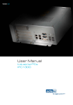
Introduction
Congratulations on your purchase of the Keebox IPC1000W/IPC1000WI KView Wireless N Network Camera. The IPC1000W/IPC1000WI is the perfect
solution for your small office or home monitoring needs. Unlike common webcams, the IPC1000W/IPC1000WI is a complete unit which can operate
without relying on an attached computer as it has its own integrated CPU. Once connected to your network, you can access images or video from
your camera remotely, whether it is through your internal network or over the Internet. The included setup wizard and web-based administration
tool provides a simple and intuitive way to configure and use your network camera over your existing 10/100 Ethernet network or over Wi-Fi using
the built-in 802.11n support.
1
Product Overview
Features
Easy Installation
The IPC1000W/IPC1000WI includes a CD-ROM with a setup wizard that guides you through the process of installation and to get you using your
network camera within minutes.
Wide Platform Support
Supporting TCP/IP networking, HTTP, and other Internet related protocols. The IPC1000W/IPC1000WI can also be integrated easily into other
Internet/Intranet applications because of its standards-based features.
802.11n and 10/100 Ethernet Support
The IPC1000W/IPC1000WI supports both 802.11n and 10/100 Ethernet giving you the flexibility to choose whether to use it wired or mount it in a
spot where you don’t have an Ethernet port, thereby avoiding the need for ugly cables.
Web Configuration
Once installed, administrators can use a standard web browser to access images and video or configure the camera over an intranet or over the
Internet. This means you can access the camera from anywhere in the world.
Broad Range of Applications
With today’s high-speed Internet connections, many applications for your network camera exist, including industrial and public monitoring of homes,
offices, banks, hospitals, child-care centers and amusement parks.
Day/Night Mode (IPC1000WI Model only)
The IPC1000WI is equipped with LEDs at the front to provide better vision in dark locations or in outdoor locations where the image will be required
at both day and night.
2
Product Overview
Hardware Overview (IPC1000W)
Front View
3
Product Overview
Hardware Overview (IPC1000W)
Rear View
4
Product Overview
Hardware Overview (IPC1000W)
Left Side View
5
Product Overview
Hardware Overview (IPC1000WI)
Front View
6
Product Overview
Hardware Overview (IPC1000WI)
Rear View
7
Product Overview
Hardware Overview (IPC1000WI)
Left Side View
8
Installation – Hardware Installation
Installation
Hardware Installation
Connect the Ethernet Cable
If you intend to use the network camera as a wired device, connect one end of the included Ethernet cable into the Ethernet port on the rear panel
of the camera and connect the other end to an available port on your network. If you prefer to use the camera on a wireless network, see below for
instructions on connecting the power adapter.
Attach the Power Supply
Attach the included power supply to the DC 5V 1.2A receptor on the rear panel of the camera and then connect it to a wall outlet or power strip. A
blue LED will light up above the lens indicating that the camera has power.
9
Installation – Wireless Installation Considerations
Wireless Installation Considerations
The Keebox IPC1000W / IPC1000WI KView Wireless N Network Camera can be connected to your network wirelessly from anywhere within its
operating range. However, keep in mind that there are factors that affect the signal strength and range of your connection. The number of objects
the signal must pass through together with the number of radio frequencies in the area will have an effect on the range. Remember these tips to
maximize the wireless range of your network:
•
Keep the number of walls or ceilings that the signal must pass through to a minimum. Each wall or ceiling that the signal must pass through
will have an adverse affect on the range of your network.
•
Be aware of the direct line between the devices. A wall that is at an angle will mean that signal needs to pass through a greater surface area
than the normal thickness of the wall.
•
Building materials make a difference. Try to position access points, routers and computers so that the signal passes through open doorways
or through drywall. Materials such as glass, metal, steel, walls with insulation, bodies of water such as fish tanks, mirrors, file cabinets, brick
and concrete will degrade your wireless signal.
•
Keep the network camera at least 3-6 feet (1-2 meters) away from other devices which generate radio frequencies.
•
If you are using a 2.4GHz cordless phone or other radio frequency sources such as microwave ovens, your wireless signal may degrade or
drop completely. Try to keep the base station of your cordless phone as far away as possible from the camera as the base station will
transmit a signal even if the phone is not in use.
10
Installation – Setup Wizard
Starting the Setup Wizard
Insert the included CD-ROM into your CD/DVD drive. The Install Wizard program will run automatically.
Note: If the Install Wizard does not run, you may have autorun disabled on your machine. In this case, browse to the CD drive and run
InstallWizard.exe to begin the installation wizard.
Begin by selecting Setup Wizard and follow the on-screen steps to continue the installation.
11
Installation – Setup Wizard
When the installation of the Setup Wizard is complete, run the Setup Wizard:
1. Click Start > Programs > KEEBOX > SetupWizard > SetupWizard. The KEEBOX Setup Wizard appears.
2. Connect an RJ-45 cable from a switch/router to the Ethernet port on the back of the camera and connect the AC power adapter to the
camera. Click the > icon to proceed.
12
Installation – Setup Wizard
3. From the list of cameras that appears, select the camera you wish to configure and click the > icon to continue. If your camera is not listed,
ensure that it is connected to both power and the network and click
to re-scan the network for your camera.
13
Installation – Setup Wizard
4. Login to your camera by entering the ID and Password. By default, both the ID and Password are set to admin. Select the > icon to continue.
14
Installation – Setup Wizard
5. Enter a name for the camera in the Camera Name field. The name will be used to identify your camera on the network. Enter the correct
time for the camera for the time zone it is in. If your camera is in the same time zone as the computer you are using, click the
icon to
copy the local time to the camera. Click the > icon to continue.
15
Installation – Setup Wizard
6. It is strongly recommended that you change your password to secure the camera from being accessed by others. Check the Change
Password box and enter the new password in both password fields to confirm the new password. Click the > icon to continue.
16
Installation – Setup Wizard
7. Select a connection option:
PPPoE: Select this option if your camera is directly connected to a DSL modem and your ISP requires a PPPoE authentication to the Internet.
Continue on page 18 if you select this option.
DHCP: Select this option if your camera is connected to a router and DHCP is enabled. Continue on page 25 if you select this option.
Fixed IP: Select this option if your camera is directly connected to a DSL modem and your ISP has supplied you with a fixed IP for your
Internet connection. Continue on page 33 if you select this option.
Select the radio button for your connection type and click the > icon to continue.
17
Installation – Setup Wizzard – Connectin
ng with PPPoE
Connecting with PPPo
oE
Select th
he PPPoE radio button and clicck the > icon to continue.
Enter yo
our PPPoE User Name and Passsword and re-e
enter the password in the Conffirm Password field.
18
Installation – Setup Wizard – Connecting with PPPoE
Select whether you want to use the camera over an 802.11n wireless connection or on a wired connection. Click the > icon to continue.
19
Installation – Setup Wizard – Connecting with PPPoE
Wireless Connection
•
Find the access point (AP) you wish to connect to from the Available AP drop down menu. If the AP you want to connect to is not listed,
click the
icon to re-scan for nearby APs.
•
Select the Wireless Mode, either Infrastructure or Adhoc.
•
In most cases you should leave the Channel set to Auto as the AP will determine the channel of operation.
•
Select the type of authentication and encryption required by the access point and enter the Key required to connect.
Click the > icon to continue.
20
Installation – Setup Wizzard – Connectin
ng with PPPoE
A summ
mary screen of th
he settings you have chosen ap
ppears. Click the > icon to continue.
21
Installation – Setup Wizard – Connecting with PPPoE
After the Setup Wizard configures the camera, a screen prompting you for the connection method appears.
Check the radio button for the method of connection you want to use for your camera and click > to continue.
22
Installation – Setup Wizard – Connecting with PPPoE
Connecting over wireless
Disconnect the Ethernet cable from the camera and wait for 1 minute for the camera to turn to wireless mode then click the > icon to continue.
23
Installation – Setup Wizzard – Connectin
ng with PPPoE
When th
he Setup Wizard
d has finished, th
he configuration
n is complete an
nd the following
g screen appearrs:
You are now ready to begin
b
using yourr camera.
24
Installation – Setup Wizard – Connecting with DHCP
Connecting with DHCP
Select the DHCP radio button and click the > icon to continue.
Select whether you want to use the camera over an 802.11n wireless connection or on a wired connection. Click the > icon to continue.
25
Installation – Setup Wizard – Connecting with DHCP
Wireless Connection
•
Find the access point (AP) you wish to connect to from the Available AP drop down menu. If the AP you want to connect to is not listed,
click the
icon to re-scan for nearby APs.
•
Select the Wireless Mode, either Infrastructure or Adhoc.
•
In most cases you should leave the Channel set to Auto as the AP will determine the channel of operation.
•
Select the type of authentication and encryption required by the access point and enter the Key required to connect.
Click the > icon to continue.
26
Installation – Setup Wizard – Connecting with DHCP
A summary screen of the settings you have chosen appears. Click the > icon to continue.
27
Installation – Setup Wizard – Connecting with DHCP
After the Setup Wizard configures the camera, a screen prompting you for the connection method appears.
Check the radio button for the method of connection you want to use for your camera and click > to continue.
28
Installation – Setup Wizard – Connecting with DHCP
Connecting over wireless
Disconnect the Ethernet cable from the camera and wait for 1 minute for the camera to turn to wireless mode then click the > icon to continue.
29
Installation – Setup Wizard – Connecting with DHCP
When the Setup Wizard has finished, the configuration is complete and the following screen appears:
You are now ready to begin using your camera.
30
Installation – Setup Wizard – Connecting with DHCP
Connecting over a wired network
Confirm that the settings are correct. If they are correct, click the > icon to continue, otherwise click < and make revisions to your settings.
31
Installation – Setup Wizard – Connecting with DHCP
When you confirm your settings are correct, the following screen appears:
You are now ready to begin using your camera
32
Installation – Setup Wizard – Connecting with a Fixed IP
Connecting with a Fixed IP
Select the Fixed IP radio button and click the > icon to continue.
33
Installation – Setup Wizard – Connecting with a Fixed IP
The Network Configuration screen appears. Enter the desired IP Address, Subnet Mask, Default Gateway, Primary and Secondary DNS Servers and
click the > icon to continue. If you do not know the details, you can try clicking
to allow the software to automatically detect the settings.
34
Installation – Setup Wizard – Connecting with a Fixed IP
Select whether you want to use the camera over an 802.11n wireless connection or on a wired connection. Click the > icon to continue.
35
Installation – Setup Wizard – Connecting with a Fixed IP
Wireless Connection
•
Find the access point (AP) you wish to connect to from the Available AP drop down menu. If the AP you want to connect to is not listed,
click the
icon to re-scan for nearby APs.
•
Select the Wireless Mode, either Infrastructure or Ad-hoc.
•
In most cases you should leave the Channel set to Auto as the AP will determine the channel of operation.
•
Select the type of authentication and encryption required by the access point and enter the Key required to connect.
Click the > icon to continue.
36
Installation – Setup Wizard – Connecting with a Fixed IP
A summary screen of the settings you have chosen appears. Click the > icon to continue.
After the Setup Wizard configures the camera, a screen prompting you for the connection method appears.
37
Installation – Setup Wizard – Connecting with a Fixed IP
Check the radio button for the method of connection you want to use for your camera and click > to continue.
38
Installation – Setup Wizard – Connecting with a Fixed IP
Disconnect the Ethernet cable from the camera and wait for 1 minute for the camera to turn to wireless mode then click the > icon to continue.
39
Installation – Setup Wizard – Connecting with a Fixed IP
After a moment, the configuration is complete and the following screen appears:
You are now ready to begin using your camera.
40
Installation – Setup Wizard – Connecting with a Fixed IP
Connecting over a wired network
Confirm that the settings are correct. If they are correct, click the > icon to continue, otherwise click < and make revisions to your settings.
41
Installation – Setup Wizard – Connecting with a Fixed IP
When you confirm your settings are correct, the following screen appears:
You are now ready to begin using your camera.
42
Installation – Connecting the camera to your network using WPS
Connecting the camera to your network using WPS
An alternative method of connecting your camera to your network is by using WPS. WPS is a quick, simple and secure method of adding devices to
a network. If you have a router which supports WPS follow the steps below, otherwise, please use the wired mode of setting up the camera.
Note: Please complete the following steps within 2 minutes.
1. Press the WPS button on your wireless device to activate the function.
2. Press the WPS button of your wireless network camera for at least 5 seconds. The WPS light will start to blink green. Within 2 minutes, the
WPS light will either show a solid green light indicating that the connection was successful or the light will stop flashing and will not be
illuminated. If the light is not illuminated after 2 minutes, the connection was unsuccessful. Try repositioning the camera or router and try the
WPS connection again.
43
KView Software
Configuration
Using the web-based configuration interface
After completing the Setup Wizard, you are ready to use your camera. The camera’s built-in Web configuration utility is designed to allow you to
easily access and configure your IPC1000W/IPC1000WI camera. Open a web browser such as Internet Explorer® and enter the IP address of your
camera. To log in, use the User name admin and the password you created in the Setup Wizard. If you did not create a password, the default
password is admin. After entering your password, click OK.
44
Configuration – Using the web-based configuration interface
The home page for the IPC1000W/IPC1000WI appears.
45
Configuration – Using the web-based configuration interface
Viewing Video
Click VIEW VIDEO | ACTIVEX or VIEW VIDEO | JAVA to begin viewing live video from your camera.
VIEW VIDEO | JAVA
Please make sure that you have the latest version of Java installed on your machine to ensure proper operation when viewing video in Java mode.
The Java application can be downloaded from Sun’s website free of charge (http://www.java.com)
46
Configuration – Using the web-based configuration interface
VIEW VIDEO | ACTIVEX
Windows users who do not have Java installed can choose ActiveX mode to view video. Internet Explorer will prompt you to install ActiveX when you
click on the VIEW VIDEO | ACTIVEX link. Mac users must use the Java mode to view video.
47
Configuration – Using the web-based configuration interface
Viewing camera settings
To view camera settings:
1. Login to the camera as described in the section Using the web-based configuration interface.
2. Click ADMINISTRATION. The system status screen appears.
From the menu on the left side of the screen, select an option under the STATUS heading.
48
Configuration – Using the web-based configuration interface
System
This screen shows the Camera Name, Location, Model, Firmware Version, MAC Address, IP Address, Ethernet Link Status, Speed and Duplex type.
49
Configuration – Using the web-based configuration interface
Video
This screen shows the details of the video capture settings including Video Resolution, Compression Rate, Frame Rate, Frame Size and Light
Frequency.
50
Configuration – Using the web-based configuration interface
Audio
This screen shows whether audio is enabled and the volume level of the audio.
51
Configuration – Using the web-based configuration interface
Wireless
This screen shows the connection mode, link status, SSID name, channel and encryption status.
52
Configuration – Using the web-based configuration interface
Network
This screen shows various network statistics related to your camera including IP Address, Subnet Mask and Default Gateway.
53
Configuration – Using the web-based configuration interface
Active Users
This screen shows whether there are any active users logged on to the camera viewing live video.
54
Configuration – Using the web-based configuration interface
Configuring camera settings
The IPC1000W/IPC1000WI allows you to make configuration changes from anywhere by connecting to the camera using a standard web browser.
To configure camera settings:
1. Login to the camera as described in the section Using the web-based configuration interface.
2. Click ADMINISTRATION. The system status screen appears.
3. Click CONFIGURATION from the menu on the left side of the screen. The System configuration screen is displayed. You can then click on
any of the menu items on the left of the screen under the Configuration menu to modify settings.
55
Configuration – Using the web-based configuration interface
System
•
Camera Name: This is the name used to identify your camera on your network.
•
Location: You can enter a description of the place where the camera is.
•
Admin: In this field you can change the administrator user name and password.
•
LED Control: Setting this to Normal will display the lights on the front of the camera indicating power and network activity. Setting this to
OFF will turn off both lights on the front of the camera.
56
Configuration – Using the web-based configuration interface
Video
•
Video Resolution: Select from one of the three resolutions. Higher values provide better quality but at the expense of higher bandwidth
requirements on your network or internet connection.
•
Compression Rate: Select a compression rate. Higher rates of compression will reduce network load at the expense of lower image quality.
•
Frame Rate (Frames/Sec.): Select the number of frames per second you would like for your video. Higher rates provide smoother video but
require more bandwidth on your network or internet connection.
•
Brightness Control: Allows you to control the brightness level. Enter a value between 1 and 128.
•
Contrast Control: Allows you to control the contrast level. Enter a value between 1 and 128.
•
Saturation Control: Allows you to control the saturation level. Enter a value between 1 and 128.
•
Light Frequency: Select the correct frequency (50Hz/60Hz) to reduce the amount of flicker.
•
Mirror: Choose whether to mirror the image horizontally or vertically.
•
Anti-Flicker: Check the box to enable anti-flicker.
57
Configuration – Using the web-based configuration interface
Audio
•
Audio: Choose whether to Enable or Disable the camera audio feed.
•
Volume: Select the volume percentage level.
58
Configuration – Using the web-based configuration interface
Wireless
•
Connection Mode: Infrastructure is a wireless connection using an access point as a transmission point of all wireless devices. Ad-Hoc is a
wireless connection used without an access point, where your IPC1000W/IPC1000WI is directly connected to your PC. This is done using
the on-board wireless adapter on the IPC1000W/IPC1000WI connected to a wireless adapter on the PC.
•
SSID: Service Set Identifier. This is an identifier for your network. Manually enter the SSID of your wireless network or select it from the drop
down menu. You can click Site Survey to see a list of wireless networks within range and further details of their settings.
•
Wireless Channel: When using Infrastructure mode, the channel is specified by the access point and the channel will not be selectable on
this menu. When using Ad-Hoc mode, you can specify on which channel you want to communicate with the camera.
•
Encryption Type: It is highly recommended that you encrypt the connection. In Infrastructure mode, select an encryption type and enter
details where applicable as you have specified on the access point. If you intend to use Ad-Hoc mode, you can specify here the encryption
type and preshared key that you want to use to connect from the PC.
59
Configuration – Using the web-based configuration interface
Network
•
IP Address Mode: Choose a method to assign an IP address to your camera.
o
Fixed IP – If you want to assign a static or fixed IP address to the camera, you may do so here. Your network administrator should be
able to provide you with the necessary details to complete this section.
o
Dynamic IP (DHCP) – Allows a DHCP server to automatically assign the camera a network address.
o
PPPoE – If you are using a PPPoE connection, enter your user name and password here
•
Dynamic IP: Enter the Domain Name Server addresses which translate names to IP addresses.
•
Dynamic DNS: The Dynamic DNS feature
allows you to host a server (e.g. web
server, FTP or Game server) using a
domain that you own with a dynamically
assigned IP address. Many ISPs assign IP
addresses dynamically i.e. the IP address
changes each time you connect and
disconnect. Using a Dynamic DNS service
provider, you can connect to your camera
no matter what your IP address. Enter the
details of your dynamic DNS service
provider here.
•
HTTP Port: You may configure a second
HTTP port that will allow you to connect
to the camera using a standard web
browser. The port can be set to a number
other than the default TCP ports 80. A
corresponding port must be opened on
the router. For example, if the port is
changed to 1010, users must type
“http://192.168.0.100:1010” instead of
only “http://192.168.0.100”.
•
uPnP & uPnP Port Forwarding: Enable these to set your camera as a universal plug n play device on your network.
60
Configuration – Using the web-based configuration interface
User
•
User Access Control: Enable this to allow user accounts to connect to the camera.
•
Define Users: You can create new user accounts here. Enter a user name and password and select whether the user is allowed to upload or
email an image from the camera.
•
Delete User: Select a user from the drop down menu and click the Delete button to remove a user account from the camera.
61
Configuration – Using the web-based configuration interface
Date/Time
•
Synchronized with Time Server: If you have an internet time server or have an NTP server designated on your network, you can specify the
IP address of it here. Ensure that you select the correct time zone for the camera also.
•
Set Manually: If you prefer to manually set the time for the camera, select this mode. You can check the box Synchronized with Computer
Time to set the time on the camera to be the same as the computer you are on.
62
Configuration – Using the web-based configuration interface
Motion Detection
•
Motion Detection: Select whether to Enable or Disable motion detection. This will allow your camera to perform different functions when
activity has been detected in the parts of the screen that you specify.
•
Sensitivity: Set a percentage level to determine how sensitive the camera is to activity.
•
Detection Areas: From the live image shown on this screen, you can left-click on blocks of the grid shown to indicate which parts of the
screen you would like to monitor for motion.
63
Configuration – Using the web-based configuration interface
Upload
On this screen you can enter details of an FTP
Server that you want to upload images from
the camera to.
•
Host Address: The IP address of the
FTP Server
•
Port Number: The port number to
connect to the FTP on. The default is
port 21.
•
User Name: The user name of the FTP
account.
•
Password: The password for the user
account on the FTP.
•
Directory Path: The path you want the
files to be uploaded to on the FTP.
•
Passive Mode: If the camera is behind
a firewall, you might wish to enable
Passive mode to allow the camera to
upload the pictures.
•
Time Schedule: Check Enable upload
image to FTP server to enable the
Upload function.
o
Always: Selecting this option
allows snapshots to be
uploaded to your FTP as soon as you click Save.
o
Schedule: Selecting this option allows you to configure specific times when you want the snapshots to be uploaded to your FTP
server.
o
Motion Detection: Selecting this option sets the camera to upload images upon detection of motion.
o
Manual Operation: Selecting this option means the user is responsible for taking a snapshot from the camera to upload.
64
Configuration – Using the web-based configuration interface
•
Video Frequency: Users can select in frames per second (1, 2, 3 or auto, in auto this could go to 4). The user can also select a duration for
each frame from 1 to 65535 seconds.
•
Base File Name: Enter the prefix for the filename of each snapshot taken by the camera.
•
File: If Overwrite is selected, only a few images will be constantly refreshed, depending on how many snapshots you choose to have sent.
Select Date/Time Suffix and the pictures will be named with a date and time also. Select a Sequence Number Suffix up to 1024 and all the
pictures will be numbered from 1-1024. Up to 1024 pictures can be configured. Picture number 1025 will reset to number 1.
65
Configuration – Using the web-based configuration interface
E-mail
This section allows you to configure the email notification settings of your camera.
•
SMTP Server Address: The
domain name or IP address of
your external mail server
•
SMTP Port Number: The port
number of your mail server,
usually this is port 25.
•
Sender’s Email Address: The
e-mail address of the person
sending the camera snapshots.
•
Recipient’s E-mail Address:
The e-mail address of the
person receiving the camera
snapshots.
•
User Name: The user name of
the sender’s email account for
SMTP authentication.
•
Password: The password of the
sender’s account for SMTP
authentication.
•
Use SSL-TLSS/STARTTLS: If
your mail server supports SSLTLSS or STARTTLS, you can select one of these methods to create an encrypted connection to the mail server.
•
Time Schedule: Check Enable e-mail image to e-mail account to enable the time schedule function.
o
Always: Selecting this option will allow snapshots to be emailed when you click Save.
o
Schedule: Selecting this option allows you to configure specific times when you want the snapshots to be emailed.
o
Motion Detection: Selecting this option sets the camera to e-mail images upon detection of motion.
o
Manual Operation: Selecting this option means the user is responsible for taking a snapshot from the camera to e-mail.
66
Configuration – Using the web-based configuration interface
Day/Night Mode (IPC1000WI only)
The IPC1000WI comes equipped with LEDs to enable the camera to have greater visibility in dark locations. On this screen you can configure when
to set the camera to day mode and night mode.
•
Auto: The camera automatically senses when there is inadequate light and switches to night mode.
•
Manual: The user must manually change between night mode and day mode from the View Video windows.
•
Always Day Mode: The camera will always stay in day mode and never switch to night mode.
•
Always Night Mode: The camera will always stay in night mode and never switch to day mode.
•
Day Mode Schedule: The user can specify a schedule when the camera is in day mode.
67
Configuration – Using the web-based configuration interface
Tools
FTP Server Test
When you have set up the FTP Server in the configuration section, you can use this screen to test that the FTP Server settings are correct. Pressing
the Test button will make a connection to the FTP Server and upload a file called test_date_time.jpg to the FTP. If the file is not there, you should
check that you have entered the FTP details correctly in the configuration section.
68
Configuration – Using the web-based configuration interface
E-mail Test
When you have set up an e-mail account in the configuration section, you can use this screen to test that the E-mail settings are correct. Pressing
the Test button will make the camera send a test e-mail to the address specified in the configuration section. If you do not receive the test e-mail,
you should check that you have entered the e-mail details correctly in the configuration section.
69
Configuration – Using the web-based configuration interface
Restart
If you should need to restart the IP camera, you can do this from this screen. Clicking Yes will initiate a reboot sequence on the camera. When you
restart the camera you will lose your connection to it. Wait 1 minute before attempting to reconnect to the camera so that it has time to go through
its boot up sequence. Restarting the camera will retain the configuration settings you have entered.
70
Configuration – Using the web-based configuration interface
Factory Reset
If you should need to restore the camera to the factory settings, you can do it from this screen. Clicking Yes will initiate a reboot sequence on the
camera. When the camera restarts, you will lose your connection to it. The username and password will also both be set back to the default admin.
Wait 1 minute before attempting to reconnect to the camera so that it has time to go through its boot up sequence.
Note: Factory reset will erase the current configuration settings on the camera. You should back up the settings first if you wish to keep them. See
the Backup and Restore section for more information.
71
Configuration – Using the web-based configuration interface
Firmware Upgrade
Keebox may occasionally provide new firmware on the Keebox website. If you need to update your camera’s firmware you can do it on this screen.
Click the Browse button and locate the firmware file you saved on your computer and choose Open. When you are ready, click the Upgrade button
to begin the firmware upgrade.
Note: Upgrading the firmware is a sensitive process. Be sure that you have the correct firmware for your model of camera and do not disconnect the
power during the upgrade process.
72
Configuration – Using the web-based configuration interface
Backup and Restore
When you have set up the camera and you are satisfied with the settings, you can backup the settings to a file for future reference. If you should
change the settings and want to revert back to the previous settings, you can do so on this page. To backup the configuration, click Backup and
select a location to save the file, then choose Save. To restore settings from a configuration file, click Browse and locate the backup configuration
file on your hard drive then click OK. Click Restore to complete the process.
73
KView Software
KView Software
This section describes the how to setup a camera using the KView camera monitoring software. To install KView on a system running Windows,
launch the KView installation software on the installation CD-ROM and follow the setup instructions. Once the software is installed, the Keebox
KView camera monitoring utility is ready for use. Add up to 32 network cameras to monitor using the software. Additional software, Keebox KView
Player software is also installed. The KView Player is used for playing recorded video from cameras that have been configured to save recorded files.
Launching KView for the
first time
To launch KView, double click on
the KView icon on your desktop
or go to Start > Programs >
KEEBOX > KView > KView. If
this is the first time using the
software, the menu that appears
is the Add camera menu. To add
your IP camera:
•
Search for the IP camera
on the local area network
(click on refresh) or
•
Import
an
existing
configuration file
74
KView Software
Add a camera for monitoring
The Add camera menu is presented the first time the KView software is launched. This menu is used to add cameras to the user interface for
monitoring. After the first time running the software, this menu can be accessed at anytime from the Configuration menus. The Configuration menus
are described in a later section of this chapter. Note that the KView software has automatically detected eligible cameras running on the network.
To add a camera to the KView user interface, follow these instructions:
1. Check the list of cameras detected by the software. If the camera you want to add does not appear on the list, click the Refresh button to
conduct another search. If it still does not appear, check the IP address of the camera and click on the Input the location of camera menu tab
and skip ahead to step 2.1.
Select the camera you
want to add from the
list here.
Enter the
Username and
Password for the
camera here.
75
KView Software
2. Select the camera to add from the list, enter the administrator’s user name (ID) and password, a preview of the live video display will appear.
Click OK, add this camera, a confirmation message informs when the camera is connected and added to the KView monitoring group.
Repeat this procedure for all the cameras being added. Click the Exit button after all the cameras have been added.
If the camera does not appear listed, click the Input the location of camera tab above the list to view a new menu. Enter the IP address or
the URL (for example, ipcam.ddns.org) of the camera being added, type the user name and password and click Preview to verify that a link
can be established. The live video of the camera should appear in the Live preview display. If a link cannot be established, run the Setup
Wizard software for the camera and verify the correct IP address. Click Exit to return to the main Add camera menu.
3. Once the cameras have been added, they are ready to be used in the main KView user interface. Close the Add camera menu (click Exit) to
go to the main user interface. See below for a description.
76
KView Software
KView
w User Interfa
ace
Numb
ber
1
Item
Live Video Disp
play
2
3
4
5
6
7
Minimize and Exit
E
Not used
Snapsshot, record and au
udio controls
Sw
witch Active Camera
a Controls
Live
L
Video Display Controls
C
Camera Configuratio
on Menu
8
9
Camera Informa
ation
Camera Statu
us
Desccription
Display area for single
s
or multiple ca
amera video feeds. You can right clickk on the video displlay area to bring up
pa
context menu allowing you
u to toggle differen
nt functions.
Use
ed to minimize KView or exit the appliication.
Not used for this
t
camera model
Used to take snap
pshots, record video
o and control the microphone
m
on the ccamera. See below for more information.
These co
ontrols are used to cycle through the displayed
d
camera w
when using single viewer
v
mode.
Used to change window display configuration, change
e scan mode, record, playback and sho
ow full screen video
o.
Used to add and remove cameras, change monitoring settings including sschedules and motiion detection, chan
nge
ecording options an
nd other system setttings.
re
Displayss general information about the selectted camera.
Disp
plays the current sta
atus of the added ccameras.
77
KView Software
Display Controls
The primary display and KView control icons are described in detail below. When there are more than one camera displays viewed, one of the
displays can be selected for management or additional changes. Simply left click on any display to select it. Notice the border around the display is
blue, indicating the “selected” status. For example, to go to a single screen display for any one camera, select the camera and click on the 1 Viewer
Mode button.
Snapshot, recording and audio controls
The still photo camera icon is used to take a snapshot of the selected live video display. The video camera icon is used to begin video recording of
the selected live video display. Snapshot and video files are stored in a default folder on the administrator’s system, or in a folder designated by the
administrator under the Camera Configuration Menu > Recording Options tab.
The audio controls are represented by a microphone icon to activate the internal mic or the auxiliary audio input (if present), and a speaker icon for
the audio output (remote speakers, if present).
Notice that when these functions are activated, the color of the icon changes from white to yellow.
Inactive Video and Audio controls
Active Video and Audio controls
78
KView Software
Switch Active Camera Controls
These controls are used to cycle through the displayed camera when using single viewer mode.
Live Video Display Controls
Click multi-screen display icons to change the number of camera’s displayed at one time.
To change the order in which the camera displays appear in the interface, move the cursor over a
display you want to change and right click. A dialog appears (see example below). The top option in
the context menu allows the user to Replace content by … followed by a list of connected camera IP
addresses (or URL locations). Select the camera display you want to occupy the position the cursor
is placed over. The display position will then be swapped with the chosen camera.
79
KView Software
Switch to full screen of the selected display
Click to automatically cycle through the active camera displays.
Click to record all active cameras.
Click to launch the KView Player application to view recorded video files.
Click to add, remove and configure camera options.
Camera Configuration with KView
Access the camera configuration menus by clicking on the gear icon at the bottom of the right hand panel of the KView user interface. Configuration
options include adding and deleting cameras from the display view, configuration of motion detection and digital input with schedules, recording
options, email alerts and other network settings.
Adding a Camera – Camera management
The procedure to add a camera after the initial launch of the software is very similar to the procedure used during the first setup. Follow the
instructions below to add cameras.
80
KView Software
To add a camera:
1. Click the Configuration icon to view the Camera Setup menu. At the top of the Camera management tab, Click the Add Camera by IP/URL.
2. If you know the IP or URL of the camera, enter it in the field on the Input the location of camera tab and then enter the port number. Enter
the username and password on the right side of the screen and click Ok, add this camera. If you do not know the IP address or URL of the
camera, click the Select a camera in LAN tab and select the camera from the list. Enter the username and password for the camera on the
right side of the screen and click Ok, add this camera.
81
KView Software
3. The camera added now appears in the Camera List. To launch the web manager for the newly added camera or any camera in the active
camera list, select it and click the Browse Selected Camera button.
82
KView Software
Removing a Camera
To remove the camera from the list of active:
1. Select the camera you want to remove.
2. Click Delete Selected Camera.
NOTE: Any camera display can be removed from the main KView user interface by right-clicking on the display screen for the camera and selecting
the Remove this Camera option.
Launch Web Manager for Selected Camera
To launch the web-based IP Camera manager for any active camera in the list, simply select it and click the Browse Selected Camera button.
Schedule a recording with Keebox KView
Use the Monitoring Settings menu to create schedules for recording and apply the schedules to any camera. Click the Monitoring Settings tab to
view the Schedule Recording menu (the first menu viewed in the Camera Settings menu tab).
To apply an existing schedule template, click the Enable schedule
recording checkbox then click the Select button and choose a
schedule from the list of previously created schedules by checking its
checkbox and click the OK button. If a new schedule is needed it can
be created by clicking the Select button and then the Edit profiles
button in the Select schedule profiles dialog box.
83
KView Software
Create Schedule Templates
To make a new schedule template, click the Edit Profiles button to view the Edit schedule profiles dialog box. Use this new dialog box to create new
schedules for recording. Try to give the new schedule a unique name that describes when the schedule applies. Click Save when you are done.
Click Edit Profiles to edit or create a new
schedule.
Setup Motion Detection with KView
To setup motion detection on the camera, go to the Monitoring Settings
menu and select the Motion Detection tab. Check Enable motion detection.
The Setup motion detection of the camera window appears.
Select an area of the camera’s view that you would like to monitor for
movement by left-clicking to select the parts of the screen you want to monitor
and enter a sensitivity percentage value.
84
KView Software
Recording Options
The Recording Options configured in KView help to conserve and manage allowed memory storage (disk space) and for video file management.
Recorded files can be limited by time elapsed or by size. Use the Select button to choose an alternative destination for stored video files. Storage
limits can be set for each camera by time elapsed or hard disk space allowed. A limit can also be placed for the system and all cameras used in
KView.
85
KView Software
Other Options
Other options available include Proxy settings, Time interval of scan, Sound alarm settings, E-mail sender settings and System Settings.
86
KView Software
KVie
ew Player
KView Player
P
is installed
d along with the
e monitoring KV
View software ass described earliier. KView Playe
er is designed fo
or playing back recorded
r
videoss.
To Start KView Player cllick Start > Programs > KEEBO
OX > KView > KVIEWPLAYER
K
or launch it from the control p
panel of KView. When
W
it starts, the
t
P
will autom
matically scan yo
our recordings fo
older for any ne
ew recordings. The
T recording fo
older is designatted in the KView
w software as
KView Player
describe
ed previously.
KViewP
Player Interface
e
87
KView Software
Number
1
2
3
4
Item
Files List
Video Display Area
Search and Delete Buttons
Playback Controls
Description
A list of recorded files found in the recording folder appears here. Select a file from here and click
the play button to view the recording.
This area shows the video recording. At the bottom of the video is a progress bar .
Use the search button to scan for more video files and delete to remove a video when you are
done with it.
Basic playback controls. Click the arrow buttons to go to the previous or next video in the list. You
can also adjust the volume and playback speed.
Viewing Recorded Videos in KView Player
To view recorded video files in KView Player, it is first necessary to locate and select the files to be viewed and add them to the list. Click the Search
Files button in the KView Player main interface and a new menu appears.
In the new menu, use the Select Camera pull-down menu to choose the video file folder of the camera to be reviewed. Use the Select Time menu
to narrow the search to a specific time and date. Finally, the Event selection menu is used to further narrow the scope of the file search for videos
triggered by Motion Detection or a Digital Input device. When the search criteria have been defined, click the Search button to place qualified
files in the Search list.
88
KView Software
Choose the files to be added to the view file list by checking the individual files or click the Select All button to check all files in the Search list, click
Add to place the check marked files on the list of files for viewing.
After the files to be viewed have been chosen, click the OK button.
Now that the recorded video files have been selected and placed on the file list, they can be played and reviewed in the KViewPlayer . Use the
standard playback controls to play, pause, slow down or speed up video files. Use the mouse and left click to grab the playback sliding progress
indicator to move back and forth through the video.
89
Using the IPC1000W(I) with a NAT Router
Using the IPC1000W/IPC1000WI with a NAT Router
This section is designed to walk you through the setup process for installing your camera behind a router and enable remote video viewing.
Installing an IPC1000W/IPC1000WI Network Camera on your network is an easy 4–step procedure:
1. Assign a Local IP Address to Your Network Camera
2. View the Network Camera Using Your Internet Explorer Web Browser
3. Access the Router with Your Web Browser
4. Forward Ports to Enable Remote Image and Video Viewing
After you have completed the setup of the IPC1000W/IPC1000WI as outlined in the previous sections of this guide you will have an operating camera
that has an assigned IP Address. Because you are using a router to share the Internet with one or more PCs, the IP Address assigned to the Network
Camera will be a local IP Address. This allows viewing within your Local Area Network (LAN) until the router is configured to allow remote viewing of
the camera over the Internet.
1. Assign a Local IP Address to Your Camera
Run the setup wizard from the CD included with the IPC1000W/IPC1000WI. The camera will be assigned a local IP Address that allows it to be
recognized by the router. Write down this IP Address for future reference.
90
Using the IPC1000W(I) with a NAT Router
2. View the Network Camera Using Your Internet Explorer Web Browser
Open your web browser and in the address bar, type the IP Address that was assigned to the Network Camera by the Setup Wizard. The
IPC1000W/IPC1000WI Home page appears with a window displaying a snapshot from the camera. You are able to view this screen from any PC
using a web browser on your LAN. Click on Network on the left side of the display. Here you can see the HTTP port in use. By default, it is set to port
80. You can change this by going to Configuration > Network.
The HTTP can be found
here.
91
Using the IPC1000W(I) with a NAT Router
3.
Access the Router with Your Web Browser
If you have cable or DSL Internet service, you will most likely have a dynamically assigned WAN IP Address. ‘Dynamic’ means that your router’s
WAN IP address can change from time to time depending on your ISP. A dynamic WAN IP Address identifies your router on the public network
and allows it to access the Internet. To find out what your router’s WAN IP Address is, go to the Status menu on your router and locate the WAN
information for your router. The WAN IP Address will be listed. This will be the address that you will need to type in your Web browser to view
your camera over the Internet.
Note: Because a dynamic WAN IP will change frequently, you may want to obtain a Static IP address from your ISP. A Static IP address is a fixed IP
address that will not change over time and will be more convenient for you to use to access your camera from a remote location. The Static IP Address
will also allow you to access your camera attached to your router over the Internet. Another solution to this is to use a Dynamic DNS service. Go to
www.dyndns.com to find out more.
4. Forward Ports to Enable Remote Image and Video Viewing
Because you are using a router with Network Address Translation, when you enter your WAN IP address into a remote browser, it will not necessarily
know how to route to your IP camera. Therefore, you need to forward the HTTP port to the local IP of the camera.
As each router varies in design, you will need to consult your router’s user guide for instructions on how to forward the HTTP port to your camera.
Important: Some ISPs block access to port 80 and other commonly used Internet ports to conserve bandwidth. Check with your ISP so that you
can open the appropriate ports accordingly. If your ISP does not pass traffic on port 80, you will need to change the port the camera uses from
80 to something else, such as 800. Not all routers are the same, so refer to your user manual for specific instructions on how to open ports.
92
Troubleshooting
Troubleshooting
1. The Power LED and Ethernet Activity LED do not light up.
The power supply or camera might be faulty. Check that the connection to both the power source and the terminal on the back of the camera are
secure and that you are using the provided power supply. If the camera is otherwise functioning correctly, the LEDs might have been disabled in the
configuration. See the section of this guide on Configuration of System settings.
2. The camera can’t be accessed or access is slow
There might be a problem with the network cable. To confirm that the cables are working, ping the address of a known device on the network. If
the cabling is OK and your network is reachable, you should receive a reply similar to the following (…bytes = 32 time = 2 ms).
Another possible problem may be that the network device such as a hub or switch utilized by the Network Camera is not functioning properly.
Please confirm the power for the devices are well connected and functioning properly.
3. The camera can be accessed locally but not remotely
This might be caused by a firewall. Check the Internet firewall with your system administrator. The firewall may need to have some settings changed
in order for the Network Camera to be accessible outside your local LAN. For more information, please refer to the section about installing your
camera behind a router.
Make sure that the Network Camera isn’t conflicting with any Web server you may have running on your network.
The default router setting might be a possible reason. Check that the configuration of the router settings allow the Network Camera to be accessed
outside your local LAN.
4. White vertical lines appear on the image from the camera
It could be that the CMOS sensor (a square panel situated behind the lens that measures the light signals and changes it into a digital format so
your computer can present it into an image that you are familiar with) has become overloaded when it has been exposed to bright lights such as
direct exposure to sunlight or halogen lights. Reposition the Network Camera into a more shaded area immediately as prolonged exposure to
bright lights will damage the CMOS sensor.
93
Troubleshooting
5. The camera images are ‘noisy’
Often if the camera is in a low-light environment, the images can contain a lot of noise. Try enabling Night mode and see if that improves the image
quality. Otherwise, try to use the camera in a location where there is a bit more light.
6. The camera images are of poor quality.
Make sure that your computer’s display properties are set to at least 16-bit color. Using 16 or 256 colors on your computer will produce dithering
artifacts in the image, making the image look as if it is of poor quality.
Try also adjusting the brightness, contrast, saturation, light frequency and anti-flicker controls on the Video Settings under the Configuration menu.
You may also consider adjusting the resolution of the camera and the compression rate to improve the image.
7. Video can’t be viewed through the web browser interface.
ActiveX might be disabled. If you are viewing the images from Internet Explorer make sure ActiveX has been enabled in the Internet Options menu. You
may also need to change the security settings on your browser to allow the ActiveX plug-in to be installed.
If you are using Internet Explorer with a version number lower than 6, then you will need to upgrade your Web browser software in order to view the
streaming video transmitted by the Network Camera. Try also viewing the video using Java. Ensure that you have the latest version of Java installed
before you do. Go to www.java.com for more information.
94
Technical Specifications
Technical Specifications
Camera General Sensor: VGA color CMOS Sensor Board lens Focal Length: 3.15mm F/No: F2.8 Focus Depth: 20cm ~ infinity Minimum illumination: 0 lux View: Horizontal: 45.3 degrees Vertical: 34.5 degrees Diagonal: 54.9 degrees Built in IR‐Cut module (IPC1000WI only) IR sensor IR sensor activates on/off at 10 lux (± 5 lux) (IPC1000WI only) Audio Built‐in omni‐directional microphone Sensitivity: ‐40dB +/‐ 4dB (5 meters max.) Frequency: 20~20000Hz S/N: >58dB Codec: PCM 95
Technical Specifications
Image & Video Compression: MJPEG White Balance: Auto Frequency: 50/60Hz Resolution: 640 x 480 and 320 x 240, 160 x 120 Zoom 4x digital zoom Hardware Network IEEE 802.3u 10/100Mbps Auto‐MDIX Fast Ethernet LED Power, Link/Act, WPS Reset Button Reset to factory default Power Consumption 4.6 Watts (max.) Power 5V DC, 1.2A external power adapter Dimension 70 x 108 x 27 mm (2.75 x 4.25 x 1.1 in.) IPC1000W 70 x 110 x 33 mm (2.75 x 4.3 x 1.3 in.) IPC1000WI Temperature Operating: 0°C ~ 40°C (32°F ~ 104°F) Storage: ‐15°C ~ 60°C (5°F ~ 140°F) Humidity Max. 90% (non‐condensing) Certifications CE, FCC Requirement To View Camera Internet Explorer 7.0 and 8.0 96
Technical Specifications
To Run Software Windows 7 (32/64‐bit), Vista (32/64‐bit), XP (32/64‐bit) KView Channel: supports up to 32 cameras Record/Playback/Motion Detection/Audio Network Protocols IPv4, ARP, TCP, UDP, ICMP DHCP Client, NTP Client, DNS Client, DDNS Client, SMTP Client, FTP Client HTTP PPPoE UPnP Wireless Standard IEEE 802.11b, IEEE 802.11g Based on IEEE 802.11n Technology Frequency 2.4 ~ 2.497 GHz ISM band Modulation DQPSK, DBPSK, DSSS and CCK OFDM: BPSK, QPSK, 16QAM, 64QAM Antenna Built‐in printed antenna Date Rate 802.11b: up to 11Mbps 802.11g: up to 54Mbps 802.11n: up to 150Mbps Security 64/128‐bit WEP, WPA/WPA2‐PSK Output Power 802.11b: 18dBm (typical) 97
Technical Specifications
802.11g: 15dBm (typical) 802.11n: 15dBm ((typical) Receiving Sensitivity 802.11b: ‐86dBm at 11Mbps 802.11g: ‐76dBm at 54Mbps 802.11n: ‐65dBm at 150Mbps Channels 1~11 (FCC), 1~13(ETSI) Management Accounts Up to 64 user accounts Remote Login Remote management supported Backup / Restore Save/retrieve configuration files Settings Image Control Brightness, contrast, saturation, mirror (horizontal/vertical) Video Setting Encoding Type: MJPEG Recording ‐ Resolution: 640 x 480 (max. 20 fps), 320 x 240, 160 x 120 ‐ Max. frame rate: VGA@20 fps, QVGA@30fps, QQVGQ@30fps Recording type: motion detection, continuous, and scheduled (with complimentary software) Snapshot Event trigger, scheduled or always via email and/or upload to FTP Port Settings HTTP port: 80 (default) Dynamic DNS Yes Time Synchronize with NTP server or set time / date manually 98
Federal Communication Commission Interference
Statement
This equipment has been tested and found to comply with the limits for a Class B digital device, pursuant to Part 15 of the FCC Rules. These limits
are designed to provide reasonable protection against harmful interference in a residential installation. This equipment generates, uses and can
radiate radio frequency energy and, if not installed and used in accordance with the instructions, may cause harmful interference to radio
communications. However, there is no guarantee that interference will not occur in a particular installation. If this equipment does cause harmful
interference to radio or television reception, which can be determined by turning the equipment off and on, the user is encouraged to try to correct
the interference by one of the following measures:
•
•
•
•
Reorient or relocate the receiving antenna.
Increase the separation between the equipment and receiver.
Connect the equipment into an outlet on a circuit different from that to which the receiver is connected.
Consult the dealer or an experienced radio/TV technician for help.
This device complies with Part 15 of the FCC Rules. Operation is subject to the following two conditions: (1) This device may not cause harmful
interference, and (2) this device must accept any interference received, including interference that may cause undesired operation.
FCC Caution: Any changes or modifications not expressly approved by the party responsible for compliance could void the user's authority to
operate this equipment.
IEEE 802.11b or 802.11g operation of this product in the U.S.A. is firmware-limited to channels 1 through 11.
IMPORTANT NOTE:
FCC Radiation Exposure Statement:
This equipment complies with FCC radiation exposure limits set forth for an uncontrolled environment. This equipment should be installed and
operated with minimum distance 20cm between the radiator & your body.
This transmitter must not be co-located or operating in conjunction with any other antenna or transmitter.
99
Europe – EU Declaration of Conformity
This device complies with the essential requirements of the R&TTE Directive 1999/5/EC. The following test methods have been applied in order to
prove presumption of conformity with the essential requirements of the R&TTE Directive 1999/5/EC:
EN 60950-1: 2006 +A11:2009
Safety of Information Technology Equipment
EN 62311: 2008
Assessment of electronic and electrical equipment related to human exposure restrictions for electromagnetic fields (0 Hz-300 GHz)
(IEC 62311:2007 (Modified))
EN 300 328 V1.7.1: (2006-10)
Electromagnetic compatibility and Radio spectrum Matters (ERM); Wideband Transmission systems; Data transmission equipment operating in the
2,4 GHz ISM band and using spread spectrum modulation techniques; Harmonized EN covering essential requirements under article 3.2 of the
R&TTE Directive
EN 301 489-1 V1.8.1: (2008-04)
Electromagnetic compatibility and Radio Spectrum Matters (ERM); ElectroMagnetic Compatibility (EMC) standard for radio equipment and services;
Part 1: Common technical requirements
EN 301 489-17 V2.1.1 (2009-05)
Electromagnetic compatibility and Radio spectrum Matters (ERM); ElectroMagnetic Compatibility (EMC) standard for radio equipment and services;
Part 17: Specific conditions for 2,4 GHz wideband transmission systems
This device is a 2.4 GHz wideband transmission system (transceiver), intended for use in all EU member states and EFTA countries, except in France
and Italy where restrictive use applies.
100
In Italy the
t end-user should apply for a license at the national
n
spectru
um authorities in
n order to obtain authorization to use the deviice for setting up
outdoorr radio links and
d/or for supplyin
ng public accesss to telecommun
nications and/or network servicces.
This devvice may not be used for setting
g up outdoor ra
adio links in Fran
nce and in some
e areas the RF output power ma
ay be limited to
o 10 mW EIRP in
the frequency range of 2454 – 2483.5 MHz.
M
For detaile
ed information the
t end-user should contact the national specttrum authority in
i France.
Česky
Czech]
[C
Dansk
[Danish]
Deutsch
[G
German]
K
Keebox
tímto prrohlašuje, že ten
nto IPC1000/IPC
C1000WI je ve sh
hodě se základn
ními
požadavky a dalšími příslušným
mi ustanoveními směrnice 1999//5/ES.
Undertegnede Keebox
K
erklærerr herved, at følgende udstyr IPC
C1000/IPC1000W
WI
o
overholder
de væsentlige
v
krav og øvrige releva
ante krav i direkktiv 1999/5/EF.
Hiermit erklärt Keebox
K
, dass sicch das Gerät IPC
C1000/IPC1000W
WI in Übereinstiimmung
mit den grundle
egenden Anford
derungen und den übrigen einsschlägigen Bestiimmungen
d Richtlinie 19
der
999/5/EG befind
det.
Eesti
[Estonian]
English
Käesolevaga kin
nnitab Keebox se
eadme IPC1000//IPC1000WI vasstavust direktiivii 1999/5/EÜ
põhinõuetele ja
a nimetatud dire
ektiivist tuleneva
atele teistele asjakohastele säte
etele.
Hereby, Keebox,
x, declares that this IPC1000/IPC
C1000WI is in co
ompliance with tthe
e
essential
require
ements and oth
her relevant provvisions of Directtive 1999/5/EC.
Español
[Spanish]
Por medio de la
a presente Keebo
ox declara que el
e IPC1000/IPC1
1000WI cumple con los
requisitos esencciales y cualesqu
uiera otras dispo
osiciones aplicables o exigibless de la
Directiva 1999/5
5/CE.
Ελληνική
ΜΕ ΤΗΝ ΠΑΡΟΥ
ΥΣΑ Keebox ∆ΗΛ
ΛΩΝΕΙ ΟΤΙ IPC1
1000/IPC1000WII ΣΥΜΜΟΡΦΩΝ
ΝΕΤΑΙ ΠΡΟΣ
Τ ΟΥΣΙΩ∆ΕΙΣ ΑΠΑΙΤΗΣΕΙΣ
ΤΙΣ
Α
ΚΑΙΙ ΤΙΣ ΛΟΙΠΕΣ ΣΧ
ΧΕΤΙΚΕΣ ∆ΙΑΤΑΞΕ
ΕΙΣ ΤΗΣ Ο∆ΗΓΙΑ
ΑΣ
101
1
[G
Greek]
Français
[French]
Italiano
[IItalian]
Latviski
[Latvian]
Lietuvių
[Lithuanian]
Nederlands
N
[Dutch]
Malti
[Maltese]
Magyar
[Hungarian]
Polski
[Polish]
Português
[Portuguese]
Slovensko
[Slovenian]
1999/5/ΕΚ.
Par la présente Keebox déclare que l'appareil IPC1000/IPC1000WI est conform
me aux
e
exigences
essen
ntielles et aux au
utres disposition
ns pertinentes de
d la directive 19
999/5/CE.
C la presente
Con
e Keebox dichiara che questo IPC1000/IPC1000
0WI è conforme ai requisiti
e
essenziali
ed alle altre disposiziioni pertinenti stabilite dalla dirrettiva 1999/5/C
CE.
A šo Keebox de
Ar
eklarē, ka IPC100
00/IPC1000WI atbilst
a
Direktīvass 1999/5/EK būttiskajām
prasībām un citiem ar to saistītajiem noteikum
miem.
Š
Šiuo
Keebox dekklaruoja, kad šiss IPC1000/IPC10
000WI atitinka esminius
e
reikalavvimus ir
kitas 1999/5/EB Direktyvos nuo
ostatas.
Hierbij verklaartt Keebox dat hett toestel IPC100
00/IPC1000WI in
n overeenstemm
ming is met
d essentiële eisen en de andere relevante bep
de
palingen van ricchtlijn 1999/5/EG
G.
Hawnhekk, Keeb
box, jiddikjara li dan IPC1000/IP
PC1000WI jikkon
nforma mal-ħtiġ
ġijiet
e
essenzjali
u ma provvedimenti oħrajn relevantii li hemm fid-Dirrettiva 1999/5//EC.
A
Alulírott,
Keeboxx nyilatkozom, hogy
h
a IPC1000//IPC1000WI me
egfelel a vonatko
ozó
a
alapvetõ
követe
elményeknek és az 1999/5/EC irrányelv egyéb elõírásainak.
e
Niniejszym Keeb
box oświadcza, że
ż IPC1000/IPC1
1000WI jest zgo
odny z zasadniczzymi
w
wymogami
orazz pozostałymi sttosownymi posttanowieniami Dyyrektywy 1999/5
5/EC.
K
Keebox
declara que este IPC100
00/IPC1000WI está
e
conforme com os requisito
os
e
essenciais
e outtras disposições da Directiva 19
999/5/CE.
K
Keebox
izjavlja, da je ta IPC1000
0/IPC1000WI v skladu
s
z bistven
nimi zahtevami in ostalimi
relevantnimi do
oločili direktive 1999/5/ES.
1
102
1
Slovensky
[Slovak]
Suomi
[Finnish]
K
Keebox
týmto vyyhlasuje, že IPC1000/IPC1000W
WI spĺňa základn
né požiadavky a všetky
príslušné ustano
ovenia Smernice
e 1999/5/ES.
K
Keebox
vakuutta
aa täten että IPC
C1000/IPC1000W
WI tyyppinen laite on direktiivin
n
1999/5/EY oleelllisten vaatimustten ja sitä koske
evien direktiivin muiden ehtojen
n
mukainen.
Svenska
[Swedish]
Härmed intygarr Keebox att den
nna IPC1000/IPC
C1000WI överen
nsstämmelse me
ed de
v
väsentliga
egen
nskapskrav och övriga
ö
relevanta
a bestämmelser som framgår avv direktiv
1999/5/EG.
103
1
Limited Warranty
KEEBOX warrants its products against defects in material and workmanship, under normal use and service, for the following lengths of time from the
date of purchase.
IPC1000/IPC1000WI– 1 Year Warranty
AC/DC Power Adapter, Cooling Fan, and Power Supply carry 1 year warranty.
If a product does not operate as warranted during the applicable warranty period, KEEBOX shall reserve the right, at its expense, to repair or replace
the defective product or part and deliver an equivalent product or part to the customer. The repair/replacement unit’s warranty continues from the
original date of purchase. All products that are replaced become the property of KEEBOX. Replacement products may be new or reconditioned.
KEEBOX does not issue refunds or credit. Please contact the point-of-purchase for their return policies.
KEEBOX shall not be responsible for any software, firmware, information, or memory data of customer contained in, stored on, or integrated with
any products returned to KEEBOX pursuant to any warranty.
There are no user serviceable parts inside the product. Do not remove or attempt to service the product by any unauthorized service center. This
warranty is voided if (i) the product has been modified or repaired by any unauthorized service center, (ii) the product was subject to accident, abuse,
or improper use (iii) the product was subject to conditions more severe than those specified in the manual.
Warranty service may be obtained by contacting KEEBOX within the applicable warranty period and providing a copy of the dated proof of the
purchase. Upon proper submission of required documentation a Return Material Authorization (RMA) number will be issued. An RMA number is
required in order to initiate warranty service support for all KEEBOX products. Products that are sent to KEEBOX for RMA service must have the RMA
number marked on the outside of return packages and sent to KEEBOX prepaid, insured and packaged appropriately for safe shipment. Customers
shipping from outside of the USA and Canada are responsible for return shipping fees. Customers shipping from outside of the USA are responsible
for custom charges, including but not limited to, duty, tax, and other fees.
104
WARRANTIES EXCLUSIVE: IF THE KEEBOX PRODUCT DOES NOT OPERATE AS WARRANTED ABOVE, THE CUSTOMER’S SOLE REMEDY SHALL BE, AT
KEEBOX’S OPTION, REPAIR OR REPLACE. THE FOREGOING WARRANTIES AND REMEDIES ARE EXCLUSIVE AND ARE IN LIEU OF ALL OTHER
WARRANTIES, EXPRESSED OR IMPLIED, EITHER IN FACT OR BY OPERATION OF LAW, STATUTORY OR OTHERWISE, INCLUDING WARRANTIES OF
MERCHANTABILITY AND FITNESS FOR A PARTICULAR PURPOSE. KEEBOX NEITHER ASSUMES NOR AUTHORIZES ANY OTHER PERSON TO ASSUME
FOR IT ANY OTHER LIABILITY IN CONNECTION WITH THE SALE, INSTALLATION MAINTENANCE OR USE OF KEEBOX’S PRODUCTS.
KEEBOX SHALL NOT BE LIABLE UNDER THIS WARRANTY IF ITS TESTING AND EXAMINATION DISCLOSE THAT THE ALLEGED DEFECT IN THE
PRODUCT DOES NOT EXIST OR WAS CAUSED BY CUSTOMER’S OR ANY THIRD PERSON’S MISUSE, NEGLECT, IMPROPER INSTALLATION OR TESTING,
UNAUTHORIZED ATTEMPTS TO REPAIR OR MODIFY, OR ANY OTHER CAUSE BEYOND THE RANGE OF THE INTENDED USE, OR BY ACCIDENT, FIRE,
LIGHTNING, OR OTHER HAZARD.
LIMITATION OF LIABILITY: TO THE FULL EXTENT ALLOWED BY LAW KEEBOX ALSO EXCLUDES FOR ITSELF AND ITS SUPPLIERS ANY LIABILITY,
WHETHER BASED IN CONTRACT OR TORT (INCLUDING NEGLIGENCE), FOR INCIDENTAL, CONSEQUENTIAL, INDIRECT, SPECIAL, OR PUNITIVE
DAMAGES OF ANY KIND, OR FOR LOSS OF REVENUE OR PROFITS, LOSS OF BUSINESS, LOSS OF INFORMATION OR DATE, OR OTHER FINANCIAL
LOSS ARISING OUT OF OR IN CONNECTION WITH THE SALE, INSTALLATION, MAINTENANCE, USE, PERFORMANCE, FAILURE, OR INTERRUPTION OF
THE POSSIBILITY OF SUCH DAMAGES, AND LIMITS ITS LIABILITY TO REPAIR, REPLACEMENT, OR REFUND OF THE PURCHASE PRICE PAID, AT
KEEBOX’S OPTION. THIS DISCLAIMER OF LIABILITY FOR DAMAGES WILL NOT BE AFFECTED IF ANY REMEDY PROVIDED HEREIN SHALL FAIL OF ITS
ESSENTIAL PURPOSE.
Governing Law: This Limited Warranty shall be governed by the laws of the state of California.
Some KEEBOX products include software code written by third party developers. These codes are subject to the GNU General Public License ("GPL")
or GNU Lesser General Public License ("LGPL").
Go to http://www.KEEBOX.com/gpl or http://www.KEEBOX.com Download section and look for the desired KEEBOX product to access to the GPL
Code or LGPL Code. These codes are distributed WITHOUT WARRANTY and are subject to the copyrights of the developers. KEEBOX does not
provide technical support for these codes. Please go to http://www.gnu.org/licenses/gpl.txt or http://www.gnu.org/licenses/lgpl.txt for specific terms
of each license.
105
106