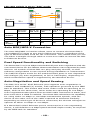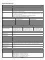
1
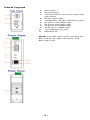
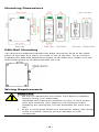
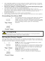
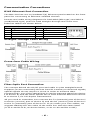
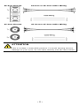
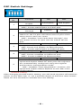
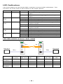
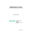
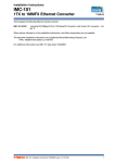
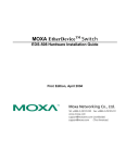
IMC-21A Hardware Installation Guide Moxa Industrial Media Converter Third Edition, June 2012 2012 Moxa Inc. All rights reserved. Reproduction without permission is prohibited. P/N: 1802000210021 Overview The Moxa Industrial Media Converter IMC-21A series consists of entry-level 10/100BaseT(X) to 100BaseFX media converters that provide a cost-effective solution, and are specially designed for reliable and stable operation in harsh industrial environments. NOTE Throughout this Hardware Installation Guide, we use IMC as an abbreviation for Industrial Media Converter: IMC = Industrial Media Converter Package Checklist Moxa’s IMC-21A is shipped with the following items. If any of these items is missing or damaged, please contact your customer service representative for assistance. • • • IMC-21A media converter Hardware installation guide (this guide) Warranty card Features • • • • • • • Power inputs: 12 to 48 VDC The TP port’s connection speed, Half/Full duplex mode, and Force/Auto mode are all DIP switch selectable The fiber port’s Half/Full duplex mode is DIP switch selectable Supports Link Fault Pass-Through (LFP) DIN-Rail mountable Multi mode and single mode models with SC or ST fiber connectors are available Operating temperature range from -40 to 75°C (T models) -2- Panel Layout 1. 2. 3. 4. 5. 6. 7. 8. 9. 10. 11. DIP switch Reset button Terminal block for power input and grounding Power input LED 100BaseFX (SC/ST connector) port FX port's 100 Mbps LED FX port's FDX/COL LED TP port’s 100 Mbps LED TP port's 10 Mbps LED 10/100BaseT(X) port DIN-Rail kit NOTE: The IMC-21A series includes the IMC-21A-M-SC, IMC-21A-M-ST, and IMC-21A-S-SC. -3- Mounting Dimensions DIN-Rail Mounting The aluminum DIN-Rail attachment plate should be fixed to the back panel of the IMC-21A when you take it out of the box. If you need to reattach the DIN-Rail attachment plate to the IMC-21A, make sure the stiff metal spring is situated towards the top. Wiring Requirements Safety First! • • • Be sure to disconnect the power cord before installing and/or wiring your Moxa IMC. Calculate the maximum possible current in each power wire and common wire. Observe all electrical codes dictating the maximum current allowable for each wire size. If the current goes above the maximum rating, the wiring could overheat, causing serious damage to your equipment. -4- • • • • • Use separate paths to route wiring for power and devices. If power wiring and device wiring paths must cross, make sure the wires are perpendicular at the intersection point. Do not run signal or communications wiring and power wiring in the same wire conduit. To avoid interference, wires with different signal characteristics should be routed separately. You can use the type of signal transmitted through a wire to determine which wires should be kept separate. The rule of thumb is that wiring that shares similar electrical characteristics can be bundled together. Keep input wiring and output wiring separated. We strongly advise that you label wiring to all devices in the system. Grounding the Moxa IMC Grounding and wire routing help limit the effects of noise due to electromagnetic interference (EMI). Run the ground connection from the right most connector of the 3-contact terminal block to the grounding surface prior to connecting devices. ATTENTION This product is intended to be mounted to a well-grounded mounting surface such as a metal panel. Wiring the Power Inputs The two left-most contacts of the 3-contact terminal block connector on the IMC’s top panel are used for the IMC’s DC inputs. Take the following steps to wire the IMC’s DC power inputs: STEP 1: Insert the negative/positive DC wires into the V-/V+ terminals. STEP 2: To keep the DC wires from pulling loose, use a small flat-blade screwdriver to tighten the wire-clamp screws on the front of the terminal block connector. STEP 3: Insert the plastic terminal block connector prongs into the terminal block receptor, which is located on IMC’s top panel. -5- Communication Connections RJ45 Ethernet Port Connection The IMC-21A has one 10/100BaseT(X) Ethernet port located on the front panel for connecting to Ethernet-enabled devices. Pinouts and cable wiring diagrams for both MDI (NIC-type) and MDI-X (HUB/switch-type) ports for both straight-through and cross-over Ethernet cables are shown below: MDI Pin 1 2 3 6 Port Pinouts Signal Tx+ TxRx+ Rx- MDI-X Port Pinouts Pin Signal 1 Rx+ 2 Rx3 Tx+ 6 Tx- 8-pin RJ45 Straight-Through Cable Wiring Cross-Over Cable Wiring Fiber Optic Port Connection The concept behind the SC/ST port and cable is quite straightforward. Suppose you are connecting devices I and II. Contrary to electrical signals, optical signals do not require a circuit in order to transmit data. Consequently, one of the optical lines is used to transmit data from device I to device II, and the other optical line is used transmit data from device II to device I, for full-duplex transmission. All you need to remember is to connect the Tx (transmit) port of device I to the Rx (receive) port of device II, and the Rx (receive) port of device I to the Tx (transmit) port of device II. If you make your own cables, we suggest labeling the two sides of the same line with the same letter (A-to-A and B-to-B, as shown below, or A1-to-A2 and B1-to-B2). -6- SC-Port Pinouts SC-Port to SC-Port Cable Wiring ST-Port Pinouts ST-Port to ST-Port Cable Wiring ATTENTION This is a Class 1 Laser/LED product. To avoid causing serious damage to your eyes, do not stare directly into the laser beam. -7- DIP Switch Settings DIP No. 1 2 3 4 Function ON OFF Force Fiber Port Full Duplex* Half Duplex Duplex “ON”: Forces Full Duplex on Fiber port. “OFF”: Forces Half Duplex on Fiber port. Link Fault Pass Enable* Disable Through “ON”: Enables “Link Fault Pass Through”, the link status on the TX port will inform the FX port of the same device and vice versa. “OFF”: Disables “Link Fault Pass Through”, the link status on the TX port will not inform the FX port. Force TP Duplex Full Duplex* Half Duplex (Only when Auto Negotiation (DIP 5) is disabled) “ON”: Forces Full Duplex on Ethernet port. “OFF”: Forces Half Duplex on Ethernet port. Force TP Speed 100Mbps* 10Mbps (Only when Auto Negotiation (DIP 5) is disabled) “ON”: Forces 100Mbps on Ethernet port. “OFF”: Forces 10Mbps on Ethernet port. Auto Negotiation Enable* Disable “ ON”: Enables “Auto Negotiation” function, the speed and duplex states for each port link segment are automatically configured using the highest 5 performance interoperation mode. “ OFF”: Disables “Auto Negotiation” function, the speed and duplex states depend on the DIP 3 & 4 configuration. *Default setting After changing the DIP switch setting, you will need to power off and then power on the IMC-21A, or use a pointed object to hold the reset button down for five seconds to activate the new setting. -8- LED Indicators The front panel of the Moxa IMC contains several LED indicators. The function of each LED is described in the table below. LED PWR Color AMBER State On Off 100M (FX) GREEN FDX/COL GREEN (FX) On Blinking Off On Blinking Off 100M (TP) GREEN 10M (TP) GREEN On Blinking Off On Blinking Off Description Power is being supplied to the power input. Power is not being supplied to the power input. FX port’s 100 Mbps link is active. Data is being transmitted at 100 Mbps. FX Port’s 100 Mbps link is inactive. 100BaseFX port is transmitting in full duplex mode. A data collision has occurred. 100BaseFX port is transmitting in half duplex mode. TP port’s 100 Mbps link is active. Data is being transmitted at 100 Mbps. TP port’s 100 Mbps link is inactive. TP port’s 10 Mbps link is active. Data is being transmitted at 10 Mbps. TP port’s 10 Mbps link is inactive. LFP: DIP switch is set to “LFP” mode DUTB DUTA F1 Device1 F2 TP1 Device1 TP LED OFF TP1 Faulted F1 Faulted OFF F2 Faulted OFF TP2 OFF Faulted TP2 Device2 DUTA TP DUTA FO DUTB FO DUTB TP Device 2 LNK LED LED LED LNK LED TP LED OFF OFF OFF OFF OFF OFF OFF OFF OFF OFF OFF -9- OFF OFF OFF OFF OFF OFF OFF OFF OFF LFP: DIP switch is set to “DIS” mode DUTB DUTA F1 Device1 F2 TP1 Device1 TP LED OFF TP1 Faulted F1 Faulted ON F2 Faulted ON TP2 ON Faulted TP2 Device2 DUTA TP DUTA FO DUTB FO DUTB TP Device 2 LNK LED LED LED LNK LED TP LED OFF ON ON ON ON ON ON ON OFF OFF ON OFF OFF ON ON ON OFF ON ON OFF Auto MDI/MDI-X Connection The Auto MDI/MDI-X function allows users to connect the Moxa IMC’s 10/100BaseT(X) ports to any kind of Ethernet device, regardless of the type of Ethernet cable used for the connection. This means that you can use either a straight-through cable or cross-over cable to connect the IMC to Ethernet devices. Dual Speed Functionality and Switching The Moxa IMC’s 10/100 Mbps switched RJ45 port auto negotiates with the connected device for the fastest data transmission rate supported by both devices. All models of Moxa IMC are plug-and-play devices, so that software configuration is not required during installation or maintenance. The half/full duplex mode for the switched RJ45 ports is user dependent and changes (by auto-negotiation) to full or half duplex, depending on which transmission speed is supported by the attached device. Auto-Negotiation and Speed Sensing The IMC-21A series’ RJ45 Ethernet port supports auto-negotiation in 10BaseT and 100BaseT(X) modes, with operation governed by the IEEE 802.3u standard. This means that some nodes could be operating at 10 Mbps, while at the same time, other nodes are operating at 100 Mbps. Auto-negotiation takes place when an RJ45 cable connection is made, and then each time a LINK is enabled. The Moxa IMC advertises its capability for using either 10 Mbps or 100 Mbps transmission speeds, with the device at the other end of the cable expected to advertise similarly. Depending on which type of device is connected, the devices will agree to operate at either 10 Mbps or 100 Mbps. If a Moxa IMC’s RJ45 Ethernet port is connected to a non-negotiating device, it will default to 10 Mbps speed and half-duplex mode, as required by the IEEE 802.3u standard. - 10 - Specifications Technology Standards Interface RJ45 Port Fiber Port LED Indicators DIP Switch IEEE802.3, 802.3u, 802.3x 10/100BaseT(X) 100BaseFX (SC, ST connectors available) Power, 10/100M (TP port), 100M (Fiber port), FDX/COL (Fiber port) The following are DIP switch selectable: TP port’s connection speed, Half/Full duplex mode, and Force/Auto mode Fiber connection’s Half/Full duplex mode Link Fault Pass-Through (LFP) Fiber Optics Multi mode (100BaseFX) 5 1300 -20 -14 -34 to -30 Single mode (100BaseFX) 40 1310 -5 0 -36 to -32 Distance, km Wavelength, nm Min. Tx Output, dBm Max. Tx Output, dBm Sensitivity, dBm Power Requirements Input Voltage 12 to 48 VDC Power M-SC: M-ST: S-SC: Consumption 245 mA @ 12 V 265 mA @ 12 V 255 mA @ 12 V 130 mA @ 24 V 135 mA @ 24 V 130 mA @ 24 V 70 mA @ 48 V 75 mA @ 48 V 70 mA @ 48 V Connection Removable 3-contact terminal block Overload Current 1.1 A Protection Reverse Polarity Present Protection Physical Characteristics Casing IP30 protected, metal case Dimensions 30 × 115 × 70 mm (1.19 x 4.53 x 2.76 in) Weight 170 g Installation DIN-Rail mounting Environmental Limits Operating Standard models: -10 to 60°C (14 to 140°F) Temperature Wide temp. models: -40 to 75°C (-40 to 167°F) Storage -40 to 75°C (-40 to 167°F) Temperature Ambient Relative 5 to 95% (non-condensing) Humidity Regulatory Approvals Safety UL 60950-1 EMI FCC Part 15, CISPR (EN55022) class A EMS EN 61000-4-2 (ESD) Level 3 EN 61000-4-3 (RS) Level 2 EN 61000-4-4 (EFT) Level 2 EN 61000-4-5 (Surge) Level 2 EN 61000-4-6 (CS) Level 2 - 11 - Shock Free Fall Vibration Warranty IEC 60068-2-27 IEC 60068-2-32 IEC 60068-2-6 5 years Federal Communications Commission Statement FCC—This device complies with part 15 of the FCC Rules. Operation is subject to the following two conditions: (1) This device may not cause harmful interference, and (2) this device must accept any interference received, including interference that may cause undesired operation. FCC WARNING This equipment has been tested and found to comply with the limits for a Class A digital device, pursuant to part 15 of the FCC Rules. These limits are designed to provide reasonable protection against harmful interference when the equipment is operated in a commercial environment. This equipment generates, uses, and can radiate radio frequency energy, and if not installed and used in accordance with the instruction manual, may cause harmful interference to radio communications. Operation of this equipment in a residential area is likely to cause harmful interference, in which case the user will be required to correct the interference at his or her own expense. Technical Support Contact Information www.moxa.com/support Moxa Americas: Toll-free: 1-888-669-2872 Tel: 1-714-528-6777 Fax: 1-714-528-6778 Moxa China (Shanghai office): Toll-free: 800-820-5036 Tel: +86-21-5258-9955 Fax: +86-21-5258-5505 Moxa Europe: Tel: +49-89-3 70 03 99-0 Fax: +49-89-3 70 03 99-99 Moxa Asia-Pacific: Tel: +886-2-8919-1230 Fax: +886-2-8919-1231 - 12 -