Transcript
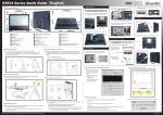
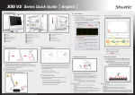
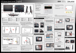
. X50V3L Series Quick Guide【English】 E Front/Rear/Side View E 4 Point Calibration (Optional) Touch and hold the center of the target. Run the screen calibration 01 02 09 10 03 17 18 04 program and correct 4 point locations on screen with the panel. Click Start / All Programs / eGalax Touch / Configure Utility Select [Tools] tab and click [4 Points Calibration] 19 11 12 13 05 14 06 20 21 Repeat on four corners and the screen will adjust automatically. 23 22 15 07 08 08 16 Hold Touch 02 Stand / Handle Microphone 03 Webcam 11 04 LCD Display (Single Touch / Non Touch)(Optional) 12 Microphone Jack 20 VGA Port Power Input 05 WiFi LED 13 21 Printer Port (Optional) 06 Hard disk drive LED 14 Headphone / Line-out Jack LAN Port 22 COM Ports (Optional) 07 Power LED 15 23 Kensington® Lock Port 08 Stereo speakers 16 USB 2.0 Ports Stand / Handle 01 09 10 Power Button 17 HDMI Port Stylus pen SD card reader 18 USB 2.0 Ports 19 E Placing on the desk Place the X50V3L on a flat surface such as a table (Picture 1), and pull the stand upwards to an angle of 30° (Picture 2). To carry or move your X50V3L fully extend the angle to 180° (Picture 3). 1. When the 4 points calibration completed, press [OK] to continue. DCIN E How to use the Touch Panel (Optional) To place the machine on the desk and to carry it, do the following: 2. 3. X50V3L brings digital life for an easy touch experience.Experience the ease of OK managing your digital life with a few touches or the use of the stylus pen. The touch of your finger replaces the mouse and is all you need to interact with the X50V3L . ・Touch = left-click on the mouse ・Touch and hold = right-click on the mouse E Safety Information Read the following precautions before setting up a Shuttle X50V3L . CAUTION Do not walk on the power cord or allow anything to rest on it. The warranty does not apply to the products that have been disassembled by users. CAUTION Danger of explosion if battery is incorrectly replaced. Replace only with the same or equivalent type recommended by the manufacturer. Dispose of used batteries according to the manufacturer’s instructions. A. Begin Installation 2. Unscrew three screws of the bracket and remove it. 3. Mount HDD into the bracket with four screws. 4. Carefully push down the memory module until it snaps into the locking mechanism. 5. Repeat the above steps to install additional memory modules, if required. For safety reasons, please ensure that the power cord is disconnected before opening the case. 1. Remove the cover on the back of X50V3L first, unscrew four screws of the stand mount and remove the stand. Cover Latch Latch Screw 180 DIMM2 4. As shown, install the HDD & bracket in the chassis and push it towards the direction as indicated by the red arrow to connect the HDD connector. 30 6. Replace the VESA Base and refasten four screws. Screw 5. Tighten the HDD & bracket with three screws. E VESA Base Powering on the system Stand / Handle Follow the steps (1~3) below to connect the AC adapter to the DCIN jack. DIMM1 Press the Power Button to turn on the system. E VESA mounting it to the wall 2. Unscrew four screws of the back cover and remove it. HDD Connector D. Complete 1. Replace the back cover, stand and refasten eight screws. C. Memory Module Installation If you install only one memory module in your system, install it in the slot labeled "DIMM2". 1. Locate the SODIMM slot on the mainboard. B. HDD Installation 1. Unscrew four screws of the VESA Base and remove it first. 2. Align the notch of the memory module with the one of the memory slot. SODIMM slot Back Cover Screw Stand / Handle 2. Replace the cover, complete. E Cleaning the screen Follow these guidelines for cleaning the outside and handling the screen of the computer: Turn off the system and disconnect all cables. Use a damp, or cleaning cloth, soft, lint-free cloth with gentle water only and gently wipe the screen surface. Do not spray liquid directly on the screen. Note: The product’s color and specification will depend upon the actually shipping product. If you are mounting your X50V3L to the wall, remove the cover on the back of X50V3L first. Unscrew 4 screws of the stand mount and remove the stand. The VESA standard lets users mount it on to walls easily. Please refer to the user guide of the wall/arm mount kit you bought to install it. Note :X50V3L can be mounted to a wall using a VESA compatible 100 x 100mm wall/arm bracket. Screw VESA Base 3. Gently insert the module into the slot in a 45-degree angle. 1 2 45-degree angle 53R-X50V33-2501