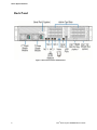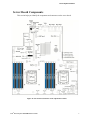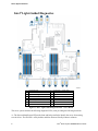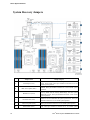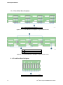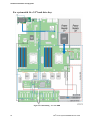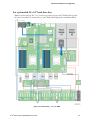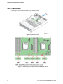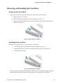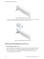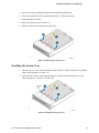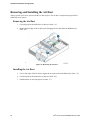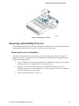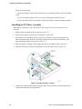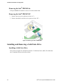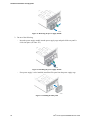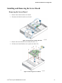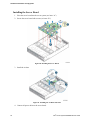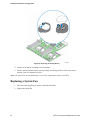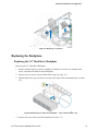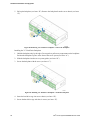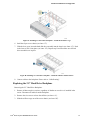
1
Intel® Server System R2000BB Family Service Guide A Guide for Technically Qualified Assemblers of Intel® identified Subassemblies/Products Order Number: G65887-003 Disclaimer Disclaimer ® Information in this document is provided in connection with Intel products. No license, express or implied, by estoppel or otherwise, to any intellectual property rights is granted by this document. Except as provided in Intel’s Terms and Conditions of Sale for such products, Intel assumes no liability whatsoever, and Intel disclaims any express or implied warranty, relating to sale and/or use of Intel products including liability or warranties relating to fitness for a particular purpose, merchantability, or infringement of any patent, copyright or other intellectual property right. Intel products are not designed, intended or authorized for use in any medical, life saving, or life sustaining applications or for any other application in which the failure of the Intel product could create a situation where personal injury or death may occur. Intel may make changes to specifications and product descriptions at any time, without notice. Intel server boards contain a number of high-density VLSI and power delivery components that need adequate airflow for cooling. Intel’s own chassis are designed and tested to meet the intended thermal requirements of these components when the fully integrated system is used together. It is the responsibility of the system integrator that chooses not to use Intel developed server building blocks to consult vendor datasheets and operating parameters to determine the amount of airflow required for their specific application and environmental conditions. Intel Corporation can not be held responsible if components fail or the server board does not operate correctly when used outside any of their published operating or non-operating limits. Intel, Intel Pentium, and Intel Xeon are trademarks or registered trademarks of Intel Corporation or its subsidiaries in the United States and other countries. * Other names and brands may be claimed as the property of others. Copyright © 2012 Intel Corporation. All Rights Reserved. ii ® Intel Server System R2000BB Service Guide Safety Information Safety Information Important Safety Instructions Read all caution and safety statements in this document before performing any of the instructions. See also Intel Server Boards and Server Chassis Safety Information on the Intel® Server Deployment Toolkit 3.0 CD and/or at http://www.intel.com/support/motherboards/server/sb/cs-010770.htm. Wichtige Sicherheitshinweise Lesen Sie zunächst sämtliche Warnund Sicherheitshinweise in diesem Dokument, bevor Sie eine der Anweisungen ausführen. Beachten Sie hierzu auch die Sicherheitshinweise zu IntelServerplatinen und Servergehäusen auf der Intel® Server Deployment Toolkit 3.0 CD oder unter http://www.intel.com/support/motherboards/server/sb/cs-010770.htm. Consignes de sécurité Lisez attention toutes les consignes de sécurité et les mises en garde indiquées dans ce document avant de suivre toute instruction. Consultez Intel Server Boards and Server Chassis Safety Information sur le Intel® Server Deployment Toolkit 3.0 CD ou bien rendez-vous sur le site http://www.intel.com/support/motherboards/server/sb/cs-010770.htm. Instrucciones de seguridad importantes Lea todas las declaraciones de seguridad y precaución de este documento antes de realizar cualquiera de las instrucciones. Vea Intel Server Boards and Server Chassis Safety Information en el Intel® Server Deployment Toolkit 3.0 CD y/o en http://www.intel.com/support/motherboards/server/sb/cs-010770.htm. 重要安全指导 在执行任何指令之前,请阅读本文档中的所有注意事项及安全声明。和/或 http://www.intel.com/support/motherboards/server/sb/cs-010770.htm 上的 Intel® Server Boards and Server Chassis Safety Information(《Intel 服务器主板与服务器机箱安全信息》)。 ® Intel Server System R2000BB Service Guide iii Warnings Warnings Heed safety instructions: Before working with your server product, whether you are using this guide or any other resource as a reference, pay close attention to the safety instructions. You must adhere to the assembly instructions in this guide to ensure and maintain compliance with existing product certifications and approvals. Use only the described, regulated components specified in this guide. Use of other products/components will void the UL listing and other regulatory approvals of the product and will most likely result in noncompliance with product regulations in the region(s) in which the product is sold. System power on/off: The power button DOES NOT turn off the system AC power. To remove power from the system, you must unplug the AC power cord from the wall outlet. Make sure the AC power cord is unplugged before you open the chassis, add, or remove any components. Hazardous conditions, devices and cables: Hazardous electrical conditions may be present on power, telephone, and communication cables. Turn off the server and disconnect the power cord, telecommunications systems, networks, and modems attached to the server before opening it. Otherwise, personal injury or equipment damage can result. Electrostatic discharge (ESD) and ESD protection: ESD can damage disk drives, boards, and other parts. We recommend that you perform all procedures in this chapter only at an ESD workstation. If one is not available, provide some ESD protection by wearing an antistatic wrist strap attached to chassis ground - any unpainted metal surface - on your server when handling parts. ESD and handling boards: Always handle boards carefully. They can be extremely sensitive to ESD. Hold boards only by their edges. After removing a board from its protective wrapper or from the server, place the board component side up on a grounded, static free surface. Use a conductive foam pad if available but not the board wrapper. Do not slide board over any surface. Installing or removing jumpers: A jumper is a small plastic encased conductor that slips over two jumper pins. Some jumpers have a small tab on top that you can grip with your fingertips or with a pair of fine needle nosed pliers. If your jumpers do not have such a tab, take care when using needle nosed pliers to remove or install a jumper; grip the narrow sides of the jumper with the pliers, never the wide sides. Gripping the wide sides can damage the contacts inside the jumper, causing intermittent problems with the function controlled by that jumper. Take care to grip with, but not squeeze, the pliers or other tool you use to remove a jumper, or you may bend or break the pins on the board. iv ® Intel Server System R2000BB Service Guide Preface Preface About this Manual This manual is written for system technicians who are responsible for troubleshooting, upgrading, and repairing this server system. This document provides a brief overview of the features of the server board/chassis, a list of accessories or other components you may need, troubleshooting information, and instructions on how to add and replace components on the Intel® Server System R2000BB family products. For the latest revision of this manual, go to http://www.intel.com/support. Manual Organization Chapter 1 provides a brief overview of the Intel® Server System R2000BB family. In this chapter, you will find a list of the server system features, and figures of the system and components to help you identify your system components and their locations. Chapter 2 provides instructions on adding and replacing components. Use this chapter for step-bystep instructions and diagrams for installing or replacing components such as the fan, power supply, and front panel board, among other components. Chapter 3 provides instructions on using the utilities that are shipped with the board or that may be required to update the system. This includes information for navigating through the BIOS Setup screens, performing a BIOS update, and resetting the password or BIOS defaults. The back of this manual provides technical specifications, regulatory information, LED Decoder, "getting help" information, and Intel® Server Issue Report Form. Additional Information and Software For additional information about this family of products or any of their supported accessories, refer to the following resources available at http://www.intel.com/support. Table 1. Server System References For this information or software For in-depth technical information about this product. Use this Document or Software ® Intel Server System R2000BB Product Family Technical Product Specification Intel® Server Specification Board S2400BB Technical Product For a quick guide of how to assemble the server system and install components Intel® Server System R2000BB Product Family Quick Integration Guide For product list and supported Intel spares and accessories Spares and Accessories List and Configuration Guide For server configuration guidance and compatibility Intel® Server Configurator tool http://serverconfigurator.intel.com For system power budget guidance Power Budget Tool For system firmware updates and onboard device drivers and software to manage your Intel® Server System. Intel® Server Deployment & Management DVD Product Safety and Regulatory document Intel Server Products - Product Safety and Regulatory Compliance Document ® Intel Server System R2000BB Service Guide v Table of Contents Table of Contents Safety Information .................................................................................................iii Preface ....................................................................................................................v 1 Server System Features ......................................................................................1 Server System Feature Overview ...............................................................................................1 Server System Components ......................................................................................................3 Hot Swap Hard Drive Bay and Front Panel Options .....................................................................4 Front Panel .............................................................................................................................5 Back Panel ..............................................................................................................................6 Server Board Components ........................................................................................................7 Intel® Light-Guided Diagnostics ................................................................................................8 System Recovery Jumpers ......................................................................................................10 Peripheral Devices .................................................................................................................11 2 Hardware Installations and Upgrades ..............................................................17 Before You Begin ..................................................................................................................17 Tools and Supplies Needed ............................................................................................17 System Reference .........................................................................................................17 Cable Routing .......................................................................................................................18 For system with 8 x 3.5” hard drive bay: ..........................................................................19 For system with 12 x 3.5” hard drive bay: ........................................................................20 For system with 8 x 2.5” hard drive bay: ..........................................................................21 For system with 16 x 2.5” hard drive bay: ........................................................................22 For system with 24 x 2.5” hard drive bay: ........................................................................23 Fan Connections ....................................................................................................................24 Removing and Installing the Front Bezel ..................................................................................25 Removing the Front Bezel ..............................................................................................25 Installing the Front Bezel ...............................................................................................25 Removing and Installing the System Cover ...............................................................................26 Removing the System Cover ..........................................................................................26 Installing the System Cover ............................................................................................27 Removing and Installing the Air Duct ......................................................................................28 Removing the Air Duct ..................................................................................................28 Installing the Air Duct ...................................................................................................28 Removing and Installing Processor ..........................................................................................29 Removing Processor Heatsink(s).....................................................................................29 Installing the Processor ..................................................................................................30 Installing Processor Heatsink(s) ......................................................................................32 Removing the Processor.................................................................................................33 Installing and Removing Memory ............................................................................................33 Installing Memory .........................................................................................................33 Removing Memory .......................................................................................................34 Installing a Hot-swap Hard Disk Drive .....................................................................................34 Installing a Hard Disk Drive into 3.5” Hard Drive Carrier .................................................. 34 Installing a Hard Disk Drive into 2.5” Hard Drive Carrier .................................................. 36 Removing and Installing the PCI Riser Assembly ......................................................................37 vi ® Intel Server System R2000BB Service Guide Table of Contents Removing the PCI Riser Assembly .................................................................................37 Installing the PCI Riser Assembly ...................................................................................38 Installing and Removing a PCI Add-in Card .............................................................................39 Installing a PCI Add-in Card ..........................................................................................39 Removing a PCI Add-in Card .........................................................................................39 Replacing a PCI Riser Card.....................................................................................................40 Removing a PCI Riser Card ...........................................................................................40 Installing a PCI Riser Card .............................................................................................41 Installing and Removing a Slimline Optical Drive .....................................................................41 Installing a Slimline Optical Drive ..................................................................................42 Removing a Slimline Optical Drive .................................................................................42 Installing and Removing Intel® I/O Expansion Module ...............................................................43 Installing Intel® I/O Expansion Module ............................................................................43 Removing Intel® I/O Expansion Module ...........................................................................43 Installing and Removing the Intel® RAID C600 Upgrade Key .....................................................44 Installing the Intel® RAID C600 Upgrade Key ..................................................................44 Removing the Intel® RAID C600 Upgrade Key ................................................................44 Installing and Removing the Intel® Remote Management Module 4 ............................................. 45 Installing the Intel® RMM4 Lite......................................................................................45 Install the Intel® RMM4 NIC ..........................................................................................45 Removing the Intel® RMM4 Lite ....................................................................................46 Removing the Intel® RMM4 NIC ....................................................................................46 Installing and Removing a Solid State Drive .............................................................................46 Installing a Solid State Drive ..........................................................................................46 Removing a Solid State Drive .........................................................................................47 Installing and Removing the Intel® RAID Smart Battery ............................................................48 Installing the Intel® RAID Smart Battery .........................................................................48 Removing the Intel® RAID Smart Battery ........................................................................48 Replacing the Power Supply ...................................................................................................49 Installing and Removing the Server Board ................................................................................51 Removing the Server Board............................................................................................51 Installing the Server Board .............................................................................................52 Replacing the Backup Battery .................................................................................................53 Replacing a System Fan .........................................................................................................54 Replacing the Backplane ........................................................................................................55 Replacing the 3.5” Hard Drive Backplane ........................................................................55 Replacing the 2.5” Hard Drive Backplane ........................................................................57 Replacing the Intel® RAID Expander RS2CV360/RS2CV240 ......................................................60 Removing the Intel® RAID Expander ...............................................................................60 Installing the Intel® RAID Expander ................................................................................61 Installing and Removing the Rack Handles ...............................................................................61 Installing the Rack Handles ............................................................................................61 Removing the Rack Handles...........................................................................................62 Installing and Removing the Storage Front Panel .......................................................................62 Installing the Storage Front Panel....................................................................................62 Removing the Storage Front Panel ..................................................................................63 3 Server Utilities .................................................................................................65 Using the BIOS Setup Utility ..................................................................................................65 Entering BIOS Setup .....................................................................................................65 ® Intel Server System R2000BB Service Guide vii Table of Contents If You Cannot Access Setup ...........................................................................................65 Setup Menus.................................................................................................................65 Upgrading the BIOS ......................................................................................................67 Clearing the Password ...................................................................................................67 Restoring the BIOS Defaults ..........................................................................................67 Appendix A: Technical Reference .........................................................................68 Power Supply Input Voltages .........................................................................................68 Power Supply Output Voltages .......................................................................................68 System Environmental Specifications ..............................................................................68 Appendix B: Regulatory and Compliance Information ..........................................70 Appendix C: Getting Help .....................................................................................71 Warranty Information ....................................................................................................71 Appendix D: Intel® Server Issue Report Form .......................................................72 viii ® Intel Server System R2000BB Service Guide List of Figures List of Figures Figure 1. Intel® Server System R2000BB ....................................................................................1 Figure 2. Intel® Server System R2000BB Components ...............................................................4 Figure 4. 3.5" Hard Drive Bay - 12 Drive Configuration ...............................................................4 Figure 5. 2.5" Hard Drive Bay - 8 Drive Configuration .................................................................5 Figure 6. 2.5" Hard Drive Bay - 16 Drive Configuration ...............................................................5 Figure 7. 2.5" Hard Drive Bay - 24 Drive Configuration ...............................................................5 Figure 8. Front Panel Options .....................................................................................................5 Figure 9. Back Panel Feature Identification .................................................................................6 Figure 10. Server Board Connector and Component Locations ..................................................7 Figure 11. Intel® Light-Guided Diagnostic LEDs - Server Board ..................................................8 Figure 12. Configuration Jumpers .............................................................................................11 Figure 13. Optional Peripherals (16x2.5-inch hard drive bays as shown) .................................. 11 Figure 14. Front view of Front Bezel .........................................................................................13 Figure 15. 8 x 3.5-inch Hard Drive Backplane Components (Front View) .................................. 13 Figure 16. 8 x 3.5-inch Hard Drive Backplane Components (Rear View)................................... 13 Figure 17. 12 x 3.5-inch Hard Drive Backplane Components (Front View) ................................ 14 Figure 18. 12 x 3.5-inch Hard Drive Backplane Components (Rear View)................................. 14 Figure 19. 8 x 2.5-inch Hard Drive Backplane Components (Front View) .................................. 15 Figure 20. 8 x 2.5-inch Hard Drive Backplane Components (Rear View)................................... 15 Figure 21. Internal Intel® RAID Expander Cards Components (Top View) ................................. 15 Figure 22. Cable Routing – 8 x 3.5” HDD ..................................................................................19 Figure 23. Cable Routing – 12 x 3.5” HDD ................................................................................20 Figure 24. Cable Routing – 8 x 2.5” HDD ..................................................................................21 Figure 25. Cable Routing – 16 x 2.5” HDD ................................................................................22 Figure 26. Cable Routing – 24 x 2.5” HDD ................................................................................23 Figure 27. System Fan Order ....................................................................................................24 Figure 28. Connecting the Fan Power Cables to the Mother Board ........................................... 24 Figure 29. Removing the Front Bezel ........................................................................................25 Figure 30. Installing the Front Bezel ..........................................................................................25 Figure 31. Installing the badge to the front bezel .......................................................................26 Figure 32. Removing the badge from the front bezel .................................................................26 Figure 33. Removing the System Cover ....................................................................................27 Figure 34. Installing the System Cover ......................................................................................27 Figure 35. Removing the Air Duct .............................................................................................28 Figure 36. Installing the Air Duct ...............................................................................................29 Figure 37. Removing Processor Heatsink .................................................................................30 Figure 38. Installing Processor – Open the Socket Lever ..........................................................30 Figure 39. Installing Processor – Open the Load Plate..............................................................31 Figure 40. Installing Processor – Install the Processor ..............................................................31 Figure 41. Installing Processor – Remove the Cover.................................................................32 Figure 42. Installing Processor – Close the Load Plate .............................................................32 Figure 43. Installing Processor – Latch the Locking Lever ........................................................32 Figure 44. Installing Processor Heatsink ...................................................................................33 Figure 45. Installing Memory .....................................................................................................34 Figure 46. Installing Hard Disk Drive – Removing 3.5” HDD carrier........................................... 34 Figure 47. Installing Hard Disk Drive – Removing 3.5” HDD interface bracket........................... 35 Figure 48. Installing Hard Disk Drive – Installing 3.5” HDD........................................................35 ® Intel Server System R2000BB Service Guide ix List of Figures Figure 49. Installing Hard Disk Drive – Installing 2.5” HDD........................................................35 Figure 50. Installing Hard Disk Drive – Inserting 3.5” HDD assembly ........................................ 36 Figure 51. Installing Hard Disk Drive – Removing 2.5” HDD carrier........................................... 36 Figure 52. Installing Hard Disk Drive – Removing plastic drive blank ........................................ 36 Figure 53. Installing Hard Disk Drive – Installing 2.5” HDD........................................................37 Figure 54. Installing Hard Disk Drive – Inserting 2.5” HDD assembly ........................................ 37 Figure 55. Removing PCI Riser Assembly ................................................................................37 Figure 56. Installing PCI Riser Assembly ..................................................................................38 Figure 57. Installing a PCI Add-In Card .....................................................................................39 Figure 58. Removing a PCI Add-In Card ...................................................................................40 Figure 59. Removing the PCI Riser Card ..................................................................................41 Figure 60. Installing the PCI Riser Card ....................................................................................41 Figure 61. Installing the Plastic Guide to the Optical Drive ........................................................42 Figure 62. Installing an Optical Drive .........................................................................................42 Figure 63. Removing the Slimline Optical Drive ........................................................................42 Figure 64. Installing Intel® I/O Expansion Module ......................................................................43 Figure 65. Removing an I/O Expansion Module ........................................................................44 Figure 66. Installing the Intel® RAID C600 Upgrade Key ...........................................................44 Figure 67. Installing the Intel® RMM4 Lite .................................................................................45 Figure 68. Installing the Intel® RMM4 NIC .................................................................................45 Figure 69. Removing the Intel® RMM4 NIC ...............................................................................46 Figure 70. Installing a SSD........................................................................................................47 Figure 71. Removing a SSD......................................................................................................47 Figure 72. Installing the Intel® RAID Smart Battery....................................................................48 Figure 73. Removing the Intel® RAID Smart Battery..................................................................49 Figure 74. Removing the filler panel ..........................................................................................49 Figure 75. Removing the power supply module......................................................................... 50 Figure 76. Installing the power supply module...........................................................................50 Figure 77. Installing the filler panel ............................................................................................50 Figure 78. Removing the Air Duct Side Wall .............................................................................51 Figure 79. Removing the Server Board .....................................................................................51 Figure 80. Installing the Server Board .......................................................................................52 Figure 81. Installing the Air Duct Side Wall ...............................................................................52 Figure 82. Replacing the Backup Battery ..................................................................................54 Figure 83. Replacing a system fan ............................................................................................55 Figure 84. Removing 3.5” hard drive backplane – remove the hard drive cage ......................... 55 Figure 85. Removing 3.5” hard drive backplane - remove the backplane .................................. 56 Figure 86. Installing 3.5” hard drive backplane – install the backplane ...................................... 56 Figure 87. Installing 3.5” hard drive backplane – install the hard drive cage .............................. 57 Figure 88. Installing 3.5” hard drive backplane – install the stiffener and hard drives ................ 57 Figure 89. Removing 2.5” hard drive backplane – remove the stiffener ..................................... 58 Figure 90. Removing 2.5” hard drive backplane – remove the hard drive cage ......................... 58 Figure 91. Removing 2.5” hard drive backplane – remove the backplane ................................. 59 Figure 92. Installing 2.5” hard drive backplane – install backplane ............................................ 59 Figure 93. Installing 2.5” hard drive backplane – install hard drive cage .................................... 59 Figure 94. Installing 2.5” hard drive backplane – install the stiffener.......................................... 60 Figure 95. Removing the Intel® RAID Expander .........................................................................60 Figure 96. Intalling the Intel® RAID Expander.............................................................................61 Figure 97. Installing the Rack Handle ........................................................................................61 Figure 98. Removing the Rack Handle ......................................................................................62 x ® Intel Server System R2000BB Service Guide List of Figures Figure 99. Installing the interposer card ....................................................................................62 Figure 100. Installing the storage front panel ............................................................................63 Figure 101. Installing the storage front panel ............................................................................63 Figure 102. Installing the interposer card ..................................................................................64 ® Intel Server System R2000BB Service Guide xi List of Tables List of Tables Table 1. Server System References............................................................................................ v Table 2. Intel® Server System R2000BB Feature Summary ........................................................1 Table 3. Hard Disk Drive Options ..............................................................................................12 Table 4. BIOS Setup: Keyboard Command Bar ........................................................................66 Table 5. Power Supply Output Capability ..................................................................................68 Table 6. System Environmental Limits Summary ......................................................................68 xii ® Intel Server System R2000BB Service Guide Server System Features 1 Server System Features This chapter briefly describes the main features of the Intel® Server System R2000BB family. This includes illustrations of the products, a list of the server system features, and diagrams showing the location of important components and connections on the server systems. Figure 1. Intel® Server System R2000BB Server System Feature Overview Table 3 sumarizes the features of the the server systems. Table 2. Intel® Server System R2000BB Feature Summary Server System ® Intel Server System R2000BB product family ® Intel Server System R2000BB Service Guide Integrated Server Board ® Intel Server Board S2400BB 1 Server System Features Feature Description ® ® Support for one or two Intel Xeon processors E5-2400 product family • Processor Support Memory • 12 DIMM slots – 2 DIMMs / Channel – 3 memory channels per processor • Unbuffered DDR3 (UDIMM), registered DDR3 (RDIMM), and Load Reduced DDR3 (LRDIMM) • Memory DDR3 data transfer rates of 800, 1066, 1333, and 1600 MT/s • Chipset Thermal Design Power (TDP) of up to 95 Watts. DDR3 standard I/O voltage of 1.5V and DDR3 Low Voltage of 1.35V ® ® Intel C602 chipset with support for optional Intel RAID C600 Upgrade keys External I/O connections Internal I/O connectors / headers • Video (back and front video connectors) • RJ-45 Serial- A Port • Four RJ-45 Network Interface Connectors supporting 10/100/1000Mb • USB 2.0 connectors - 3 on back panel + 2 on standard (non-storage) front panel • One Type-A USB 2.0 connector • One DH-10 Serial-B port connector The following I/O modules utilize a single proprietary on-board connector. An installed I/O module can be supported in addition to standard on-board features and any add-in expansion cards. Optional I/O Module support System Fans Quad port 1 GbE based on Intel® Ethernet Controller I350 – RMS25CB0080 ® Dual port 10GBase-T Ethernet module based on Intel Ethernet Controller I350 – AXX10GBTWLIOM Dual SFP+ port 10GbE module based on Intel® 82500 10 GbE controller – AXX10GBNIAIOM Single Port FDR speed InfiniBand module with QSFP connector – AXX1FDRIBIOM Intel® Quick Assist Accelerator Card - AXXQAAIOMOD • Five managed system fans • One power supply fan for each installed power supply module Support for two riser cards. Riser Slot #1( PCIe x16 ) – Riser Card Options Riser Cards Video On-board storage controllers and options Security Server Management 2 • One add-in card slot – PCIe x16 lanes, x16 slot • Three add-in card slots – PCIe x8 lanes,x16 slot + two PCIe x4 lanes,x8 slot Riser Slot#2 ( PCIe x24 )– Riser Card Options • Two add-in card slots – PCIe x16 lanes,x16 slot + PCIe x8 lanes, x8 slot • Three add-in card slots – PCIe x8 lanes, x8 slot + two PCIe x8 lanes, x16 slot • Three add-in card slots – PCIe x8 lanes, x8 slot + two PCIx 133Mhz • Integrated 2D Video Controller • 16 MB DDR3 Memory • One eUSB 2x5 pin connector to support 2mm low-profile eUSB solid state devices • One mSATA SSD connector • One 7-pin single port AHCI SATA connector capable of supporting up to 6 Gb/sec • Two SCU 4-port mini-SAS connectors capable of supporting up to 3 Gb/sec SAS/SATA • Intel RAID C600 Upgrade Key support providing optional expanded SATA / SAS RAID capabilities Intel ® ® Trusted Platform Module (TPM) - AXXTPME5 – Accessory Option • Integrated Baseboard Management Controller, IPMI 2.0 compliant • Support for Intel® Server Management Software • Intel Remote Management Module 4 Lite - Accessory option • Intel Remote Management Module 4 Management NIC - Accessory option ® ® ® Intel Server System R2000BB Service Guide Server System Features The server system can have up to two power supply modules installed, providing support for the following power configurations: 1+0, 1+1 Redundant Power, and 2+0 Combined Power. Power Supply Options Storage Bay Options Supported Rack Mount Kit Accessory Options • Three available power supply options: o AC 460W Gold o AC 750W Platinum • 8x – 3.5” SATA/SAS Hot Swap Hard Drive Bays + Optical Drive support • 12x – 3.5” SATA/SAS Hot Swap Hard Drive Bays • 8x – 2.5” SATA/SAS Hot Swap Hard Drive Bays + Optical Drive support • 16x – 2.5” SATA/SAS Hot Swap Hard Drive Bays + Optical Drive support • 24x – 2.5” SATA/SAS Hot Swap Hard Drive Bays • Tool-less rack mount rail kit – Intel Product Code – AXXPRAIL • Value rack mount rail kit – Intel Product Code – AXXVRAIL • Cable Management Arm – Intel Product Code – AXX1U2UCMA (*supported with AXXPRAIL only) • 2-post fixed mount bracket kit – Intel Product Code – AXX2POSTBRCKT Caution: THE MAXIMUM RECOMMENDED SERVER WEIGHT FOR THE RACK RAILS CAN BE FOUND at http://www.intel.com/support/motherboards/server/sb/CS-033655.htm. EXCEEDING THE MAXIMUM RECOMMENDED WEIGHT OR MISALIGNMENT OF THE SERVER MAY RESULT IN FAILURE OF THE RACK RAILS HOLDING THE SERVER. Use of a mechanical assist to install and align server into the rack rails is recommended. ® Intel Server System R2000BB Service Guide 3 Server System Features Server System Components This section helps you identify the components of your server system. If you are near the system, you can also use the Quick Reference Label provided on the inside of the chassis cover to assist in identifying components. Figure 2. Intel® Server System R2000BB Components Hot Swap Hard Drive Bay and Front Panel Options Figure 3. 3.5" Hard Drive Bay - 8 Drive Configuration Figure 4. 3.5" Hard Drive Bay - 12 Drive Configuration 4 ® Intel Server System R2000BB Service Guide Server System Features Figure 5. 2.5" Hard Drive Bay - 8 Drive Configuration Figure 6. 2.5" Hard Drive Bay - 16 Drive Configuration Figure 7. 2.5" Hard Drive Bay - 24 Drive Configuration Front Panel Label A Description System ID Button w/Integrated LED Label F Description System Status LED B NMI Button (recessed, tool required for use) G Power Button w/Integrated LED C NIC-1 Activity LED H Hard Drive Activity LED D NIC-3 Activity LED I NIC-4 Activity LED E System Cold Reset Button J NIC-2 Activity LED Figure 8. Front Panel Options ® Intel Server System R2000BB Service Guide 5 Server System Features Back Panel Figure 9. Back Panel Feature Identification 6 ® Intel Server System R2000BB Service Guide Server System Features Server Board Components This section helps you identify the components and connectors on the server board. Figure 10. Server Board Connector and Component Locations ® Intel Server System R2000BB Service Guide 7 Server System Features Intel® Light-Guided Diagnostics A B C D E F G H System ID LED System Status LED POST Code Diagnostic LEDs System Power Good LED CPU-1 Fault LED 12V Standby LED DIMM Fault LEDs System Fan – 6 Fault LED I J K L M N O P System Fan – 5 Fault LED System Fan – 4 Fault LED System Fan – 3 Fault LED System Fan – 2 Fault LED System Fan – 1 Fault LED DIMM Fault LEDs CPU-2 Fault LED CATERR LED Figure 11. Intel® Light-Guided Diagnostic LEDs - Server Board The server system contains the following diagnostic LEDs, each providing the following functions: A - The System Identification LED on the front and back panel helps identify the server from among several servers. The ID LED is off by default, and blue when activated by button or software. 8 ® Intel Server System R2000BB Service Guide Server System Features B - The System Status LED on the front and back panels shows the overall health of the system (green, blinking green, blinking amber, amber, off). C - POST Code Diagnostic LEDs on the server board change color or state (off, green, red, and amber) according to the POST sequence. D – System power good LED on the server board is illuminated when system power is good. P – CPU CATERR LED is illuminated when CPU CATERR error occurred. F - The 12V-STBY LED on the server board is illuminated (green) when power is applied. M, L, K, J, I and H - Fan Fault LEDs help identify failed and failing fans. The fan fault LEDs turn on (amber) if there is a fan fault. E and O - CPU fault LEDs help identify the failure of CPU. The CPU fault LEDs turn on (amber) if there is a CPU fault. N and G - DIMM Fault LEDs on the server board help identify failed and failing DIMM slots. The DIMM fault LEDs turn on (amber) if there is a DIMM fault. ® Intel Server System R2000BB Service Guide 9 Server System Features System Recovery Jumpers Jumper Name 10 A Serial Jumper (J3A1) B BMC Force Update (J2D1) C BIOS Recover (J7D2) D Password Clear (J7E1) E ME Force Update (J7E2) F BIOS Default (J7E3) Jumper Purpose If pins 1-2 are selected, the serial-A configuration is in Data Carrier Detect (DCD) mode. These pins should be selected on 2-3 for normal system operation. If pins 2-3 are selected, the Integrated BMC Force Update Mode is enabled. These pins should be selected on 1-2 for normal system operation. If pins 2-3 are selected, the system can only boot from EFI-bootable recovery media with the recovery BIOS image. The main system BIOS will not boot. These pins should be selected on 1-2 for normal system operation. If pins 2-3 are selected, administrator and user passwords are cleared within five to ten seconds after the system is powered on. These pins should be selected on 1-2 for normal system operation. If pins 2-3 are selected, the ME Force Update Mode is enabled. These pins should be selected on 1-2 for normal system operation. If pins 2-3 are selected, the BIOS settings are cleared on the next reset. These pins should be selected on 1-2 for normal system ® Intel Server System R2000BB Service Guide Server System Features operation. Jumper Name Jumper Purpose A Serial Jumper (J3A1) If pins 1-2 are selected, the serial-A configuration is in Data Carrier Detect (DCD) mode. These pins should be selected on 2-3 for normal system operation. B BMC Force Update (J2D1) If pins 2-3 are selected, the Integrated BMC Force Update Mode is enabled. These pins should be selected on 1-2 for normal system operation. C BIOS Recover (J7D2) If pins 2-3 are selected, the system can only boot from EFI-bootable recovery media with the recovery BIOS image. The main system BIOS will not boot. These pins should be selected on 1-2 for normal system operation. D Password Clear (J7E1) If pins 2-3 are selected, administrator and user passwords are cleared within five to ten seconds after the system is powered on. These pins should be selected on 1-2 for normal system operation. E ME Force Update (J7E2) If pins 2-3 are selected, the ME Force Update Mode is enabled. These pins should be selected on 1-2 for normal system operation. F BIOS Default (J7E3) If pins 2-3 are selected, the BIOS settings are cleared on the next reset. These pins should be selected on 1-2 for normal system operation. Figure 12. Configuration Jumpers Peripheral Devices The Intel® Server System R2000BB provides locations and hardware for installing hard drives, CDROM drive, or DVD-ROM drive. The following figure shows the available options. A Hard Disk Drive Bays B Video Port C USB Ports D Front Control Panel E Slimline Optical Drive Bay F System Label Pull-out Figure 13. Optional Peripherals (16x2.5-inch hard drive bays as shown) ® Intel Server System R2000BB Service Guide 11 Server System Features Hard Disk Drive Carriers The Intel® Server System R2000BB ships with either 3.5-inch or 2.5 inch hard disk drive carrier, and with different maximum number of hard disk drives, see Table 4 for details : Table 3. Hard Disk Drive Options Intel® Server System Supported Hard Drive Type Maximun Hard Drive Number R2308BB 3.5-inch or 2.5-inch 8 R2312BB 3.5-inch or 2.5-inch 12 R2208BB 2.5-inch 8 R2216BB 2.5-inch 16 R2224BB 2.5-inch 24 Note: SAS drives are only supported when proper Intel® RAID C600 Upgrade Key or Intel® Integrated RAID Module is installed. For instructions on installing hard drives, see “Installing a Hot-swap Hard Disk Drive”. Note: Drives can consume up to 17 watts of power each. Drives must be specified to run at a maximum ambient temperature of 45°C. Note: The Intel® Server System R2000BB does not support all SAS or Serial ATA (SATA) hard drives. For a web link to a list of supported hard drives, see “Additional Information and Software”. Slimline Optical Drive Support The system has support for a single optical drive. The optical drive is NOT hot-swappable. The system power must be turned off to insert or remove the slimline optical drive. For instructions on installing an optical drive, see “Installing or Removing a Slimline Optical Drive”. Intel makes the following optical drive accessory kits available for this server system: • Slimline DVD-ROM Drive: AXXSATADVDROM • Slimline DVD-RW Drive: AXXSATADVDRWROM Note: For a complete list of supported peripherals, go to http://serverconfigurator.intel.com Bezel The front bezel is available as optional accessory for the server system: 12 ® Intel Server System R2000BB Service Guide Server System Features Figure 14. Front view of Front Bezel Hot-Swap SAS/SATA Backplane The Hot-Swap SAS/SATA backplane serves as an interface between the mother board and the system drives. The following diagrams show the location for each connector found on the backplane. 8 x 3.5-inch Hard Drive Backplane A SAS/SATA Hot-swap Connectors Figure 15. 8 x 3.5-inch Hard Drive Backplane Components (Front View) A B C Power Connector Mini-SAS Connectors I2C Connector Figure 16. 8 x 3.5-inch Hard Drive Backplane Components (Rear View) ® Intel Server System R2000BB Service Guide 13 Server System Features 12 x 3.5-inch Hard Drive Backplane A SAS/SATA Hot-swap Connectors Figure 17. 12 x 3.5-inch Hard Drive Backplane Components (Front View) A B C Mini-SAS Connectors Power Connectors I2C Connector Figure 18. 12 x 3.5-inch Hard Drive Backplane Components (Rear View) 8 x 2.5-inch Hard Drive Backplane A 14 SAS/SATA Hot-swap Connectors ® Intel Server System R2000BB Service Guide Server System Features Figure 19. 8 x 2.5-inch Hard Drive Backplane Components (Front View) A B C D I2C Out Connector Mini-SAS Connectors I2C In Connector Power Connector Figure 20. 8 x 2.5-inch Hard Drive Backplane Components (Rear View) 24-Port and 36-Port Internal Intel® RAID Expander Cards Intel provides two types of internal RAID expander cards: 36 ports and 24 ports. Figure 21. Internal Intel® RAID Expander Cards Components (Top View) A B C D E F G H I J Power Connector Mini-SAS Connector A Mini-SAS Connector B Mini-SAS Connector G (36 port sku only) Mini-SAS Connector H (36 port sku only) Mini-SAS Connector I (36 port sku only) Mini-SAS Connector F Mini-SAS Connector E Mini-SAS Connector D Mini-SAS Connector C Advanced Management Options ® Intel Server System R2000BB Service Guide 15 Server System Features Intel® Remote Management Module 4 The Intel® Remote Management Module 4 plugs into a dedicated connector on the server board and provides additional server management functionality to the server board. This module provides a dedicated web server for viewing server information and remote control of the system. It also provides Remote KVM Redirection and USB Media Redirection allowing USB devices attached to the remote system to be used on the managed server. For instructions on installing the Intel® Remote Management Module 4, see “Installing and Removing the Intel® Remote Management Module 4”. 16 ® Intel Server System R2000BB Service Guide Hardware Installations and Upgrades 2 Hardware Installations and Upgrades Before You Begin Before working with your server product, pay close attention to the “Safety Information” at the beginning of this manual. Note: Whenever you service the system, you must first power down the server and unplug all peripheral devices and the power cord. Tools and Supplies Needed Phillips* (cross head) screwdriver (#2 bit) Needle nosed pliers Anti-static wrist strap and conductive foam pad (recommended) System Reference All references to left, right, front, top, and bottom assume the reader is facing the front of the chassis as it would be positioned for normal operation. Note: The Intel® Server System R2216BB is shown for illlustration purposes, server components with the product family are identical. ® Intel Server Chassis P4000S Service Guide 17 Hardware Installations and Upgrades Cable Routing When you add or remove components from your server system, make sure your cables are routed correctly before reinstalling the server system cover. Use caution to make sure no cables or wires are pinched and that the airflow from the fans is not blocked. Use the figures below to determine the correct cable routing. Note: Red lines are for power connection, dot lines are for optional device connection. 18 ® Intel Server System R2000BB Service Guide Hardware Installations and Upgrades For system with 8 x 3.5” hard drive bay: Note: To activate the port SCU1 (4-7) on the server board, a proper Intel® RAID C600 Upgrade Key must be installed. For instructions, see Intel® RAID C600 Upgrade Key Installation Guide. Figure 22. Cable Routing – 8 x 3.5” HDD ® Intel Server System R2000BB Service Guide 19 Hardware Installations and Upgrades For system with 12 x 3.5” hard drive bay: Figure 23. Cable Routing – 12 x 3.5” HDD 20 ® Intel Server System R2000BB Service Guide Hardware Installations and Upgrades For system with 8 x 2.5” hard drive bay: Note: To activate the port SCU1 (4-7) on the server board, a proper Intel® RAID C600 Upgrade Key must be installed. For instructions, see Intel® RAID C600 Upgrade Key Installation Guide. Figure 24. Cable Routing – 8 x 2.5” HDD ® Intel Server System R2000BB Service Guide 21 Hardware Installations and Upgrades For system with 16 x 2.5” hard drive bay: Figure 25. Cable Routing – 16 x 2.5” HDD 22 ® Intel Server System R2000BB Service Guide Hardware Installations and Upgrades For system with 24 x 2.5” hard drive bay: Note: To activate the port SCU1 (4-7) on the server board, a proper Intel® RAID C600 Upgrade Key must be installed. For instructions, see Intel® RAID C600 Upgrade Key Installation Guide. Figure 26. Cable Routing – 24 x 2.5” HDD ® Intel Server System R2000BB Service Guide 23 Hardware Installations and Upgrades Fan Connections Use the figures below to determine the proper fan connections. Figure 27. System Fan Order Figure 28. Connecting the Fan Power Cables to the Mother Board 24 ® Intel Server System R2000BB Service Guide Hardware Installations and Upgrades Removing and Installing the Front Bezel Removing the Front Bezel If your system includes a front bezel, follow these steps to remove the front bezel: 1. Unlock the bezel if it is locked. 2. Remove the left end of front bezel from rack handle (see letter “A”). 3. Rotate the front bezel anticlockwise to release the latches on the right end from the rack handle (see letter “B”). Figure 29. Removing the Front Bezel Installing the Front Bezel Note: Before installing the bezel, you must install the rack handles. 1. Lock the right end of the front bezel to the rack handle (see letter “A”). 2. Rotate the front bezel clockwise till the left end clicks into place (see letter “B”). 3. Lock the bezel if needed. Figure 30. Installing the Front Bezel Intel also provides an optional plastic badge for customer to use. To install the badge to the bezel, attach the badge onto the bezel until the hooks at the rear of the badge click into the bezel. ® Intel Server System R2000BB Service Guide 25 Hardware Installations and Upgrades Figure 31. Installing the badge to the front bezel To remove the badge from the bezel, squeeze the hooks at the rear of the badge to release the badge (see letter “A”) and then remove the badge from the bezel (see letter “B”). Figure 32. Removing the badge from the front bezel Removing and Installing the System Cover Removing the System Cover The server system must be operated with the system cover in place to ensure proper cooling. You will need to remove the top cover to add or replace components inside of the server. Before removing the top cover, power down the server and unplug all peripheral devices and the power cable(s). Note: A non-skid surface or a stop behind the server system may be needed to prevent the server system from sliding on your work surface. 26 ® Intel Server System R2000BB Service Guide Hardware Installations and Upgrades 1. Observe the safety and ESD precautions at the beginning of this book. 2. Turn off all peripheral devices connected to the server. Turn off the server. 3. Disconnect the power cord. 4. Remove the four screws (see letter "A"). 5. Slide cover back and lift upward (see letter "B"). 6. Figure 33. Removing the System Cover Installing the System Cover 1. Place the top cover on system and slide towards the front of chassis until the recessed front edge is fully engaged. (see letter “A”). 2. Install the three screws at the front and torque to 7-9in-lbs, then install the screw at the back and torque to 7-9in-lbs. (see letter “B”). 3. Figure 34. Installing the System Cover ® Intel Server System R2000BB Service Guide 27 Hardware Installations and Upgrades Removing and Installing the Air Duct Always operate your server system with the air duct in place. The air duct is required for proper airflow within the server system. Removing the Air Duct 1. Carefully push in the latch on the air duct (see letter “A”). 2. Rotate the back edge of the air duct up to disengage the two tabs from fan bulkhead (see letter “B”). 3. Figure 35. Removing the Air Duct Installing the Air Duct 1. Lower front edge of the air duct to engage the two tabs on the fan bulkhead (see letter “A”). 2. Carefully push in the latch on the air duct (see letter “B”). 3. Push down the air duct into place (see letter “C”). 28 ® Intel Server System R2000BB Service Guide Hardware Installations and Upgrades 4. Figure 36. Installing the Air Duct Removing and Installing Processor The heatsink has thermal interface material (TIM) on the underside of it. Use caution so that you do not damage the thermal interface material. Use gloves to avoid sharp edges. Removing Processor Heatsink(s) The heatsink is attached to the server board/processor socket with captive fasteners. Using a #2 Phillips* screwdriver, loosen the four screws located on the heatsink corners in a diagonal manner using the following procedure: 1. Using a #2 Phillips* screwdriver, start with screw 1 and loosen it by giving it two rotations and stop (see letter “A”). (IMPORTANT: Do not fully loosen.) 2. Proceed to screw 2 and loosen it by giving it two rotations and stop (see letter “B”). Similarly, loosen screws 3 and 4. Repeat steps A and B by giving each screw two rotations each time until all screws are loosened. 3. Lift the heatsink straight up (see letter “C”). ® Intel Server System R2000BB Service Guide 29 Hardware Installations and Upgrades Figure 37. Removing Processor Heatsink Installing the Processor Caution: Processor must be appropriate: You may damage the server board if you install a processor that is inappropriate for your server. For a web link to the list of compatible processor(s), see “Additional Information and Software”. Caution: ESD and handling processors: Reduce the risk of electrostatic discharge (ESD) damage to the processor by doing the following: (1) Touch the metal chassis before touching the processor or server board. Keep part of your body in contact with the metal chassis to dissipate the static charge while handling the processor. (2) Avoid moving around unnecessarily. Caution: Protective socket cover needs to be removed for proper cooling of the processor; failure to remove the cover could result in damage to the system. 1. Open the Socket Lever. Push down the lever handle on the OPEN 1st side and away from the socket to release it (see letter “A”). Repeat the steps to release the lever on the other side (see letter “B”). Figure 38. Installing Processor – Open the Socket Lever 2. Open the Load Plate. Press the locking lever slightly to raise the load plate (see letter “A”). Open the load plate all the way (see letter “B”). 30 ® Intel Server System R2000BB Service Guide Hardware Installations and Upgrades Figure 39. Installing Processor – Open the Load Plate 3. Install the Processor. Take the processor out of the box and remove the protective shipping cover. Orient the processor with the socket so that the orientation notches on the processor align with the two orientation posts on the socket (see letter “A”). Figure 40. Installing Processor – Install the Processor Note: The underside of the processor has components that may damage the socket pins if installed improperly. Processor must align correctly with the socket opening before installation. DO NOT DROP processor into socket! 4. Press the protective cover to remove it from the load plate. Close the Load Plate and Socket Lever. ® Intel Server System R2000BB Service Guide 31 Hardware Installations and Upgrades Figure 41. Installing Processor – Remove the Cover 5. Close the Load Plate all the way as shown Figure 42. Installing Processor – Close the Load Plate 6. With your finger, push down on the load plate lever as shown. Close the socket lever and ensure that the load plate tab engages under the socket lever when fully closed. (see letter “B”). Figure 43. Installing Processor – Latch the Locking Lever Installing Processor Heatsink(s) 1. Remove the protective film on the TIM if present (see letter “A”). 2. Align heatsink fins to the front and back of the chassis for correct airflow. Airflow goes from front-to-back of chassis (see letter “B”). Each heatsink has four captive fasteners and should be tightened in a diagonal manner using the following procedure: 32 ® Intel Server System R2000BB Service Guide Hardware Installations and Upgrades 3. Using a #2 Phillips* screwdriver, start with screw 1 and engage screw threads by giving it two rotations and stop (see letter “C”). (Do not fully tighten.) 4. Proceed to screw 2 and engage screw threads by giving it two rotations and stop (see letter “D”). Similarly, engage screws 3 and 4. 5. Repeat steps C and D by giving each screw two rotations each time until each screw is lightly tightened up to a maximum of 8 inch-lbs torque (see letter “E”). Figure 44. Installing Processor Heatsink Removing the Processor 1. Remove the processor heatsink, see Figure 37. 2. Open the socket lever, see Figure 38. 3. Open the load plate, see Figure 39. 4. Remove the processor. Installing and Removing Memory Installing Memory 1. Locate the DIMM sockets. Make sure the clips at either end of the DIMM socket(s) are pushed outward to the open position (see letter “A”). 2. Holding the DIMM by the edges, remove it from its anti-static package. Position the DIMM above the socket. Align the notch on the bottom edge of the DIMM with the key in the DIMM socket (see letter “B”). ® Intel Server System R2000BB Service Guide 33 Hardware Installations and Upgrades 3. Insert the bottom edge of the DIMM into the socket (see letter “C”). When the DIMM is inserted, push down on the top edge of the DIMM until the retaining clips snap into place (see letter “D”). Make sure the clips are firmly in place (see letter “E”). Figure 45. Installing Memory Removing Memory 1. Locate the DIMM sockets. Gently spread the retaining clips at each end of the socket. The DIMM lifts from the socket. 2. Holding the DIMM by the edges, lift it from the socket, and store it in an anti-static package. Installing a Hot-swap Hard Disk Drive Caution: If you don't install all drives, empty drive bays must be occupied by carriers with plastic drive blank provided to maintain proper system cooling. Installing a Hard Disk Drive into 3.5” Hard Drive Carrier 1. Remove the drive carrier by pressing the green button and opening the lever (see letter “A”). Slide the carrier out (see letter “B”). Figure 46. Installing Hard Disk Drive – Removing 3.5” HDD carrier 34 ® Intel Server System R2000BB Service Guide Hardware Installations and Upgrades 2. Remove the four screws securing the HDD interface bracket and remove the HDD interface bracket (see letter “C”). Figure 47. Installing Hard Disk Drive – Removing 3.5” HDD interface bracket 3. Install the hard disk drive using the same four screws as shown. Make sure the connector end of the drive matches the backplane connector (see letter “D”). Figure 48. Installing Hard Disk Drive – Installing 3.5” HDD For installing 2.5” Hard Disk Drive as option: Break off the tab on the HDD interface bracket (see letter “d1”).Install the HDD interface bracket from top. Secure the bracket with three screws as shown (see letter “d2”). Slide the 2.5" HDD into the bracket to align the screw holes with the right and left rail (see letter “d3”). Secure the hard disk drive using the four screws for 2.5" HDD (see letter “d4”). Figure 49. Installing Hard Disk Drive – Installing 2.5” HDD ® Intel Server System R2000BB Service Guide 35 Hardware Installations and Upgrades 4. With the lever open, insert the hard disk drive assembly into the chassis (see letter “E”). Push in the lever to lock it into place (see letter “F”). Figure 50. Installing Hard Disk Drive – Inserting 3.5” HDD assembly Installing a Hard Disk Drive into 2.5” Hard Drive Carrier 1. Remove the drive carrier by pressing the green latch to unlock (see letter “A”). Pull out the black lever and slide the carrier out (see letter “B”). Figure 51. Installing Hard Disk Drive – Removing 2.5” HDD carrier 2. Remove the four screws securing the plastic drive blank from the 2.5" HDD carrier (see letter “C”). Disengage the plastic drive blank from the HDD carrier. Remove the plastic drive blank from the 2.5" HDD carrier (see letter “D”). Figure 52. Installing Hard Disk Drive – Removing plastic drive blank 3. Install the hard disk drive using the four screws as shown. Make sure the connector end of the drive matches the backplane connector (see letter “E”). 36 ® Intel Server System R2000BB Service Guide Hardware Installations and Upgrades Figure 53. Installing Hard Disk Drive – Installing 2.5” HDD 4. With the lever open, insert the hard disk drive assembly into the chassis, then push in the lever to lock it into place (see letter “F”). Figure 54. Installing Hard Disk Drive – Inserting 2.5” HDD assembly Removing and Installing the PCI Riser Assembly Removing the PCI Riser Assembly Disconnect any cables attached to any add-in cards. Grasp the riser assembly with both hands and pull up to remove from system. Figure 55. Removing PCI Riser Assembly ® Intel Server System R2000BB Service Guide 37 Hardware Installations and Upgrades Do one of the following: — If you need to add or replace a PCI add-in card, see “Installing and Removing a PCI Add-in Card”. — If you need to add or replace a PCI riser card, see “Replacing a PCI Riser Card”. — If you removed the PCI riser assembly for another procedure, continue with that procedure. Installing the PCI Riser Assembly Note: Step 1, 2, 4 and 5 are only needed when a full-length PCI card is installed on the riser assembly. 1. Slide back the card guide on the air duct (see letter “A”); 2. Pull up the blue plastic pin out of the card guide (see letter “B”); 3. Position the riser card edge connector over the server board riser socket and align the two hooks on the back edge of the riser assembly with the slots on the back of the chassis, then press straight down into riser socket (see letter “C”); 4. Slide forward the card guide to lock in the back edge of the add-in card (see letter “D”); 5. Insert the blue plastic pin into the card guide to secure the add-in card (see letter “E”). Figure 56. Installing PCI Riser Assembly 6. Connect any cables to add-in cards that require them. See your add-in card documentation for information and add-in card requirements. 38 ® Intel Server System R2000BB Service Guide Hardware Installations and Upgrades Installing and Removing a PCI Add-in Card Installing a PCI Add-in Card 1. Remove the PCI riser assembly. For instructions, see “Removing the PCI Riser Assembly”. 2. Remove the filler panel from the add-in card slot and remove the screw as shown (see letter “A”). 3. Insert add-in card until it seats in the riser connector (see letter “B”). 4. Secure add-in card with screw as shown (see letter “C”). Figure 57. Installing a PCI Add-In Card Removing a PCI Add-in Card 1. Remove the PCI riser assembly. For instructions, see “Removing the PCI Riser Assembly”. 2. Remove the screw as shown (see letter “A”). 3. Remove the PCI add-in cad from the riser card connector (see letter “B”). ® Intel Server System R2000BB Service Guide 39 Hardware Installations and Upgrades Figure 58. Removing a PCI Add-In Card Note: Make sure that all empty add-in card slots have filler panels installed. Replacing a PCI Riser Card Caution: PCI riser cards are NOT hot-swappable. Before removing or replacing the riser card, you must first take the server out of service, turn off all peripheral devices connected to the system, turn off the system by pressing the power button, and unplug the power cord from the system or wall outlet. Note: To eliminate the possibility of installing the replacement connector on the wrong side of the PCI riser assembly, replace one connector at a time. Removing a PCI Riser Card 1. Disconnect any cables attached to any add-in cards. 2. Remove the PCI riser assembly. For instructions, see “Removing the PCI Riser Assembly”. 3. Remove any add-in cards from the PCI riser card. For instructions, see “Removing a PCI Addin Card”. 4. Remove the screw securing the PCI Riser Card (see letter “A”). 5. Slide the riser card firmly in the direction shown to disengage the card from the riser pins (see letter “B”) and remove from the riser assembly (see letter “C”). 40 ® Intel Server System R2000BB Service Guide Hardware Installations and Upgrades Figure 59. Removing the PCI Riser Card Installing a PCI Riser Card 1. Place the riser card onto the retention pins (see letter “A”). 2. Slide the riser card in the direction shown to lock it into place (see letter “B”) 3. Secure the riser card using the screw (see letter “C”). Figure 60. Installing the PCI Riser Card Installing and Removing a Slimline Optical Drive Caution: The slimline optical drive is NOT hot-swappable. Before removing or replacing the drive, you must first take the server out of service, turn off all peripheral devices connected to the system, turn off the system by pressing the power button, and unplug the power cord from the system or wall outlet. To maintain proper system cooling, a filler panel must be installed if you do not install a device at this location. ® Intel Server System R2000BB Service Guide 41 Hardware Installations and Upgrades Installing a Slimline Optical Drive 1. Install the plastic guide onto the back of the drive and attach with two screws as shown (see letter “A”). Figure 61. Installing the Plastic Guide to the Optical Drive 2. Insert the optical drive into chassis opening and push all the way until it stops (see letter “B”). Connect the cables as shown (see letter “C”). Figure 62. Installing an Optical Drive Removing a Slimline Optical Drive 1. Remove the cables (see letter “A”). 2. Lift up the blue tab to release the optical drive (see letter “B”). 3. Slide the optical drive out (see letter “C”). Figure 63. Removing the Slimline Optical Drive 42 ® Intel Server System R2000BB Service Guide Hardware Installations and Upgrades 4. If no device will be installed in this location, install a filler panel in this location. Installing and Removing Intel® I/O Expansion Module ® Installing Intel I/O Expansion Module 1. Squeeze the sides of the filler panel to disengage it from the server system back panel and remove it (see letter “A”). 2. Position the module over the server board, fit the front of the module into the back panel slot (see letter “B”). 3. Attach the module to the server board connector (see letter “C”). 4. Secure the module with the three screws as shown (see letter “D”). 5. ® Figure 64. Installing Intel I/O Expansion Module ® Removing Intel I/O Expansion Module 1. Remove the three screws as shown (see letter “A”). 2. Remove the module out of the server system (see letter “B”). ® Intel Server System R2000BB Service Guide 43 Hardware Installations and Upgrades Figure 65. Removing an I/O Expansion Module 3. Install the I/O expansion module filler panel into the system back panel. Installing and Removing the Intel® RAID C600 Upgrade Key Installing the Intel® RAID C600 Upgrade Key Locate the white 4-pin key header next to Riser Slot 1. Carefully pickup the Intel® RAID C600 Upgrade Key. Match the Key and connector orientation and press down to install. Figure 66. Installing the Intel® RAID C600 Upgrade Key Removing the Intel® RAID C600 Upgrade Key Pull up the key to remove it from the mother board. 44 ® Intel Server System R2000BB Service Guide Hardware Installations and Upgrades Installing and Removing the Intel® Remote Management Module 4 Installing the Intel® RMM4 Lite Locate the RMM4 Lite connector next to Riser Slot 1, carefully pickup the Intel® RMM4 Lite module, match the alignment pin of the module and the connector on server board, then press to install. Figure 67. Installing the Intel® RMM4 Lite Install the Intel® RMM4 NIC 1. Push out and remove the metal cover on the chassis where the NIC RJ-45 receptacle will align (see letter “A”). 2. Position the module over the server board, fit the front of the module into the back panel slot, then attach the module to the server board connector (see letter “B”). 3. Secure the module with the two screws as shown (see letter “C”). 4. Figure 68. Installing the Intel® RMM4 NIC ® Intel Server System R2000BB Service Guide 45 Hardware Installations and Upgrades Removing the Intel® RMM4 Lite Pull up the RMM4 Lite module to remove it from the mother board. Removing the Intel® RMM4 NIC 1. Remove the two screws as shown (see letter “A”). 2. Remove the module out of the server system (see letter “B”). 3. Figure 69. Removing the Intel® RMM4 NIC Installing and Removing a Solid State Drive Installing a Solid State Drive The system can support one internal fixed mount 2.5” Solid State Drives (SSD). The Solid State drive is attached to the top side of the air duct. 46 ® Intel Server System R2000BB Service Guide Hardware Installations and Upgrades Figure 70. Installing a SSD Removing a Solid State Drive 1. Disconnect cables (see letter “A”). 2. Remove the four screws to release the Solid State Drive (see letter “B”). 3. Pull the Solid State Drive up to remove from the air duct (see letter “C”). Figure 71. Removing a SSD ® Intel Server System R2000BB Service Guide 47 Hardware Installations and Upgrades Installing and Removing the Intel® RAID Smart Battery Installing the Intel® RAID Smart Battery 1. Connect the cable between the BBU and the RAID card. For details, see Intel® RAID Smart Battery User’s Guide. 2. Locate the mounting holes inside the chassis and reposition all cables routed over the fan bulkhead. Position the battery against the side wall and through the opening in the fan bulkhead (see letter “A”). 3. Align the tabs on the plastic battery holder with the mounting holes in the chassis and slide the plastic battery holder toward the front of the system until the tabs engage with the mounting holes (see letter “B”). Figure 72. Installing the Intel® RAID Smart Battery Removing the Intel® RAID Smart Battery 1. Slide the plastic battery holder toward the rear of the system (see letter “A”). 2. Disengage the battery from the server chassis side wall and move it out of the opening in the fan bulkhead (see letter “B”). 3. Lift the battery up to remove it from the server chassis (see letter “C”). 48 ® Intel Server System R2000BB Service Guide Hardware Installations and Upgrades Figure 73. Removing the Intel® RAID Smart Battery Replacing the Power Supply Caution: The power supply is only hot-swappable if you have a redundant system with two power supplies installed. If you only have one power supply installed, before removing or replacing the power supply, you must first take the server out of service, turn off all peripheral devices connected to the system, turn off the system by pressing the power button, and unplug the power cord from the system or wall outlet. The power supply can be replaced if it fails. To replace the power supply, follow these steps: 1. Do one of the following: - If a filler panel is installed, use the 'finger hole' to remove the filler panel (see letter “A”). Figure 74. Removing the filler panel - ® If a power supply is installed, push the green latch in the direction shown while pulling out of the system by the handle. Intel Server System R2000BB Service Guide 49 Hardware Installations and Upgrades Figure 75. Removing the power supply module 2. Do one of the following: - Insert the power supply module into the power supply cage and push all the way until it clicks into place (see letter “B”). Figure 76. Installing the power supply module - If no power supply is to be installed, install the filler panel into the power supply cage. Figure 77. Installing the filler panel 50 ® Intel Server System R2000BB Service Guide Hardware Installations and Upgrades Installing and Removing the Server Board Removing the Server Board 1. Remove the air duct from the server board. 2. Disconnect all cables from the server board. Figure 78. Removing the Air Duct Side Wall 3. Remove the screws from the server board (see letter “A”). 4. Lift the server board from the server system (see letter “B”). 5. Figure 79. Removing the Server Board ® Intel Server System R2000BB Service Guide 51 Hardware Installations and Upgrades Installing the Server Board 1. Place the server board into the server system (see letter “A”) 2. Secure the server board with screws (see letter “B”). Figure 80. Installing the Server Board 3. Install the air duct. Figure 81. Installing the Air Duct Side Wall 4. Connect all power cables to the server board. 52 ® Intel Server System R2000BB Service Guide Hardware Installations and Upgrades Replacing the Backup Battery The lithium battery on the server board powers the RTC for up to 10 years in the absence of power. When the battery starts to weaken, it loses voltage, and the server settings stored in CMOS RAM in the RTC (for example, the date and time) may be wrong. Contact your customer service representative or dealer for a list of approved devices. Warning: Danger of explosion if battery is incorrectly replaced. Replace only with the same or equivalent type recommended by the equipment manufacturer. Discard used batteries according to manufacturer's instructions. Advarsel: Lithiumbatteri - Eksplosionsfare ved fejlagtig håndtering. Udskiftning må kun ske med batteri af samme fabrikat og type. Levér det brugte batteri tilbage til leverandøren. Advarsel: Lithiumbatteri - Eksplosjonsfare. Ved utskifting benyttes kun batteri som anbefalt av apparatfabrikanten. Brukt batteri returneres apparatleverandøren. Varning: Explosionsfara vid felaktigt batteribyte. Använd samma batterityp eller en ekvivalent typ som rekommenderas av apparattillverkaren. Kassera använt batteri enligt fabrikantens instruktion. Varoitus: Paristo voi räjähtää, jos se on virheellisesti asennettu. Vaihda paristo ainoastaan laitevalmistajan suosittelemaan tyyppiin. Hävitä käytetty paristo valmistajan ohjeiden mukaisesti. 1. Locate the battery on the server board. 2. Gently press the metal clip as shown to release the battery (see letter “A”). 3. Remove the battery from the plastic socket (see letter “B”). ® Intel Server System R2000BB Service Guide 53 Hardware Installations and Upgrades Figure 82. Replacing the Backup Battery 4. Dispose of the battery according to local ordinance. 5. Remove the new lithium battery from its package, and, being careful to observe the correct polarity, insert it in the battery socket. Note: You will need to run the BIOS Setup to restore the configuration settings to the RTC. Replacing a System Fan 1. Pull system fan straight up to remove it from the fan holder. 2. Replace the system fan. 54 ® Intel Server System R2000BB Service Guide Hardware Installations and Upgrades 3. Figure 83. Replacing a system fan Replacing the Backplane Replacing the 3.5” Hard Drive Backplane Removing the 3.5” Hard Drive Backplane: 1. Remove all hot-swap drive carriers, regardless of whether or not a drive is installed in the carrier. Disconnect all cables from the backplane. 2. Remove the six screws to release the hard drive cage (see letter “A”). 3. Slide the hard drive cage out of the server chass, the clip will fall out automatically (see letter “B”). Figure 84. Removing 3.5” hard drive backplane – remove the hard drive cage 4. Remove the screw at the rear of the backplane (see letter “C”); ® Intel Server System R2000BB Service Guide 55 Hardware Installations and Upgrades 5. Pull up the backplane (see letter “D”). Remove the backplane from the server chassis (see letter “E”). Figure 85. Removing 3.5” hard drive backplane - remove the backplane Installing the 3.5” Hard Drive Backplane 1. Hold the backplane only by the edges. Do not push or pull on any components on the backplane. Position the backplane in place at the front of the server system (see letter “A”). 2. Slide the backplane into the server system guides (see letter “B”). 3. Secure the backplane with the screw (see letter “C”). Figure 86. Installing 3.5” hard drive backplane – install the backplane 4. Insert the hard drive cage into server chassis (see letter “D”). 5. Secure the hard drive cage with the six screws (see letter “E”). 56 ® Intel Server System R2000BB Service Guide Hardware Installations and Upgrades Figure 87. Installing 3.5” hard drive backplane – install the hard drive cage 6. Intall the clip to server chassis (see letter “F”). 7. With the lever open, insert the hard disk drive assembly into the chassis (see letter “G”). Push in the lever to lock it into place (see letter “H”). Repeat step G and H to make sure all hard drive assemblies are in place. Figure 88. Installing 3.5” hard drive backplane – install the stiffener and hard drives 8. Connect cables to the backplane. Please refer to “Cable Routing”. Replacing the 2.5” Hard Drive Backplane Removing the 2.5” Hard Drive Backplane: 1. Remove all hot-swap drive carriers, regardless of whether or not a drive is installed in the carrier. Disconnect all cables from the backplane. 2. Remove the six screws to release the stiffener (see letter “A”). 3. Slide the stiffener cage out of the server chassis (see letter “B”). ® Intel Server System R2000BB Service Guide 57 Hardware Installations and Upgrades Figure 89. Removing 2.5” hard drive backplane – remove the stiffener 4. Remove the three screws to release the hard drive cage (see letter “C”). 5. Slide the hard drive cage out of the server chassis (see letter “D”). Figure 90. Removing 2.5” hard drive backplane – remove the hard drive cage 6. Remove the screw from the backplane board (see letter “E”). 7. Hold the backplane board only by the edges and slide the backplane board in the direction shown to release it (see letter “F”). Remove the backplane board from the four hooks and pull out of the hard drive cage (see letter “G”). 58 ® Intel Server System R2000BB Service Guide Hardware Installations and Upgrades Figure 91. Removing 2.5” hard drive backplane – remove the backplane Installing the 2.5” Hard Drive Backplane: 1. Align the holes on the backplane board with the four hooks on the hard drive cage (see letter “A”). Slide the backplane board in the direction shown to lock it in place (see letter “B”). 2. Secure the backplane with the screw (see letter “C”). Figure 92. Installing 2.5” hard drive backplane – install backplane 3. Insert the hard drive cage into server chassis (see letter “D”). 4. Secure the hard drive cage with the three screws (see letter “E”). Figure 93. Installing 2.5” hard drive backplane – install hard drive cage ® Intel Server System R2000BB Service Guide 59 Hardware Installations and Upgrades 5. Insert the stiffener into server chassis (see letter “F”). 6. Secure the stiffener with the six screws (see letter “G”). Figure 94. Installing 2.5” hard drive backplane – install the stiffener 7. Connect cables to the backplane. Please refer to “Cable Routing”. Replacing the Intel® RAID Expander RS2CV360/RS2CV240 ® Removing the Intel RAID Expander 1. Remove the three screws (see letter “A”). 2. Lift up the expander card (see letter “B”). 3. ® Figure 95. Removing the Intel RAID Expander 60 ® Intel Server System R2000BB Service Guide Hardware Installations and Upgrades ® Installing the Intel RAID Expander 1. Intall the expander card, align it with the three screw holes on server chassis (see letter “A”). 2. Secure the three screws (see letter “B”). 3. ® Figure 96. Intalling the Intel RAID Expander 3. Please refer to “Cable Routing” for connecting the cables to expander card. Installing and Removing the Rack Handles Installing the Rack Handles Align the rack handle with the two holes on the side of the server system and attach the rack handle to the server system with two screws as shown. Figure 97. Installing the Rack Handle ® Intel Server System R2000BB Service Guide 61 Hardware Installations and Upgrades Removing the Rack Handles Remove the two screws holding the rack handle in place, and remove the rack handle from the server system as shown. Figure 98. Removing the Rack Handle Installing and Removing the Storage Front Panel Installing the Storage Front Panel 1. Align the inteposer card with the two holes on the side wall of server chassis (see letter “A”); 2. Fasten the two screws to secure the inteposer card (see letter “B”); 3. Connect cables to the interposer card (see letter “C”). See Cable Routing for more details. Figure 99. Installing the interposer card 4. Attach the storage front panel to the rack handle on the right side of serve chassis (see letter “D”); 62 ® Intel Server System R2000BB Service Guide Hardware Installations and Upgrades 5. Fasten the four screws to secure the storage front panel (see letter “E”). Figure 100. Installing the storage front panel Removing the Storage Front Panel 1. Remove the four screws to release the storage front panel (see letter “A”); 2. Remove the storage front panel from the rack handle (see letter “B”); Figure 101. Installing the storage front panel 3. Disconnect all the cables from the interposer card (see letter “C”); 4. Remove the two screws to release the storage front panel (see letter “D”); 5. Remove the storage front panel from the side wall of server chassis (see letter “E”); ® Intel Server System R2000BB Service Guide 63 Hardware Installations and Upgrades Figure 102. Installing the interposer card 6. Connect the front panel control cable from mother board to the standard front control panel if needed. See Cable Routing for more details. 64 ® Intel Server System R2000BB Service Guide Server Utilities 3 Server Utilities Using the BIOS Setup Utility This section describes the BIOS Setup utility options, which is used to change server configuration defaults. You can run the BIOS Setup with or without an operating system being present. For information about specific BIOS setup screens, see the Intel® Server Board S2400BB Technical Product Specification. For a web link to this document, see “Additional Information and Software”. Entering BIOS Setup To enter the BIOS Setup using a keyboard (or emulated keyboard), press the <F2> function key during boot time when the OEM or Intel Logo Screen or the POST Diagnostic Screen is displayed. The following instructional message is displayed on the Diagnostic Screen or under the Quiet Boot Logo Screen: Press <F2> to enter setup, <F6> Boot Menu, <F12> Network Boot Note: With a USB keyboard, it is important to wait until the BIOS “discovers” the keyboard and beeps – until the USB Controller has been initialized and the USB keyboard activated, key presses will not be read by the system. When the Setup Utility is entered, the Main screen is displayed initially. However, serious errors cause the system to display the Error Manager screen instead of the Main screen. It is also possible to cause a boot directly to Setup using an IPMI 2.0 command “Get/Set System Boot Options”. For details on that capability, see the explanation in the IPMI description. If You Cannot Access Setup If you are not able to access the BIOS Setup, you might need to restore the BIOS default settings. For instructions, see “Restoring the BIOS Defaults”. Setup Menus The bottom right portion of the Setup screen provides a list of commands that are used to navigate through the Setup utility. These commands are displayed at all times. Each Setup menu page contains a number of features. Each feature is associated with a value field, except those used for informative purposes. Each value field contains configurable parameters. Depending on the security option chosen and in effect by the password, a menu feature’s value may or may not be changed. If a value cannot be changed, its field is made inaccessible and appears grayed out. ® Intel Server System R2000BB Service Guide 65 Server Utilities Table 4. BIOS Setup: Keyboard Command Bar Key <Enter> Option Execute Command Description The <Enter> key is used to activate submenus when the selected feature is a submenu, or to display a pick list if a selected option has a value field, or to select a subfield for multivalued features like time and date. If a pick list is displayed, the <Enter> key selects the currently highlighted item, undoes the pick list, and returns the focus to the parent menu. <Esc> Exit The <Esc> key provides a mechanism for backing out of any field. When the <Esc> key is pressed while editing any field or selecting features of a menu, the parent menu is reentered. When the <Esc> key is pressed in any submenu, the parent menu is re-entered. When the <Esc> key is pressed in any major menu, the exit confirmation window is displayed and the user is asked whether changes can be discarded. If “No” is selected and the <Enter> key is pressed, or if the <Esc> key is pressed, the user is returned to where they were before <Esc> was pressed, without affecting any existing settings. If “Yes” is selected and the <Enter> key is pressed, the setup is exited and the BIOS returns to the main System Options Menu screen. ↑ Select Item The up arrow is used to select the previous value in a pick list, or the previous option in a menu item's option list. The selected item must then be activated by pressing the <Enter> key. Select Item The down arrow is used to select the next value in a menu item’s option list, or a value field’s pick list. The selected item must then be activated by pressing the <Enter> key. Select Menu The left and right arrow keys are used to move between the major menu pages. The keys have no effect if a sub-menu or pick list is displayed. <Tab> Select Field The <Tab> key is used to move between fields. For example, <Tab> can be used to move from hours to minutes in the time item in the main menu. - Change Value The minus key on the keypad is used to change the value of the current item to the previous value. This key scrolls through the values in the associated pick list without displaying the full list. + Change Value The plus key on the keypad is used to change the value of the current menu item to the next value. This key scrolls through the values in the associated pick list without displaying the full list. On 106-key Japanese keyboards, the plus key has a different scan code than the plus key on the other keyboards, but will have the same effect. <F9> Setup Defaults Pressing the <F9> key causes the following to display: Load Optimized Defaults? Yes No If “Yes” is highlighted and <Enter> is pressed, all Setup fields are set to their default values. If “No” is highlighted and <Enter> is pressed, or if the <Esc> key is pressed, the user is returned to where they were before <F9> was pressed without affecting any existing field values. <F10> Save and Exit Pressing the <F10> key causes the following message to display: Save configuration and reset? Yes No If “Yes” is highlighted and <Enter> is pressed, all changes are saved and the Setup is exited. If “No” is highlighted and <Enter> is pressed, or the <Esc> key is pressed, the user is returned to where they were before <F10> was pressed without affecting any existing values. 66 ® Intel Server System R2000BB Service Guide Server Utilities Upgrading the BIOS Follow the instructions in the readme file that came with the BIOS upgrade. When the update completes, remove the bootable media from which you performed the upgrade. Caution: Do not power down the system during the BIOS update process! The system will reset automatically when the BIOS update process is completed. Note: You may encounter a CMOS Checksum error or other problem after reboot. If this happens, shut down the system and boot it again. CMOS checksum errors require that you enter Setup, load BIOS defaults, check your settings, save your settings, and exit Setup. Clearing the Password If the user or administrator password(s) is lost or forgotten, moving the password clear jumper into the "clear" position clears both passwords. The password clear jumper must be restored to its original position before a new password(s) can be set. 1. Power down the system. Do not unplug the power cord. 2. Open the server system. For instructions on removing the system cover, see “Removing the System Cover”. 3. Locate the Password Clear jumper block at board. 4. Move the jumper from the normal operation position, that is, Password Clear Protect position (covering pins 1 and 2) to the Password Clear Erase position (covering pins 2 and 3). See “System Recovery Jumpers”. 5. Wait ten seconds. 6. Move the Password Clear jumper back to the Password Clear Protect position (covering pins 1 and 2). 7. Close the server system. 8. Power up the server. The password is now cleared and can be reset by going into the BIOS setup. Restoring the BIOS Defaults If you need to restore the BIOS default settings, the BIOS Default jumper will need to be used. 1. Power down the system; do not disconnect the AC power. 2. Open the server system. For instructions on removing the system cover, see “Removing the System Cover”. 3. Locate the BIOS Default jumper block at board. 4. Move the jumper from the normal operation position (covering pins 1 and 2) to the Set Default position (covering pins 2 and 3). See “System Recovery Jumpers”. 5. Wait five seconds. 6. Return the BIOS Default jumper to the normal position (covering pins 1 and 2). 7. Close the server system. 8. Power up the system. The BIOS defaults settings are now restored and can be reset by going into the BIOS setup. ® Intel Server System R2000BB Service Guide 67 Appendix A: Technical Reference Appendix A: Technical Reference Power Supply Input Voltages 750W power supply module 100 - 127 V at 50/60 Hz 8.2 A 200 - 240 V at 50/60 Hz 4.4 A Power Supply Output Voltages The following table lists the total wattage available from the power subsystem for each voltage. For information about calculating the power usage for your configuration, please use the Power Budget Tool. Table 5. Power Supply Output Capability Voltage Maximum Current 12V 62.0A 12VSB 2.1A System Environmental Specifications The following table defines the system level operating and non-operating environmental limits. Table 6. System Environmental Limits Summary Parameter Limits Temperature Operating ASHRAE Class A2 – Continuous Operation. 10º C to 35º C (50º F to 95º F) with the maximum rate of change not to exceed 10°C per hour ASHRAE Class A3 – Includes operation up to 40C for up to 900 hrs per year. ASHRAE Class A4 – Includes operation up to 45C for up to 90 hrs per year. Shipping -40º C to 70º C (-40º F to 158º F) Operating Support operation up to 3050m with ASHRAE class deratings. Shipping 50% to 90%, non-condensing with a maximum wet bulb of 28° C (at temperatures from 25° C to 35° C) Altitude Humidity Shock 68 Operating Half sine, 2g, 11 mSec Unpackaged Trapezoidal, 25 g, velocity change is based on packaged weight ® Intel Server System R2000BB Service Guide Appendix A: Technical Reference Packaged Product Weight: ≥ 40 to < 80 Non-palletized Free Fall Height = 18 inches Palletized (single product) Free Fall Height = NA Vibration Unpackaged 5 Hz to 500 Hz 2.20 g RMS random Packaged 5 Hz to 500 Hz 1.09 g RMS random Voltage 90 Hz to 132 V and 180 V to 264 V Frequency 47 Hz to 63 Hz Source Interrupt No loss of data for power line drop-out of 12 mSec Surge Nonoperating and operating Unidirectional Line to earth Only AC Leads 2.0 kV I/O Leads 1.0 kV DC Leads 0.5 kV AC-DC ESD Air Discharged 12.0 kV Contact Discharge 8.0 kV Power in Watts <300 W ≥300 W ≥600 W ≥1000 W 7.0 7.0 7.0 7.0 Acoustics Sound Power Measured Servers/Rack Mount BA See the Intel® S2400BB Product Family Power Budget and Thermal Configuration Tool for system configuration requirements and limitations. ® Intel Server System R2000BB Service Guide 69 Appendix B: Regulatory and Compliance Information Appendix B: Regulatory and Compliance Information Please refer to the Server Products Regulatory and Safety document for the product regulatory compliance reference. The document can be downloaded from http://www.intel.com/support/server. 70 ® Intel Server System R2000BB Service Guide Appendix C: Getting Help Appendix C: Getting Help If you encounter an issue with your server system, follow these steps to obtain support: 1. Visit the following Intel support web page: http://www.intel.com/support/ This web page provides 24x7 support when you need it to get the latest and most complete technical support information on all Intel Enterprise Server and Storage Platforms. Information available at the support site includes: — Latest BIOS, firmware, drivers and utilities — Product documentation, installation and quick start guides — Full product specifications, technical advisories and errata — Compatibility documentation for memory, hardware add-in cards, chassis support matrix and operating systems — Server and chassis accessory parts list for ordering upgrades or spare parts — A searchable knowledgebase to search for product information throughout the support site 2. If you are still unable to obtain a solution to your issue, send an email to Intel’s technical support center using the online form available at http://www.intel.com/support/feedback.htm?group=server. 3. Lastly, you can contact an Intel support representative using one of the support phone numbers available at http://www.intel.com/support/feedback.htm?group=server (charges may apply). Intel customer support suggests filling out the issue report form available at “Intel® Server Issue Report Form” to better service the issue. Intel also offers Channel Program members around-the-clock 24x7 technical phone support on Intel® server boards, server chassis, server RAID controller cards, and Intel® Server Management at http://www.intel.com/reseller/. Note: You will need to log in to the Reseller site to obtain the 24x7 number. Warranty Information To obtain warranty information, visit the following Intel web site: http://www.intel.com/support/warranty ® Intel Server System R2000BB Service Guide 71 ® Appendix D: Intel Server Issue Report Form Appendix D: Intel® Server Issue Report Form Issue Report Form (Rev 3.6) Note: Filling out this form completely is required for any escalation. Customer Contact Information: Customer Support Case#: Intel® Server Board or System: (Example: S2400BB, R2000BB) Server Chassis: (Example P4000M. If third-party chassis used, indicate make and model.) Base Board Information: (some information maybe found by accessing BIOS & going through the Server Management menu -> System Information) Baseboard PBA/TA/AA # (Example: 123456-789): - can be found on the white sticker label on the baseboard. System BIOS Version: Intel® Remote Management Module Firmware Version (if applicable): BMC Version: FRU/SDR Version: Has the latest BIOS been tried? (Yes/No): Has the latest BMC been tried? (Yes/No): Has the latest RMM Firmware been tried? (Yes/No): Has the latest FRU/SDR been tried? (Yes/No): 72 ® Intel Server System R2000BB Service Guide ® Appendix D: Intel Server Issue Report Form Processor information: Type Speed sSpec Thermal Solution Processor 1 Processor 2 Thermal solution (Heat sink) examples: (1U, Passive w/air ducting, and so on) Memory: Manufacturer Part Number DRAM Part Number On Intel tested list? Add-in adapters (Example: NICs, Management Adapters, Serial Expansion Cards, PCI-Express* Adapters, RAID Controllers, SCSI Controllers, and so on): Type Slot Manufacturer Model Firmware Other third part hardware (Example: Example: KVM, Chassis, and so on): Description/Use ® Manufacturer Intel Server System R2000BB Service Guide Model Firmware 73 ® Appendix D: Intel Server Issue Report Form Storage Devices (Example: SCSI, SATA, SAS, USB, Tape, and so on): Manufacturer Model Type Size Firmware In Hot Swap Bay? Operating System Information (Example: RedHat* Enterprise Linux, Microsoft* Windows* Server 2003, Service pack 1, OEM CD): Manufacturer: Version: Language version (English, Arabic, Chinese (Simplified)): Service Pack Level or Kernel Revision: Distribution (OEM/Retail): Intel® RAID Controller: (Example SRCU42E) RAID controller part number (PBA number): RAID controller firmware version: Has the latest RAID firmware been tried? (Yes/No): RAID driver version: Has the latest RAID driver been tried? (Yes/No): RAID volumes configuration (disks & RAID level): RAID volume use (Boot device/Data Volume): Is BBU (Battery Backup Unit) installed? (Yes/No): BBU part number: Detailed description of issue: 74 ® Intel Server System R2000BB Service Guide ® Appendix D: Intel Server Issue Report Form Troubleshooting tried: Steps to replicate the issue: ® Intel Server System R2000BB Service Guide 75 ® Appendix D: Intel Server Issue Report Form Issue impact statements: Do you have any potential Intel system, or component purchases that this issue is holding up? If yes, please provide a brief description below. Do you have systems already purchased that are not being delivered to your customers because of this issue? If yes, please provide a brief description below. Have you returned systems or components to your place of purchase because of this issue? If yes, please provide a brief description below. *All other brands and names are property of their respective owners. 76 ® Intel Server System R2000BB Service Guide