1
Quick Start Guide
MB-TP15
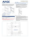
The MB-TP15 Universal VESA Mounting Kit (FG032-50) allows the 15" Modero
touch panels to be mounted on a pivot/pitch, extendable arm, pole, ceiling,
under-cabinet mount, or any other variation of VESA-compliant mounting
hardware.
Universal VESA Mounting Box for 15" Modero Panels
5.
Remove the Connector Overlay from the back box housing.
6.
Remove the four pan-head housing screws from the rear of the NXD
unit (FIG. 2). These screws secure the back box to the internal panel
casing.
The MB-TP15 kit includes everything the installer needs to mount a 15” Modero
panel (wall mount version) to any standard 75mm x 75mm VESA mounting
hardware (purchased separately). The kit includes a metal back box, a plastic
rear cover (with cable routing hole (which accepts the included strain-relief
grommet) and other required hardware (see Specifications table for details). .
Vents
front
DO NOT
REMOVE
these
(panel
securing)
screws
DO NOT
REMOVE
these
(panel
securing)
screws
Unscrew these
4 pan-head Housing
screws to remove the
back box
Cable routing hole
(accepts Strain Relief Grommet)
FIG. 2 Location of the attachment screws on the NXD back box
7.
75mm x 75mm
VESA mounting configuration
Lift the back box housing to separate it from the internal panel casing.
Note: Do not remove the four panel securing screws. These screws secure the
LCD to the metal casing.
Installing the MB-TP15 Back Box
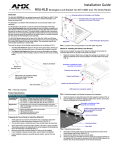
FIG. 1 MB-TP15 Universal VESA Mounting Box and Rear Cover (rear view)
Specifications
1.
Unscrew the four pan-head Housing screws (#8-32) from the
MB-TP15 rear plastic cover.
2.
Gently place the MB-TP15 back box over the internal panel casing
(with the cable routing hole on the right-side of the panel).
3.
Re-install and secure the four pan-head Housing screws into their
pre-drilled holes along the edges of the MB-TP15 back box (FIG. 2)
and secure them using a grounded Phillips-head screwdriver.
4.
Replace the Connector Overlay back over the connector opening and
align the connector locations.
5.
Re-secure the metal connector overlay (using a grounded
Phillips-head screwdriver) and re-secure the nut on the headphone
jack.
MB-TP15 Specifications
MB-TP15 Mounting Kit Installed Dimensions
(HWD):
• 14.37" x 15.19" x 3.59" (36.50 cm x 38.59 cm x 9.12 cm)
Operating /Storage
Environments:
•
•
•
•
Operating Temperature: 0° C (32° F) to 40° C (104° F)
Operating Humidity: 20% - 85% RH
Storage Temperature: -20° C (-4° F) to 60° C (140° F)
Storage Humidity: 5% - 85% RH
Included Accessories
• Black metallic VESA back box (62-0032-50)
• Black plastic cover (with grommet opening) (60-0032-50)
• Four Phillips pan-head screws (#8-32 x 0.50 Black)
(80-0146-02)
• Tie Wrap (Large) (45-0009A) (for use with NXA-MTC/RGB)
• Twelve Under-cut Phillips-head screws (#6-32 x 0.500 Black)
(80-0139)
• Strain relief grommet (45-0004-03) (for use with CA2250-50)
• Universal VESA Msount grommet (45-0032-01)
(for use with NXA-MTC/RGB)
Overview - Installing the MB-TP15 Kit
Cable Installation for the MB-TP15 Back Box
1.
Connect the cable connectors (RJ-45, Ethernet, and any other
audio/video wiring) to their respective locations on the side of the
touch panel.
2.
Use the tie-wrap (45-0009A) to wrap the cables together inside the
VESA Mount enclosure. This cable tie is used to insure the cable will
not pull through or work itself through the new larger strain relief
grommet (45-0032-01) over time.
Upgrading the original Modero back box with the MB-TP15 Universal VESA
Mounting Kit involves three main processes:
•
Removing the original Modero back box, and installing the new
MB-TP15 back box.
3.
•
Threading cables through the strain relief grommet opening in the rear
plastic cover.
Thread the incoming cables through the hole on the rear plastic cover
and then through the strain relief grommet.
4.
•
Finalizing the installation of the NXD (with MB-TP15 back box and
cables) into the plastic cover, securing both components, and finalizing
the strain relief grommet installation.
Slide the grommet along the cable and securely insert it into the
opening on the rear plastic cover (FIG. 4).
Finalizing the Installation
1.
Gently place the rear plastic cover over the NXD panel (with LCD and
MB-TP15 back box).
2.
Insert the protruding cables, coming out from the opening on the rear
plastic cover, into the open strain relief grommet.
3.
Allow some slack/length on these cables as a service loop. This service loop provides enough cable length so you can later remove the
NXD (with connected cables) from the rear plastic cover.
Removing the Original Modero Back Box
1.
Detach all connectors from the side of the touch panel.
2.
Remove the magnetic faceplate from the NXD unit by carefully gripping the faceplate and pulling outwards.
3.
Place the LCD face-down on a soft cloth to expose the bottom of the
panel and prevent scratching of the LCD.
4.
Using a grounded Phillips-head screwdriver, remove the two screws
on either side of the metal connector overlay, and remove the headphone nut from the headphone jack.
Caution: Verify that the Strain Relief Grommet is securely closed over the
cables and the clip is facing the correct direction (upwards). The process
of securing the strain relief grommet may require the use of pliers. Also
verify the length and location of the inserted cables. once the strain relief
grommet is closed, it is difficult to re-open.
4.
Carefully apply pressure to close the strain relief grommet over the
desired cable location.
5.
Firmly push the strain relief grommet into the opening (toward the
inside) until the rim is securely flush against the back of the rear plastic cover (FIG. 4).
6.
Securely grasp both sides of the NXD panel (with LCD, MB-TP15
back box, and attached cables), rotate the entire unit over, and lie it
on a flat level surface.
7.
Note the available mounting contact surface area on the rear plastic
cover (FIG. 3). This area represents the space available for use with
a VESA connector plate.
8.
Insert and secure the twelve #6-32 securing screws into their
pre-drilled holes along the edges of the NXD unit (FIG. 4). This step
secures the NXD unit to the rim of the rear plastic cover.
9.
Align a VESA mount connector (purchased separately) to the four
#8-32 screw holes on the back of the rear plastic cover (FIG. 4).
11. Secure these four #8-32 screws to the rear plastic cover by using a
grounded Phillips-head screwdriver. This step secures the VESA
mount to the rear of the panel.
Refer to your particular VESA mount manufacturer’s installation
procedures for further surface mounting procedures.
.72[18MM]
3.83[97MM]
3.23[82MM]
10. Insert the four provided #8-32 screws through the VESA mount’s four
holes and then into the pre-drilled holes on the rear plastic cover.
Note: When installing a VESA mount to the rear plastic cover, use only
the AMX provided #8-32 screws.
4.52[115MM]
FIG. 3 MB-TP15 Mounting contact surface area
DO NOT REMOVE
Twelve
#6-32
securing
screws
Connector
Opening
MB-TP15 back box
(62-0032-50)
Strain relief grommet (Clip facing up)
Rim of the strain relief grommet
should lie flush against enclosure
Internal panel casing
Securing
hole locations
(3 on each side)
Route cabling
through the
Strain Relief
Grommet
Four (pan-head) Housing Screws
Rear plastic cover
(60-0032-50)
Four (#8-32) screws
FIG. 4 Location of the attachment screws on the NXD back box
AMX Corporation reserves the right to alter specifications without notice at any time.
For full warranty information, refer to the AMX Instruction Manual(s) associated with your Product(s).
036-004-2785 12/05 ©2005
AMX Corporation. All rights reserved. The AMX logo is a trademark of AMX Corporation. AMX reserves the right to alter specifications without notice at any time.
3000 RESEARCH DRIVE, RICHARDSON, TX 75082 • 800.222.0193 • fax 469.624.7153 • technical support 800.932.6993 • www.amx.com
93-0032-50
REV: C