1
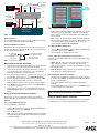
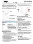
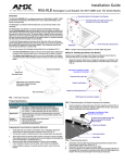
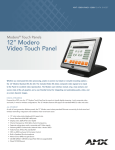
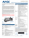
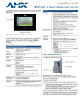
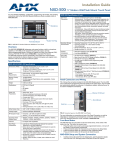
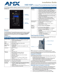
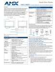
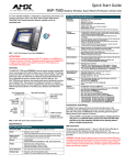
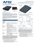
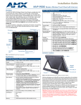
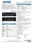
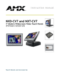
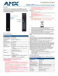
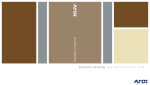
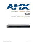
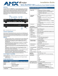
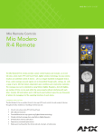
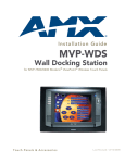
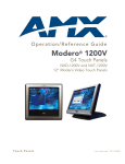
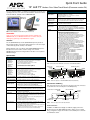
Quick Start Guide
12" and 15"
Modero Color Video Touch Panels (Firmware version G4)
For more detailed installation, configuration, programming, file transfer, and
operating instructions, refer to the 12" and 15" Modero Touch Panel Series
Instruction Manual, available on-line at www.amx.com.
NXD panel
(Wall Mount)
NXT panel
(Table Top)
FIG. 1 Sample Wall Mount and Table Top CV Touch Panels
Modero CV Specifications (Cont.)
Operating /Storage
Environments:
•
•
•
•
NXA-AVB:
A/V Breakout Box:
FG2254-01 (FIG. 2)
• Included accessory with CV12 and CV15 panels
• Provides video/audio distribution to the A/V panel over CAT5 cable
(up to 200’/60.96 m) and accepts either Composite or S-Video
Supported Audio
Sample Rates:
• 48000Hz, 44100Hz, 32000Hz, 24000Hz, 22050Hz, 16000Hz,
12000Hz,11025Hz, and 8000Hz.
Included
Accessories:
• Installation Kit for 12"/15" panels (KA2250-02):
- One 2-pin mini-Phoenix connector (41-5025) and
- Three Phillips-head screws (#4-20 x 0.250 Black) (80-0114-08)
• Modero Table Top Cable (CA2250-50) provided with all NXT panels.
Optional
Accessories:
• CB-TP12 Conduit/Wallbox (FG031-10)
• CB-TP15 Conduit/Wallbox (FG032-10)
• MB-TP12 Universal VESA Mounting Box (FG031-50):
- One strain relief grommet (45-0004-03)
- One black metallic VESA back box (62-0031-50)
- One black plastic cover (with grommet opening) (60-0031-50)
- Four Phillips pan-head screws (#8-32 x 0.50 Black) (80-0146-02)
- Twelve Phillips-head screws (#6-32 x 0.500 Black) (80-0139)
• MB-TP15 Universal VESA Mounting Box (FG032-50):
- One strain relief grommet (45-0004-03)
- One black metallic VESA back box (62-0032-50)
- One black plastic cover (with grommet opening) (60-0032-50)
- Four Phillips pan-head screws (#8-32 x 0.50 Black) (80-0146-02)
- Twelve Phillips-head screws (#6-32 x 0.500 Black) (80-0139)
• NXA-BASE/B Battery Base Kit (FG2255K)
1 battery base (FG2255) and 2 NXT-BP batteries (FG2255-10)
• NXA-RK12 Rackmount kit for 12" Wall Mount panels (FG2904-50)
• NXA-RK15 Rackmount kit for 15" Wall Mount panels (FG2904-51)
• NXA-WC80211b, 802.11B Wireless Card (FG2255-02)
• NXT-CHG Kit (FG2250-50K):
1 charger (FG2250-50) and 2 NXT-BP batteries (FG2255-10)
• PSN4.4 Power Supply (12 VDC) (FG423-45)
• PSN6.5 Power Supply (12 VDC) (FG423-41)
• Upgrade SDRAM memory:
NXA-EXM128M - 128 MB memory card (FG079-01)
NXA-EXM256M - 256 MB memory card (FG079-02)
• Upgrade Compact Flash (factory programmed with firmware):
NXA-CFTP128M - 128 MB compact flash card (FG2116-22)
NXA-CFTP256M - 256 MB compact flash card (FG2116-23)
NXA-CFTP512M - 512 MB compact flash card (FG2116-24)
NXA-CFTP1GB - 1 GB compact flash card (FG2116-25)
ATTENTION!
Verify you are using the latest NetLinx Master Firmware (available from
www.amx.com) on your ME260/64 and NI-Series Controllers. Verify the
TPDesign4 program being used is Version 2.4 or higher.
Overview
The 12" (NXT/NXD-CV12) and 15" (NXT/NXD-CV15) Video panels are
4th generation graphics touch panels that provide richer colors and crisper
contrast than any panels currently on the market.
Modero tilt panels now come with an optional NXA-BASE/B battery base
that allows it to function off the collective charge of two internal
NXT-BP batteries that can be charged either in the base or in an optional
NXT-CHG charger.
Specifications
Modero CV Specifications
Dimensions (HWD):
NXT-CV15
(FG2252-11)
NXD-CV15
(FG2253-12)
CB-TP15
(FG032-10)
• 12.94" x 14.95" x 11.73" (32.87 cm x 37.97 cm x 29.78 cm)
Fully lowered height: 7.45" (18.92 cm)
• Decor faceplate included: 14.37" x 15.20" x 3.31"
(36.50 cm x 38.61 cm x 8.40 cm)
• Conduit/wallbox: 13.48" x 14.18" x 3.49"
(34.24 cm x 36.00 cm x 8.85 cm) (optional)
Dimensions (HWD):
NXT-CV12
(FG2250-11)
NXD-CV12
(FG2251-12)
CB-TP12
(FG031-10)
• 10.91" x 12.34" x 12.50" (27.70 cm x 31.33 cm x 31.75 cm)
Fully lowered height: 6.77" (17.20 cm)
• Decor faceplate included: 12.38" x 12.59" x 3.25"
(31.43 cm x 31.97 cm x 8.25 cm)
• Conduit/wallbox: 11.52" x 11.60" x 3.50"
(29.27 cm x 29.47 cm x 8.89 cm) (optional)
Power Requirements
(CV12):
• Constant current draw: 2.04 A @ 12 VDC (stand-alone)
• Startup current draw: 3.0 A @ 12 VDC (stand-alone)
Power Requirements
(CV15):
• Constant current draw: 3.45 A @ 12 VDC (stand-alone)
• Startup current draw: 5.1 A @ 12 VDC (stand-alone)
Minimum power
supply required:
• CV12: requires a PSN4.4 Power Supply (FG423-45)
- using accessories can increase the power draw requirements
• CV15: requires a PSN6.5 Power Supply (FG423-41)
- using accessories can increase the power draw requirements
Memory:
• 64 MB SDRAM (upgradable to 256 MB)
• 64 MB Compact Flash (upgradable to 1 GB factory programmed)
Resolutions:
• 12" panels: 800 x 600 pixels
• 15" panels: 1024 x 768 pixels
Front Panel:
• Light Sensor: Photosensitive light detector for automatic adjustment of
the panel brightness
• Motion Sensor (PIR): Proximity Infrared Detector to wake the panel
when panel is approached
• Sleep Button: Pushbutton (grey) used to either put the panel into a
"sleep" or "wake" state
• Microphone: Used for intercom applications
• Speakers: Frequency response 450 Hz - 7 KHz
Rear Connectors:
• PCMCIA Card Slot: Provides wireless connectivity (with upgrade)
• Stereo Ouput Connector: Stereo output through a 3.5mm mini-jack
(for use with external speakers or headphones)
• Audio/Video Connector: RJ-45 connection for A/V signals between the
NXA-AVB Breakout Box and the panel
• Ethernet 10/100 Port: RJ-45 port for 10/100 Mbps communication
• ICSNet Connector: RJ-45 connection for ICSNet interface
Operating Temperature: 10° C (50° F) to 40° C (104° F)
Operating Humidity: 20% - 85% RH
Storage Temperature: -20° C (-4° F) to 60° C (140° F)
Storage Humidity: 5% - 85% RH
NXA-AVB A/V Breakout Box
FIG. 2 shows the front and rear connectors on the Breakout Box.
Composite/
S-Video
Luma
S-Video Chroma
ICSNet (to panel)
(front)
Power In
(rear)
Audio
In
Mic Out
ICSNet In
Power (to panel)
Audio/Video
(to panel)
FIG. 2 Connector layouts on the NXA-AVB Breakout Box (included)
Connections and Wiring
FIG. 3 shows the layout of the connectors (located on the rear of the base
on the NXT and on the left side panel of the NXD panels).
Audio-Video from NXA-AVB
(CAT5)
Ethernet (CAT5)
A
ICSNet
(CAT5)
L
12VDC
AUDIO /
VIDEO
PCMCIA/
Cardbus slot
ETHERNET
10/100
Stereo Output
ICSNet
PWR
Power
FIG. 3 Connector layout on the CV Touch Panels
Power Connection
A PSN4.4 or PSN6.5 Power Supply can indirectly supply power to the
Modero panels via the NXA-AVB Breakout Box. FIG. 4 shows a sample
wiring configuration using both an indirect or direct PSN power connection
for a CV Modero Panel.
ICSNet In
(RJ-45)
Mic Out
(4-pin captive-wire)
Video In
(BNC)
PSN power
supply
Line Level out
(to amplifier
or VOL card)
Audio In
(6-pin captive-wire)
Master’s
connection
information
(front)
NXA-AVB
Breakout Box
PSN4.4/PSN6.5
supplied via
NXA-AVB box
(rear)
Direct
Connect
Ethernet
(CAT5)
ICSNet
(CAT5)
PSN power
supply
or
Audio/Video
(CAT5)
or
Panel’s connection information
NXD/T-CV12/15
Touch Panels
FIG. 6 Sample System Connection page
•
Listen - In this mode, add the Modero’s IP Address into the URL List
of the Master (using NetLinx Studio). This mode sets the Modero
panel to "listen" for broadcasts from the Master (using the panel IP
from its URL list).
•
Auto - In this mode, enter the System Number of the NetLinx Master.
This mode instructs the Modero to search for a Master that uses the
same System Number (assigned within the Master Connection
section) and that resides on the same Subnet.
FIG. 4 Sample Wiring configuration on CV Modero Panels
RJ-45 Connections
Use a standard CAT5 Ethernet cable to provide communication between
the touch panel, NXA-AVB, and the NetLinx Master.
Ethernet 10/100 Base-T Connector
The Ethernet cable (connected to the rear of the Table Top Panels or to
the side of the Wall Panel) provides 10/100 network connectivity between
the panel and the NetLinx Master.
A - Activity LED
(yellow) blinks
when receiving Ethernet
data packets.
L - Link LED (green) blinks
when the Ethernet cables
are connected and
terminated correctly.
To configure ICSNet Communication:
1.
Under the Master Connection column, toggle the ICSNET/Ethernet
field until the choices cycle to ICSNET.
2.
All other settings are disabled and do not apply.
Second - Setup the IP Settings (Panel Communication)
Toggle the on-screen DHCP/Static field to select the appropriate setting
for your system.
FIG. 5 Layout of Ethernet LEDs
Modero Setup and System Connection
1.
Carefully remove the panel from the shipping box, peel the protective
plastic cover from the LCD and apply power to the panel.
2.
From below the LCD, press the grey Front Setup Access button for 6
seconds (passing-over the Setup page) to access the Calibration
setup page and follow the on-screen instructions.
3.
Press the grey Firmware Setup Access button for 3 seconds to open
the Setup page and touch the on-screen Protected Setup button.
4.
Enter the panel password into the keypad. Factory default is 1988.
5.
•
DHCP - With this setting, other settings are greyed-out and do not
apply. Typically the Host Name can be left blank. These fields
(“pulled” from the Ethernet connection) are filled-in by the panel after
the unit is rebooted.
•
Static IP - With this setting, you must enter the network information
as provided by your Network Administrator.
Remaining System Connection Parameters
1.
Press the Device Number field to open the on-screen Device
Number keypad and enter a value for the panel (default is 10001).
Set the speed of the Ethernet connection to the panel by selecting
from either: Auto (default), 10 Half Duplex, 10 Full Duplex, 100 Half
Duplex, or 100 Full Duplex.
2.
6.
Press Done when finished and press the on-screen Reboot button
to cycle power to the panel.
Enter a valid username and/or password (if the target Master is
secured).
3.
7.
Repeat step 3 to access the Protected Setup page and touch the
System Connection button to open the System Connection page
(FIG. 6).
Press the Back button and then press the on-screen Reboot button
to save the changes and cycle power.
Setting up the System Connection Parameters
There are two choices for communication with the system Master:
Ethernet or ICSNet. The default method used for Master connection is
Ethernet.
NOTE: Press the on-screen Reboot button after any changes are
made to the touch panel’s Communication Parameters.
Setting up a Modero Wireless Connection
Refer to the 12" and 15" Modero Touch Panel Series Instruction Manual
for detailed wireless connectivity setup and configuration information.
First - Setup the Master Connection
To configure Ethernet communication:
1.
Under the Master Connection column, toggle the ICSNET/Ethernet
field until the choices cycle to Ethernet.
2.
Press the Mode button:
•
URL - In this mode, enter the System Number (zero for an unknown
System Number) and the IP/URL of the Master (Master Port Number
is defaulted to 1319).
AMX Corporation reserves the right to alter specifications without notice at any time.
For full warranty information, refer to the AMX Instruction Manual(s) associated with your Product(s).
036-004-2682 4/05 ©2005
AMX Corporation. All rights reserved. The AMX logo is a trademark of AMX Corporation. AMX reserves the right to alter specifications without notice at any time.
3000 RESEARCH DRIVE, RICHARDSON, TX 75082 • 800.222.0193 • fax 469.624.7153 • technical support 800.932.6993 • www.amx.com
93-2252
REV: H