1
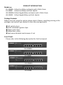
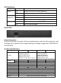
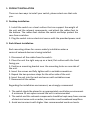
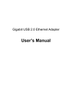
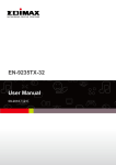
ES-1008PH / ES-1008P GS-1008PH / GS-1008P Quick Installation Guide 07-2012 / v1.0 COPYRIGHT Copyright Edimax Technology Co., Ltd. all rights reserved. No part of this publication may be reproduced, transmitted, transcribed, stored in a retrieval system, or translated into any language or computer language, in any form or by any means, electronic, mechanical, magnetic, optical, chemical, manual or otherwise, without the prior written permission from Edimax Technology Co., Ltd. Edimax Technology Co., Ltd. makes no representations or warranties, either expressed or implied, with respect to the contents hereof and specifically disclaims any warranties, merchantability, or fitness for any particular purpose. Edimax Technology Co., Ltd. reserves the right to revise this publication and to make changes from time to time in the contents hereof without the obligation to notify any person of such revision or changes. The product you have purchased and the setup screen may appear slightly different from those shown in this QIG. The specification is subject to change without notice. Please visit our web site www.edimax.com for the update. All brand and product names mentioned in this manual are trademarks and/or registered trademarks of their respective holders. Edimax Technology Co., Ltd. Add: No. 3, Wu‐Chuan 3rd Rd., Wu‐Ku Industrial Park, New Taipei City, Taiwan Tel: +886‐2‐77396888 Email: [email protected] PRODUCT INTRODUCTION Model no.: ES-1008PH: 8-Port Fast Ethernet Switch with 4 PoE+ Ports ES-1008P: 8-Port Fast Ethernet PoE+ Switch GS-1008PH: 8-Port Gigabit Ethernet Switch with 4 PoE+ Ports GS-1008P: 8-Port Gigabit Ethernet PoE+ Switch Package Contents Before you start using this switch, please check if there is anything missing in the package, and contact your dealer to claim the missing item(s): PoE switch x 1pcs Quick installation guide x 1pcs Power cord x 1pcs Rubber feet x 4pcs Rack-mount brackets and screws x 1 set Front Panel: Please refer to the following description for the front panel: ES-1008PH ES-1008P GS-1008PH GS-1008P LED Definitions: LED Name Light Status PWR On Off On LINK/ACT Off Flashing PoE On Off Description Switch on and correctly powered Switch not powered or not correctly powered Port is connected Port is not connected Port is active and transferring/receiving data PoE on and powering PoE/PoE+ PoE is not activated Back Panel: Power Connector: Plug in the female connector of the provided power cord into this connector, and the male into a power outlet. Supported input voltages range from 100-240V AC, and 50-60 Hz. Product Specifications: Model RJ-45 PoE MAC Address Buffer Memory Jumbo Frames Power budget Power Consumption Dimensions Weight Operating Temperature Storage Temperature Humidity ES-1008P GS-1008PH 8 ports 4 ports 8K 128KB 9KB 80W GS-1008P IEEE 802.3 10BaseT IEEE 802.3u 100BaseTX IEEE 802.3ab 1000BaseT IEEE 802.3af/802.3at PoE IEEE 802.3x Flow Control IEEE 802.3az Energy Efficient Ethernet 8 ports 8 ports 8 ports 8 ports 4 ports 8 ports 1K 96KB N/A 150W 80W 150W 5 Watts (Max) 266 x 184 x 44 x W x H) 1.95 kg 0 to 50℃ -40 to 70℃ IEEE 802.3 10BaseT IEEE 802.3u 100BaseTX IEEE 802.3af/802.3at PoE IEEE 802.3x Flow Control IEEE 802.3az Energy Efficient Ethernet Standards Interface ES-1008PH Operating:10 to 90% RH (non-condensing) 1. PRODUCT INSTALLATION There are two ways to install your switch, please select one that suits you. 2. Desktop Installation 1. Install the switch on a level surface that can support the weight of the unit and the relevant components, and attach the rubber feet to the bottom. The rubber feet cushion the switch and helps protect the case from scratches. 2. Plug the switch into an electrical source with the provided power cord. 3. Rack-Mount Installation Rack mounting allows for a more orderly installation when a series of network devices is being installed. 1. Disconnect all the cables from the switch. 2. Place the unit the right way up on a hard, flat surface with the front facing you. 3. Position a mounting bracket over the mounting holes on one side of the unit. 4. Insert the screws and fully tighten with a suitable screwdriver. 5. Repeat the two previous steps for the other side of the unit. 6. Insert the unit into the rack and secure with suitable screws 7. Reconnect all the cables. Regarding the installation environment, we strongly recommend: 1. The switch should be placed in an appropriately ventilation environment. A minimum 25 mm space around the unit is recommended. 2. The switch and the relevant components should be kept away from sources of electrical noise such as radios, transmitters and broadband amplifiers. 3. Avoid environments with higher than recommended moisture levels. Troubleshooting 1. Power LED is not lit Check if the power cord is properly connected to the plug and the power outlet; make sure the power cord is firmly plugged into the power socket of the switch. 2. LINK/ACT LED is not lit when connected to devices Make sure the network device attached to the switch is turned on. Make sure the network cable is properly connected to the switch and the network device. Make sure the network cable is a UTP cable that complies with EIA/TIA 568 and Category 5 specifications. Contact your dealer if problems persist. Federal Communication Commission Interference Statement This equipment has been tested and found to comply with the limits for a Class B digital device, pursuant to Part 15 of FCC Rules. These limits are designed to provide reasonable protection against harmful interference in a residential installation. This equipment generates, uses, and can radiate radio frequency energy and, if not installed and used in accordance with the instructions, may cause harmful interference to radio communications. However, there is no guarantee that interference will not occur in a particular installation. If this equipment does cause harmful interference to radio or television reception, which can be determined by turning the equipment off and on, the user is encouraged to try to correct the interference by one or more of the following measures: 1. Reorient or relocate the receiving antenna. 2. Increase the separation between the equipment and receiver. 3. Connect the equipment into an outlet on a circuit different from that to which the receiver is connected. 4. Consult the dealer or an experienced radio technician for help. FCC Caution This device and its antenna must not be co-located or operating in conjunction with any other antenna or transmitter. This device complies with Part 15 of the FCC Rules. Operation is subject to the following two conditions: (1) this device may not cause harmful interference, and (2) this device must accept any interference received, including interference that may cause undesired operation. Any changes or modifications not expressly approved by the party responsible for compliance could void the authority to operate equipment. CE Mark Warning This is a class B product. In a domestic environment this product may cause radio interference in which case the user may be required to take adequate measures.