1
STRIDER PLUS SERIES
3.2 Remote On/Off Controlled mode
The PSON# signal is required to remotely turn on/off the power supply,
PSON# is an active low signal that turns on the output power rails. When this is
not pulled low by the system, or left open, the outputs (except the +5VSB) turn off.
This signal is pulled to a standby voltage by a pull-up resistor internal to the power
supply.
TTL level
"H" 2.0 V - 5.25 V
"L" 0.0 V – 1.0 V
3.3 Regulation
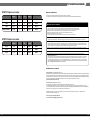
The cross regulation defined as follows, the output regulation should be within the
specified range.
Load
+5V
+3.3V
+12V
-12V
+5Vsb
Light Load.
2.54A
2.54A
7.96A
0.08A
0.49A
Typical Load
6.36A
6.36A
19.96A
0.2A
1.22A
Full Load
12.72A
12.72A
39.78A
0.41A
2.44A
3.4 Rise Time
DC output rise time is less than 20 mS at nominal line and full load.
3.5 Hold-up Time
DC +5V output maintains at least 12mS after power off which hold within para 3.1
under 230V/50Hz condition.
3.6 5VSB
5VSB is requierd for the implementation of PS-ON described above. 5VSB is a
standby voltage that may be used to power circuits that require power input
during the powered-down state of all power rails. The 5 VSB pin should deliver
5V ± 5% at a minimum of 3.0 A for PC board circuits to operate. Conversely,
PC board should draw no more than 3.0A maximum form this pin. This power may
be used to operate circuits such as soft power control.
03
3.7 PG-OK
PG-OK is a power good signal and should be asserted high by power supply to
indicate that the +5 VDC and +3.3 VDC outputs are above the under-voltage
thresholds of the power supply. When this signal is asserted high, there should
be sufficient mains energy stored by the converter to guarantee continuous
power operation within specification. Conversely, when either the +5VDC or the
+3.3VDC output voltage falls below the under-voltage threshold, or when mains
power has been removed for a time sufficiently long so that power supply
operation is no longer guaranteed, PG-OK should be deasserted to a low state.
See Figure 1 for a representation of the timing characteristics of the PG-OK,PS-ON,
and germane power rail signals.
3.8 3.3V Sense
A default 3.3V sense line should be implemented pin 13 of the connector.
3.9 Capacitive Load
The power supply should be able to power up and operate normally with the following
capacitances simultaneously present on the DC outputs.
Output
Capacitive load (uF)
+5V
6,000
+12V
8,000
+3.3V
6,000
-12V
350
+5VS
350
4.Protection
4.1 Input Protection
In primary circuit of the power supply , a protected fuse is inserted. Only internal fault
of the power supply will cause the fuse blown. Any overload or short circuit at DC
output will keep from fuse brown or fire hazard.
04