1
STRIDER PLUS SERIES
8. Product Safety
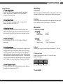
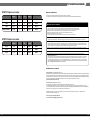
Time Diagram
Figure 1
8.1 Safety Requirement
AC ON
AC
8.2 Leakage Current
The AC leakage current is less than 3.5mA when the power supply connect
to 264Vac/50Hz .
AC OFF
+5Vs
PS-ON/OFF
POWER ON
POWER ON
4.75V
4.75V
8.3 Insulation Resistance
The insulation resistance should be not less than 30M ohm after applying of 500VDC
for 1 minute.
0.25V
+5V O/P
T4
T3
T5
T1
Power Good
8.4 Dielectric Voltage Withstand
The power supply shall withstand for 1 minute without breakdown the application of
a V AC voltage applied between both input line and chassis
(20mA DC cut-off current). Main transformer shall similarly withstand 3000Vac
applied between both primary and secondary windings for a minimum of one minute.
9. Power Good Signal
A TTL compatible signal for the purpose of initiating an orderly start-up procedure
under normal input operating conditions. During power up, this signal is asserted
( low ) until +5V is under regulation and AC reaches min. line specification range.
After all voltage are going appropriate level, the system may have a turn on delay
of 100mS, but no greater than 500mS. During power off the signal should go to low
level before +5V is out of regulation. The low level is 0 to 0.8V and high level is 4.75
to 5.25V. The " Power Good "signal can drive up to 6 standard TTL loads.
T2
T6
* T1 : Turn on time ( 2 sec. Max.)
* T2 : Rise time ( ≦ 20mS Max.)
* T3 : Power good turn on delay time ( 100 < T3 < 500 mS )
* T4 : Switch on time (0.5 sec. Max.)
* T5 : Power good turn off delay time ( 1.0 mS Min.) PS-ON/OFF
* T6 : Power hold-on time ( 12 mS Min.)
* Power on-off cycle :
When the power supply is turned off for a minimum of 2.0 sec. and turn on again,
the power good signal will be asserted.
10. MTBF
The MTBF of the power should be 100,000 hours min.
11. Burn-In
11.1 Input Voltage
Applying 220Vac for 230V model.
11.2 Test Condition
Applying 75% loads for the power supply in 45 (+/-5) oC chamber for 4 hours.
07
08