1
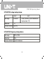
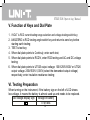
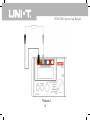
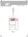
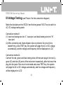
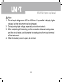
UT525/526
Electrical Testers
Operating Manual
UT525/526 Operating Manual
Contents
Item
I. Safety Precautions
Page
3
II. Features
7
III. Specifications
8
IV. Front View of the Instrument
14
V. Function of Keys and Dial Plate
16
VI. Testing Preparation
16
VII. Earth Testing 17
VIII. RCD Testing 19
IX. Voltage Testing
21
X. Insulation Resistance Testing
24
XI. Replace Battery 27
XII. Maintenance
29
1
UT525/526 Operating Manual
Overview
UT525/UT526 is a digital multi-functional electric testing instrument adopting
new design and integrating large scale analog integrated circuit, digital circuit
and microprocessor chips, which can mainly test parameters of residual current
device (RCD), earth, insulation resistance, DCV and ACV; with features of full
functions, high accuracy, stable performance, easy and reliable operation, it
is available to test RCD, insulation and earth of electric equipments. UT525/
UT526 is the ideal selection for repairing, maintaining and testing RCD of all
electric equipments.
2
UT525/526 Operating Manual
I. Safety Precautions
This instrument was designed, manufactured and tested according to
IEC61010 safety standard (Safety Requirements for Electrical Equipment).
This Instructions describe the warnings and safety rules which ensure the safe
operation and safe state of the instrument, which the user must follow. Please
read following instructions before using.
●
●
●
Warning
Please read and understood the Instructions before using.
Please follow the requirements of the Instructions, keep the
Instructions well for further reference at any time.
During testing, incorrect operation will cause accident and
instrument damage.
Sign
on the instrument tell the user that some operations should be
made according to relative requirements of the Instructions to ensure safety
operation of the instrument.
3
UT525/526 Operating Manual
Danger
It means under some conditions, the operation may cause
serious or fatal damages may be caused.
Warning It means taking care to keep away from electric shock.
It means avoiding instrument damage and gain accurate
Note
testing.
●
●
●
●
●
●
●
Danger
Do not test circuit with AC440V/DC440V or above.
Do not test in the place with inflammable conditions.
Do not operate the instrument if the surface of the instrument is wet or the
hand is wet.
During testing, do not touch the conductive part of the testing pen.
Do not open the battery cover during testing.
During testing insulation and RCD, do not touch the circuit to be tested.
Warning
When there is anything unusual to the instrument, such as the instrument
is damaged or the metal is exposed, please do not use it.
4
UT525/526 Operating Manual
●
●
●
●
●
●
●
●
Operate carefully under the voltage over 33Vrms, 46.7Vacrms or 70Vdc,
electric shock may be caused under such kind of voltage during operating.
After completing high resistance testing, the charge storage of the circuit
to be tested must be released.
Do not replace battery if the instrument is in place with humidity.
Make sure the all testing wires are connected with the testing ports firmly.
Before opening cover of the battery, please make sure the instrument is
turned off.
Note
Before testing resistance, the circuit to be tested must be discharged
completely and separated from the power circuit absolutely.
If the testing pen or adapter is damaged and needs to be replaced,
please replace with testing pen or adapter with the same model and
electric specifications.
When the battery sign (
) shows that the battery is used up, please do
not use the instrument any more. If the instrument won’t be used for a long
time, please take out the battery and then keep the instrument well.
5
UT525/526 Operating Manual
●
●
●
Do not put or use the instrument in the place with high temperature, high
humidity, inflammable or explosive matters and high electromagnetic field.
Do not clean the cover of the instrument with wet cloth of detergent, do not
use abrasives or solvent.
When the instrument is wet, please make it dry and then put it in the
proper place.
6
UT525/526 Operating Manual
II. Features
Danger of electric shock may happen
The instrument has double-insulation or reinforced insulation
DC
AC
Earth
●
●
●
Designed and manufactured strictly according to IEC61010 safety
standard, the instrument meets with Over Voltage Standard (CATIII600V)
and safety standard of Class II Pollution.
Auto discharge function.
Red warning light.
7
UT525/526 Operating Manual
III. Specifications
Error limit: ±(a% reading + digits), one year of warranty period
Environment temperature: 23±5℃
Environment humidity: 45-75%RH
UT525/UT526 RCD testing indexes
RCD testing current
Applied voltage
Accuracy tolerance
Testing time
range when
switch of
RCD is off Accuracy tolerance
10mA
30mA
100mA
300mA
Voltage: 220V±10%, frequency: 45Hz-65Hz
RCD testing current accuracy tolerance with AC (220V±2): (0+10%)
(10mA) range: 0-2,000mS
(30mA) range: 0-500mS
(100mA) range: 0-300mS
(300mA) range: 0-300mS
±(5%+2)
8
UT525/526 Operating Manual
UT525 earth testing indexes
Rated voltage
Test range
Test current
Accuracy tolerance
About 5.0V
0.01Ω-200Ω
>200mA for 0.00Ω-2.00Ω
0.01Ω-200Ω: ±(2%+5)
UT526 earth testing indexes
Rated voltage
Test range
Test current
Accuracy tolerance
About 5.0V
0.01Ω-2,000Ω
>200mA within 0.00Ω-2.00Ω
0.01Ω-2,000Ω: ±(2%+5)
9
UT525/526 Operating Manual
UT525 insulation resistance testing indexes
Rated voltage
100V
250V
Test range
0.05MΩ-200MΩ
Open circuit voltage DC 100V±10% DC 250V±10%
Rated test current 100KΩ load
250KΩ load
0.9mA-1.1mA
0.9mA-1.1mA
Short circuit
<1.8mA
Accuracy tolerance 0.05MΩ-200MΩ: ±(5%+5)
10
500V
DC 500V±10%
500KΩ load
0.9mA-1.1mA
UT525/526 Operating Manual
UT526 insulation resistance testing indexes
Rated voltage
250V
500V
Test range
0.05MΩ-200MΩ 0.05MΩ-300MΩ
Open circuit voltage DC 250V±10% DC 500V±10%
Rated test current 500KΩ load
1MΩ load
0.9mA-1.1mA
0.9mA-1.1mA
Short circuit
<1.8mA
Accuracy tolerance 0.05MΩ-500MΩ: ±(5%+5)
11
1,000V
0.05MΩ-500MΩ
DC 1,000V±10%
250KΩ load
0.9mA-1.1mA
UT525/526 Operating Manual
UT525/UT526 voltage testing indexes
Test range
DCV
±0-±440V
Resolution
1V
±(2%+3)
Accuracy tolerance
ACV
0-440 (50/60Hz), just for reference to
that less than 10V
UT525/UT526 frequency testing indexes
Test range
Resolution
Accuracy tolerance
20Hz-100Hz
1Hz
Just for reference
12
UT525/526 Operating Manual
●
●
●
●
●
●
●
●
●
●
●
●
Display: LCD display, max reading: 9999
Low battery voltage warning:
Over limit indication: “OL”
Auto range function
Unit display: can display function, electric unit signs
Work conditions: 0℃-40℃/ 85%RH or less
Storage condition: -20℃-60℃/90%RH or less
Dimensions: 150mm(L)×100mm(W)×71mm(D)
Current consumption: about 50mA (1,000V output) (about 10mA in general
condition)
Accessories: testing wire, alkaline battery (1.5V, AA)×6, Instructions,
carrying bag
Weight: 0.7kg (including batteries)
Power: alkaline battery (1.5V, AA)×6
13
UT525/526 Operating Manual
IV. Front View of the Instrument (see Picture 1)
1. L: jack of live wire terminal for RCD testing and positive terminal for voltage
testing
2. E: jack of earth for RCD testing
3. N: jack of null wire terminal for RCD testing and input negative terminal for
voltage testing
4. LINE: jack of high voltage output for insulation resistance testing
5. LCD
6. RCD current setup key and voltage testing switch key
7. RCD angles switch key and return-to-zero key
8. Test button
9. Dial plate
14
UT525/526 Operating Manual
Picture 1
15
UT525/526 Operating Manual
V. Function of Keys and Dial Plate
1. I/VOLT is RCD current testing range selection and voltage testing switch key;
2. ANG/ZERO is RCD testing angle switch key and return-to-zero key before
starting earth testing;
3. TEST is test key;
4. When dial plate points to Continuly, enter earth test;
5. When dial plate points to RCD/V, enter RCD testing and AC and DC voltage
testing;
6. When dial plate points to UT525 output voltage: 100V/250V/500V or UT526
output voltage: 250V/500V/1,000V (select the demanded output voltage)
respectively, enter insulation resistance testing;
VI. Testing Preparation
When turning on the instrument, if the battery sign on the left of LCD shows
low voltage, it means the battery is almost used up and needs to be replaced.
Low voltage display sign Voltage of battery
7V or less
16
UT525/526 Operating Manual
VII. Earth Testing (see Picture 2 for the connection diagram )
Connect the object to be tested with the instrument according to the diagram,
after that make the dial plate point to Continuly, and then press TEST key to
start earth test.
Note
1. To keep the accuracy of test, return-to-zero operation must be made (returnto-zero operation by pen: in state of earthing, make the two pens in reliable
short circuit state, after that press TEST key, and then press ANG/ZERO
return-to-zero key, the resistance of the pens will be clear to “0”, and the
LCD displays ZERO.
2. Do not test live object.
17
UT525/526 Operating Manual
Picture 2
18
UT525/526 Operating Manual
VIII. RCD Testing (see Picture 3 for the connection diagram)
Make the dial plate point to RCD/V and press I/VOLT key to set up test current
(test current: 10mA\30mA\100mA\300mA) to start RCD testing.
Connection Method:
Connect the red, green and blue testing wires of three-wire plug with the red
(L), green (E) and blue (N) ports respectively, and then insert the three-wire
plug into the 220V civil jack and press TEST key.
Note
1. During testing RCD, the earth terminal of power jack must be grounded
reliably.
2. During testing RCD, make sure that connection of L (live wire), N (null wire)
and E (earth wire) of power jack are connected rightly.
3. This testing is made under high voltage, pay attention to personnel safety
19
UT525/526 Operating Manual
Picture 3
20
UT525/526 Operating Manual
IX Voltage Testing (see Picture 4 for the connection diagram)
Make the dial plate point to RCD/V and the long press I/VOLT key to switch to
AC, DC voltage testing state:
Connection method 1:
(1) Insert red testing wire into “L” input port, and black testing wire into “N”
input port.
(2) After connecting red, black alligator clips or probes to the circuit to be
tested firmly, press TEST key, the system will judge the AC or DC voltage
automatically, and the voltage and frequency will be displayed on LCD.
Connection method 2:
Connect the red, green and blue testing wires of three-wire plug to the red (L),
green (E) and blue (N) ports of the instrument respectively, after that insert the
plug into the jack of the circuit to be tested and press TEST key, the system
will judge the AC or DC voltage automatically, and the voltage and frequency
will be displayed on LCD.
21
UT525/526 Operating Manual
Note
1. Do not input voltage over 440V or 440Vrms. It is possible to display higher
voltage, but the instrument may be damaged.
2. During testing high voltage, especially avoid electric shock.
3. After completing all the testing, cut the connection between testing wires
and the circuit tested, and dismantle the testing wires from input terminal
of the instrument.
4. When the battery cover is open, do not test.
22
UT525/526 Operating Manual
Picture 4
23
UT525/526 Operating Manual
X Insulation Resistance Testing (see picture 5 for the connection
diagram)
Note
1. Before testing, make sure that the circuit to be tested is uncharged, do not
test the insulation of charged equipment or live circuit.
2. When the battery cover is open, do not test.
3. Do not make the two pens short circuit state under high voltage input and
do not test the insulation resistance after outputting high voltage.
Press to make the dial plate point to UT525 (100V/250V/500V) or UT526
(250V/500V/1,000V)
1. Before testing insulation resistance, the circuit to be tested must be
discharged completely and separated from the power circuit absolutely.
2. Insert the red testing wire into “LINE” input terminal, and black testing wire
into “N” input terminal.
3. Connect the red, black alligator clips to the circuit to be tested, and the high
voltage is outputted from LINE terminal.
24
UT525/526 Operating Manual
Continuous Testing Operation
Select one test voltage with dial plate (the optional voltages of UT525:
100V/250V/500V; the optional voltages of UT526: 250V/500V/1,000V) and
press TEST key which is in self-locking state to make continuous testing and
output insulation resistance testing voltage, and the test light become red. After
completing testing, press TEST key to unlock to stop testing.
Note
1. Before testing, make sure that the circuit to be tested is uncharged, do not
test the insulation of charged equipment or live circuit.
2. After completing testing, do not touch the circuit with hand, the stored
electric capacity may cause electric shock.
3. Cut the connection between testing wires and the circuit tested, do not
touch them with hand until the voltage is released completely.
4. When the battery cover is open, do not test.
25
UT525/526 Operating Manual
Picture 5
26
UT525/526 Operating Manual
XI. Replace Battery (see Picture 6)
Note
1. Do not use old and new batteries at the same time.
2. Pay attention to the polarity during replacing battery.
Danger
1. To avoid potential electric shock, move the lead from the instrument before
replacing battery.
2. When the battery cover is open, do not test
3. When sign “
” is displayed on LCD, it means the battery needs to be
replaced, please operate as following:
1) Turn off the power (namely make the dial plate point to OFF), and move
testing wires away.
2) Loosen screw on the battery cover, and move away the battery cover,
and then replace the 6 batteries.
3) After replacing the batteries, make sure that the screw is tightened
firmly.
27
UT525/526 Operating Manual
Picture 6
28
UT525/526 Operating Manual
XII. Maintenance
Clear the shell
● Wipe the surface with soft wet cloth or sponge.
● To avoid instrument damage, do not dip the instrument into water.
● When the instrument is wet, make it dry and then store.
● When the instrument needs to be checked or repaired, please let
qualified professional maintenance man to repair or send it to the
designated maintenance point.
The content is subject to change without prior notice
29