1
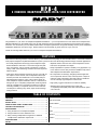
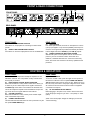
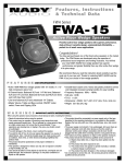
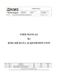
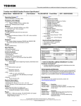
RACK GEAR
HPA-4
4 CHANNEL HEADPHONE/AMPLIFIER/LINE DISTRIBUTOR
HPA-4
4 CHANNEL HEADPHONE/AMPLIFIER/LINE DISTRIBUTOR
Congratulations on your choice of headphone/amplifier/line distributor — you have purchased one of the finest stereo headphone/amplifier/line distributors on the market today. This unit was developed using the expertise of professional sound engineers and working
musicians. You will find that your new NADY AUDIO HPA-4 has superior performance and greater flexibility than any other headphone/
amplifier/line distributors in its price range. Please read this manual carefully to get the most out of your new unit.
Thanks for selecting NADY AUDIO as your choice in headphone/amplifier/line distributor.
FEATURES
With extensive switching functions, extreme efficiency, and unmatched sound quality, the ultra-versatile HPA-4 is a universal 4-channel
multi-purpose headphone amplifier/line distribution system—perfect for the most demanding professional stage and studio applications.
• Separate Volume control for each channel adjusts the level to
both Phone and parallel Line outputs
• Four totally independent stereo high-power headphone amplifier/line distribution channels in a convenient single rack package—an ingenious, easy-to-operate unit allowing a maximum
variety of both useful monitoring and stereo line level signal distribution options.
• Easily expandable for optimum versatility in any application—up
to four HPA-4’s can be daisy chained for additional fully selectable headphone/line distribution requirements
• Input Source Select switches and Phone and Line 1/4" TRS stereo outputs on each channel, and 4 independent stereo input
sections (each with servo-balanced L & R 1/4"TRS jacks) enable independent selection of any of the 4 stereo signals for
each headphone amp/line distribution channel. This allows selecting from up to 4 completely independent monitor signals for
each set of headphones connected to the HPA-4 for optimum
monitoring flexibility or 4 separate choices for each channel’s
Line Output for enabling many useful, simple audio switching/
routing solutions.
• No-compromise circuit design, stringently selected tight-tolerance components and low-noise, extremely linear or amps for
reference-quality, transparent audio with maximum headroom
even at extremely high headphone volume levels
• High-quality, rugged construction for maximum reliability
• Shielded internal dual regulated power supply with
~115V(60Hz)/~230V(50Hz) select switch and fused IEC power
cord connector
TABLE OF CONTENTS
FEATURES ................................................................................. 2
WARNING ................................................................................... 3
Date of Purchase ____________________________________
INSTALLATION .......................................................................... 4
FRONT & REAR PANEL CONNECTIONS ................................ 5
Dealer’s Name ______________________________________
CONTROLS & INDICATORS ..................................................... 5
APPLICATIONS .......................................................................... 6
City _______________________________________________
1. Using the HPA-4 as a headphone amplifier .......................... 6
2. Using the HPA-4 as a line distribution unit ............................ 6
State _____________________ Zip _____________________
Model # ____________________________________________
3. Daisy chaining multiple HPA-4’s together for additional
headphone/line distribution requirements ............................. 6
Serial # ___________________
SPECIFICATIONS ...................................................................... 6
NOTES ........................................................................................ 7
2
WARNING
An equilateral triangle enclosing a lightening flash/arrowhead symbol is
intended to alert the user to the presence of uninsulated “dangerous
voltage” within the product’s enclosure which may be of sufficient
magnitude to constitute a risk of electric shock.
ATTENTION: RISQUE DE CHOC ELECTRIQUE NE PAS OUVRIR
An equilateral triangle enclosing an exclamation point is intended to alert
the user to the presence of important operating and service instructions in
the literature enclosed with this unit.
IMPORTANT SAFETY INSTRUCTIONS
When using this electronic device, basic precautions should always be taken, including the following:
1.
Read all instructions before using the product.
2.
Do not use this product near water (e.g., near a bathtub, washbowl, kitchen sink, in a wet basement, or near a swimming
pool, etc.).
3.
4.
This product should be used only with a cart or stand that will keep it level and stable and prevent wobbling.
This product, in combination with headphones or speakers, may be capable of producing sound levels that could cause
permanent hearing loss. Do not operate for a long period of time at a high volume level or at a level that is uncomfortable.
If you experience any hearing loss or ringing in the ears, you should consult an audiologist.
5.
6.
The product should be positioned so that proper ventilation is maintained.
The product should be located away from heat sources such as radiators, heat vents, or other devices
(including amplifiers) that produce heat.
7.
The product should be connected to a power supply only of the type described in the operating instructions or as marked on the
product. Replace the fuse only with one of the specified type, size, and correct rating.
8.
The power supply cord should: (1) be undamaged, (2) never share an outlet or extension cord with other devices so that the
outlet’s or extension cord’s power rating is exceeded, and (3) never be left plugged into the outlet when not being used for
a long period of time.
9.
Care should be taken so that objects do not fall into, and liquids are not spilled through, the enclosure’s openings.
10. The product should be serviced by qualified service personnel if:
A.
The power supply cord or the plug has been damaged.
B.
Objects have fallen into, or liquid has been spilled onto the product.
C.
The product has been exposed to rain.
D.
The product does not appear to operate normally or exhibits a marked change in performance.
E.
The product has been dropped, or the enclosure damaged.
11. Do not attempt to service the product beyond what is described in the user maintenance instructions. All other servicing should
be referred to qualified service personnel.
3
INSTALLATION
To ensure years of enjoyment from your NADY AUDIO HPA-4, please read and understand this manual thoroughly before
using the unit.
INSPECTION
Your HPA-4 was carefully packed at the factory in packaging designed to protect the units in shipment. Before installing and using your
unit, carefully examine the packaging and all contents for any signs of physical damage that may have occurred in transit.
(Note: Nady Systems is not responsible for shipping damage. If the unit is damaged, do not return to us, but notify your dealer and the
shipping company immediately to make a claim. Such claims must be made by the consignee in a timely manner.)
CONTENTS:
• Instruction manual
• HPA-4 (verify that the unit’s serial number is same as shown on shipping carton)
• AC Power cord
• Warranty Card
RACK MOUNTING
The HPA-4 fits into one standard 19" rack unit of space (1 3/4"). Parts of the unit can become very warm during use. This is normal
during operation. Care should be taken to ensure that there is enough space around the unit for cooling (at least 12” or 30cm). Do not
place the HPA-4 on high temperature devices such as power amplifiers, etc., or the unit may overheat in operation. Also, do not place
the unit on speakers as this may cause them to move and/or fall due to speaker vibrations.
Although the unit’s chassis is shielded against radio frequency (RF) and electromagnetic interference (EMI), extremely high fields of RF
and EMI should be avoided.
POWER CONNECTION
The HPA-4 has an internal power supply and is designed to operate from an external AC source. Power requirements for electrical
equipment differ from area to area. Be sure to confirm that the voltage selected by the voltage selector switch on the back panel is
proper for your area (120VAC/60 Hz or 230VAC/50Hz) per the information below:
Europe (except UK): 230V, 50Hz
UK and Australia: 240V, 50Hz
USA and Canada: 120V, 60 Hz
For other areas, please check with local authorities.
When ready to operate, plug the AC cord into the power source. Make sure that the unit is turned off before connecting to the AC
power source to avoid possible loud transients which can damage your speakers or your ears, especially when monitoring with
headphones.
4
FRONT & REAR CONNECTIONS
(5)
(4)
(6)
FRONT PANEL
(1)
(2)
REAR PANEL
(8)
(9)
(7)
(3)
FRONT PANEL
REAR PANEL
(1)
STEREO HEADPHONE OUTPUTS
Four stereo 1/4” output jacks for connecting four stereo headphones
(2)
DIRECT LINE DISTRIBUTION OUTPUTS
Four stereo 1/4” line level output jacks for use for line distribution
(3)
AUDIO INPUTS
Four stereo-pair balanced, line level 1/4” TRS jacks for 4 stereo
(L & R) input signals. If only the LEFT (MONO) channel input is
used, the mono signal will be provided automatically at both the
Left and Right sides of the PHONE (1) and LINE (2) outputs.
(8)
POWER CONNECTOR WITH FUSE HOLDER
Standard IEC power cord receptacle used to connect the AC
power to your unit. It features a built-in fuse holder for a
5X20mm, 0.5A/250V slow-blow fuse. If the fuse continuously
blows, shut off the unit and have it serviced by qualified service
personnel.
CONTROLS & INDICATORS
FRONT PANEL
REAR PANEL
The HPA-4 has four independent headphone amplifiers or line
distribution channels. The unit provides 2 rotary controls and 2
stereo jacks per channel.
(4)
INPUT SIGNAL SOURCE SELECT SWITCHES
Each channel features a rotary selector switch which allows you
to select any of the 4 stereo input source signals connected to
the INPUTS (3) of the HPA-4 to be routed to the selected channels of the headphone amplifier and line distribution output. Simply choose the source signal desired for that channel.
(5)
VOLUME CONTROLS
Each channel features a rotary volume pot for variable adjustment of the desired output level.
(6)
POWER LED INDICATOR
This LED indicator illuminates when the unit is powered on by the
rear panel POWER SWITCH (7).
(7)
POWER SWITCH
To turn the unit ON or OFF, press the upper or lower portion of
this button as indicated. The front panel POWER LED INDICATOR (6) will illuminate when the power is “ON”. Before turning on
this unit, verify connection to the proper voltage AC source, check
all connections and turn down the level controls of equipment
connected to the outputs.
(9)
AC VOLTAGE SELECTOR SWITCH
Before plugging in the power cord, check to see that the unit is
set for the proper voltage for your area: ~115v (60Hz) or ~230V
(50Hz).
(Note: use at the improper voltage can damage your unit and
void the warranty.)
5
APPLICATIONS
USING THE HPA-4 AS A HEADPHONE AMPLIFIER
Connect a stereo (L & R) program source (2 x 1/4” plugs) to the rear of the HPA-4 using one of the available 4 x stereo INPUT (3)
pairs on the rear panel.
Connect a set of headphones using a stereo 1/4” cable to any of the HEADPHONE OUTPUTS (1) on the front panel of the HPA-4.
Select the source signal from the rotary SELECTOR (4) switch for the channel in use. Set to an appropriate level for monitoring.
(Note: If only the LEFT (MONO) channel input is used, the mono signal will be provided automatically at both the Left and Right sides
of the PHONE (1) and LINE (2) outputs.)
Since the HPA-4 offers four independent channels, you can have four individual mixes for four musicians with a single unit. In studio
recording applications, you can configure sub-groups, aux sends or single outputs of your audio mixer to feed signals independently to
the HPA-4. This enables each musician to receive a specific configuration of instruments of their choice
in their headphones.
[Note - If four headphone outputs are not enough, you can interface and link any number of HPA-4’s for additional outputs (see below).]
USING THE HPA-4 AS A LINE DISTRIBUTION UNIT
To use the HPA-4 as a line distribution unit all you have to do is use the line output instead of the headphone output on the front of the
unit for the line distribution signal feed. All other operation is identical as using the unit as a headphone amplifier.
Daisy chaining multiple HPA-4’s together for additional headphone/line distribution requirements.
It is very easy to chain multiple HPA-4’s together. Use appropriate single stereo 1/4” TRS to two 1/4” TS (2 x mono) adapter cables
and make connections from the LINE DISTRIBUTION OUTPUT (2) channels on the front of your first HPA-4 unit to the stereo (L&R)
AUDIO INPUTS (3) on the rear of your second HPA-4.
This effectively allows an additional (fully selectable) 4 headphone outputs and an additional 4 line outputs! You can continue to chain
up to four HPA-4 units together using this same procedure.
SPECIFICATIONS
FUNCTION CONTROLS
Volume ........................................................ Per channel, variable
Signal selectors .......................................... Per channel, Variable
AUDIO INPUTS
Connectors ...................................................................... 1/4" jack
Type .......................................................................... Unbalanced
Impedance ................................................................... 47k Ohms
Peak input level .................................................................. +25dB
Gain control range ............................................................. +35dB
POWER SUPPLY
AC requirements ............................... Selectable, ~100-120 VAC,
~ 200-240V AC, 50-60 Hz
Power consumption .......................................................... 11.5VA
Fuse ...................................... 100-120 VAC: 630 mA (slow-blow)
200-240 VAC: 315 mA (slow-blow)
100-240 VAC: 500 mA (slow-blow)
5X20mm glass type
Power cord connector ........................... Standard IEC receptacle
with built-in fuse holder
HEADPHONE POWER AMPLIFIER OUTPUTS
Max.output level ....... 300mW@32 Ohms (max 1W @ 32 Ohms)
Output impedance .......................................................... 22 Ohms
Max. gain .......................................................................... +20 dB
LINE DISTRIBUTION OUTPUTS
Connectors ...................................................................... 1/4" jack
Type ............................................................. Unbalanced/Parallel
PHYSICAL
Dimensions ..................... 1.75"X 19"X 8.5"(44.5X482.6X217mm)
Weight ................................................................ 6.93lbs (3.15Kg)
DISTORTION, FREQUENCY RESPONSE,
S/N RATIO & CROSSTALK
Distortion ............................................................................ 0.02%
Frequency response ................................ 20Hz~20kHz, 0dB~-2B
S/N Ratio ........................................................... Better than 80dB
Crosstalk rejection ............................... >68dB@1kHz; 20dBinput
The specifications above are correct at the time of printing of this manual. For improvement purposes, all specifications for this unit,
including design and appearance, are subject to change without prior notice.
6
NOTES
7
SERVICE INFORMATION
In the U.S. If you are experiencing operational problems with your system, please refer to the Support page at www.nady.com for assistance.
Should your wireless system require service, please contact the Nady Service Department at (510) 652-2411 to obtain a Return Authorization (R/A)
Number and service quote (if out of warranty). Make sure the R/A Number is clearly marked on the outside of the package that you are returning.
If your unit is out of warranty, please enclose a cashier’s check or money order (or pay by credit card) per instructions by the Nady Service Department. Ship your unit prepaid to: Nady Systems, Service Department, 6701 Shellmound Street, Emeryville, CA 94608. Include a brief description of
the problem you are experiencing. For service of a unit under warranty, please follow the instructions in the following section.
Outside the U.S. For service, please contact the NADY distributor in your country through the dealer/store from which you purchased this product.
Do not attempt to service this unit yourself asit can be dangerous and will also void the warranty.
ONE-YEAR LIMITED WARRANTY
Nady Systems, Inc. warrants to the original consumer purchaser that the unit is free from any defects in material or workmanship for a period of
one year from the date of original retail purchase. If any such defect is discovered within the warranty period, Nady Systems, Inc. will repair or
replace the unit free of charge, subject to verification of the defect or malfunction upon return to Nady Systems. Please do not return your Nady
product to the store where it was purchased as Nady Systems handles your warranty service directly. Communication with our Service Department is the most efficient means of servicing your unit and we are dedicated to keeping you a satisfied customer.
To the extent permitted by law, any applicable implied warranties, including warranties of merchantability and fitness are hereby limited to one year
from the date of purchase. Consequential or incidental damages resulting from a breach of any applicable express or implied warranties are
hereby excluded. This warranty is in lieu of all other agreements and warranties, general or special, express or implied and no representative or
person including a Nady dealer, agent, or employee is authorized to assume for us any other liability in connection with the sale or use of this
Nady Systems’ product.
Whereas some states do not allow limitations on how long implied warranties last, and do not allow exclusion of incidental or consequential
damages, the above limitations and exclusions may not apply to you. This warranty gives you specific legal rights and you may also have other
rights which may vary from state to state.
This warranty is subject to the following conditions:
1) This system must have been purchased from an authorized Nady dealer and all warranty service must be performed by Nady’s service
department. Any service not performed by Nady will automatically void this warranty.
2) Items not covered: physical damage resulting from improper handling of the unit in transit from the factory by the shipper (Nady Systems is not
responsible for such damage and all such claims must be made against the shipping company by the consignee); defects caused by normal wear
of the product (expendable parts are typically connectors, cables, potentiometers, switches and similar components); damage or defects caused
by abuse, neglect, accident, failure to connect or operate the unit in any way that does not comply with applicable technical or safety regulations,
or improper repair, excessive heat or humidity, alteration or unreasonable use of the unit, causing cracks, broken cases/housings or parts; damage
caused by leaking batteries; finish or appearance items; items damaged in shipment en route to Nady Systems, Inc. for repair. The warranty is null
and void if any Nady serial number has been removed or defaced.
How To Obtain Service:
1) If factory service is required, please contact our Service Department at (510) 652-2411 for a return authorization (R/A) number. Make sure the
R/A number is clearly marked on the outside of your package. (Please note: if an R/A number is not included, our Shipping Department cannot
accept your package.)
2) Send the unit back to Nady Systems, 6701 Shellmound Street, Emeryville, CA, 94608, freight pre-paid. You must include proof of date and
place of purchase (i.e., photocopy of your bill of sale) or Nady cannot be responsible for repair or replacement. Nady Systems, Inc. will not repair,
nor be held responsible, for any units returned without proper identification, return address, and R/A number clearly marked on the package.
3) Per the above, Nady will perform all warranty service and return the unit to you at no charge. Nady Systems will inform the buyer if product sent
in does not meet the terms of this warranty and will provide a quote for fixing the unit and/or shipping it back exclusively at the buyer’s expense.
NADY SYSTEMS, INC. • 6701 SHELLMOUND STREET, EMERYVILLE, CA 94608
Tel: 510.652.2411 • Fax: 510.652.5075 • nady.com