1
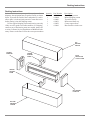
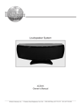
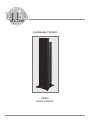
Loudspeaker System
XR200
Owner’s Manual
McIntosh Laboratory, Inc.
2 Chambers Street Binghamton, New York
13903-2699 Phone: 607-723-3512
www.mcintoshlabs.com
WARNING - TO REDUCE RISK OF
FIRE OR ELECTRICAL SHOCK, DO
NOT EXPOSE THIS EQUIPMENT TO
RAIN OR MOISTURE.
NO USER-SERVICEABLE PARTS
INSIDE. REFER SERVICING TO
QUALIFIED PERSONNEL.
To prevent the risk of electric shock, do not remove cover or
back. No user-serviceable parts inside.
IMPORTANT SAFETY
INSTRUCTIONS!
PLEASE READ THEM BEFORE
OPERATING THIS EQUIPMENT.
1. Read these instructions.
2. Keep these instructions.
3. Heed all warnings.
4. Follow all instructions.
5. Do not use this apparatus near water.
6. Clean only with a non-abrasive dry soft cloth.
7. Install in accordance with the manufacturer’s
instructions.
8. This Loudspeaker is capable of producing
extremely high sound pressure levels, even
when connected to amplifiers of moderate
power output. User caution is advised. Ear
protection is recommended when playing at
high volumes as continued exposure to high
sound pressure levels can cause permanent
hearing impairment or loss. The use of a
Sound Level Pressure Meter will greatly aid
in determining when high volume levels are
occurring.
9. Do not install near any heat sources such as
radiators, heat registers, stoves, or other apparatus
(including amplifiers) that produce heat.
10. Only use attachments/accessories specified by the
manufacturer.
11. Use only with the cart, stand, tripod, bracket, or
table specified by the manufacturer,
or sold w it h t he ap pa r at u s.
When a cart is used, use caution
when moving the cart/apparatus
combination to avoid injury from
tip-over.
2
12. Refer all servicing to qualified service personnel.
Servicing is required when the apparatus has
been damaged in any way, liquid has been spilled
or objects have fallen into the apparatus, the
apparatus has been exposed to rain or moisture,
does not operate normally, or has been dropped.
13. Do not expose this equipment to dripping or
splashing and ensure that no objects filled
with liquids, such as vases, are placed on the
equipment.
14. WAR NING: When this Loudspeaker is
connected to an amplifier that is Powered On,
the connection terminals may have hazardous
live voltages present with a risk of electric
shock.
15. CAUTION: This Loudspeaker weighs 113
pounds (51.3 kgs). It requires two or more
persons to safely move the Loudspeaker.
Thank You
Table of Contents
Your decision to own this McIntosh XR200 Loudspeaker
System ranks you at the very top among discriminating
music listeners. You now have “The Best.” The McIntosh
dedication to “Quality,” is assurance that you will receive
many years of listening enjoyment from this unit.
Please take a short time to read the information in this
manual. We want you to be as familiar as possible with all
the features and functions of your new McIntosh.
Safety Instructions............................................................. 2
Thank You and Please Take a Moment.............................. 3
Technical Assistance and Customer Service..................... 3
Table of Contents and General Information...................... 3
Introduction........................................................................ 4
Performance Features........................................................ 5
Dimensions.....................................................................6-7
Installation......................................................................... 8
How to Connect using a single Amplifier......................... 9
How to Connect using two Amplifiers........................10-11
How to Connect using three Amplifiers......................12-13
Specifications................................................................... 14
Packing Instruction..........................................................15
Please Take A Moment
The serial number, purchase date and McIntosh Dealer
name are important to you for possible insurance claim or
future service. The spaces below have been provided for
you to record that information:
Serial Number:___________________________________
Purchase Date:_ __________________________________
Dealer Name:_ ___________________________________
Technical Assistance
If at any time you have questions about your McIntosh
product, contact your McIntosh Dealer who is familiar
with your McIntosh equipment and any other brands that
may be part of your system. If you or your Dealer wish
additional help concerning a suspected problem, you can
receive technical assistance for all McIntosh products at:
McIntosh Laboratory, Inc.
2 Chambers Street
Binghamton, New York 13903
Phone: 607-723-1545
Fax: 607-724-0549
Customer Service
If it is determined that your McIntosh product is in need of
repair, you can return it to your Dealer. You can also return
it to the McIntosh Laboratory Service Department. For
assistance on factory repair return procedure, contact the
McIntosh Service Department at:
McIntosh Laboratory, Inc.
2 Chambers Street
Binghamton, New York 13903
Phone: 607-723-3515
Fax: 607-723-1917
Copyright 2008 © by McIntosh Laboratory, Inc.
General Information
Caution: The XR200 weight is 113 pounds (51.3kg). It requires
two or more persons to safely handle the Loudspeaker System.
1. Loudspeaker Cables of adequate size are important to ensure
that there will be no significant power loss or heating. Cable
size is specified in Gauge numbers or AWG (American Wire
Gauge). The smaller the Gauge number, the larger the wire
size:
If the Loudspeaker Cables are 50 feet (38.1m) or less, use
at least 12 Gauge (AWG) wire size or larger.
If the Loudspeaker Cables are 100 feet (76.2m) or less,
use at least 10 Gauge (AWG) wire size or larger.
2. For additional connection information, refer to the owner’s
manual(s) for any component(s) connected to the XR200
Loudspeaker.
3. The XR200’s built-in speaker protection incorporates three
automatic resetting solid-state devices in the crossover networks. One protects the tweeters, one for the midranges and
one for the woofers. The protection allows a certain amount
of overdrive but extended periods will trigger protection. If
an obvious lack of high, mid or low frequencies is noticed,
the Protection Device may have activated. These devices will
automatically reset when the volume level is reduced significantly and kept low until the output of the affected Loudspeaker Element returns to normal.
4. When the XR200 Loudspeaker System is driven by more
than one amplifier, the output levels of the different amplifiers connected to the Loudspeaker System must be adjusted
to achieve a proper balance between the low, midrange
and high frequencies reproduced. This adjustment is best
achieved through the use of audio test equipment operated by
a qualified installer.
5. When discarding the unit, comply with local rules
or regulations. Batteries should never be thrown
away or incinerated but disposed of in accordance
with the local regulations concerning battery
disposal.
6. For additional information on the XR200 and other
McIntosh Products please visit the McIntosh Web
Site at www.mcintoshlabs.com.
3
Introduction
McIntosh Acoustic Engineers have achieved in the design of the XR200 Loudspeaker System a level of high
performance. The XR200 provides superior spaciousness
sound reproduction with unusual sound stage depth in a
full range system. It uses a new acoustic design technology
know as Progressive Inductance ControlTM (PIC). PICTM
permits the use of multiple Midrange and Tweeter Loudspeaker
Drivers to increase the Dynamic
Range of the Loudspeaker System, without the otherwise negative Acoustic Combing Effects
present in such a point source
Loudspeaker design.
The XR200 utilizes multiple
Figure 1
three-quarter inch Titanium
Dome Tweeters and two
inch Midrange Inverted
Titanium Dome Drivers.
Refer to figures 1 and 2.
Since the audio power is
distributed among all the
drivers, each driver does
not have to work as hard,
resulting in greater power
handling capability, dramatic reduction in distorFigure 2
tion and greater dynamic
range.
The Low Frequency Section of the System consists
of three newly designed eight inch Woofers. They have a
large magnet assembly and long cone excursions with very
low levels of harmonic distortion and frequency response
down to 20Hz. Refer to figure 3.
Figure 3
LD/HP Pat. No 5,151,943
1
4
The three Woofers incorporate McIntosh’s Patented LD/
HP® 1 Magnetic Circuit Design. Finite Element Analysis
and testing resulted in a design concept which utilizes a
pair of aluminum shorting sleeves in the magnetic circuit.
Refer to figure 4. The sleeves
LD/HP
greatly reduce the negative
Conventional
influence of the fluctuating
voice coil field on the permanent magnet field. This results
in lower distortion due to more
linear magnetic flux in the
voice coil gap. Refer to figure
5. Additional benefits are less
Figure 4
volume compression due to
improved heat
transfer through
the sleeves and a
cooler operating
voice coil. Both
measurements,
as well as critical
listening, reveal
ten times less
distortion than
Figure 5
previous designs.
A good example
of this low distortion is incredible smoothness and clarity
in the reproduction of the human voice.
The Crossover Network used in the XR200 Loudspeaker System is designed to ensure an even frequency
response over the entire audible range. The Third Order
Designed Network utilizes Capacitors and Inductors with
high current capacity. Refer to figures 6, 7 and 8. There
are two different types of low loss (DCR) Inductors in the
network, each one chosen not to exhibit any core saturation even at high power levels. This prevents the addition
of distortion to the music at any frequency. The Capacitors used are the low loss (ESR) types. The Network also
utilizes self resetting high current PTC Fuses to provide an
extra measure of protection.
The enclosure is an important part of the XR200 Loudspeaker System. It has multiple front to back and side to
side internal braces to form a dampened rigid Loudspeaker
enclosure. The Loudspeaker’s small footprint allows for a
variety of different placements in a room.
Introduction and Performance Features
Performance Features
• Patented LD/HP® Technology
The McIntosh Low Frequency Loudspeaker Elements
feature the patented LD/HP Magnetic Circuit Design.
This design, when compared to conventional Loudspeaker
Elements, reduces distortion significantly. It also increases
power handling and efficiency.
Figure 6
• Neodymium-Iron-Boron Alloy Magnets
The 12 two inch Midranges and 7 three-quarter inch Dome
Tweeters all use this Alloy. The Neodymium-Iron-Boron
Alloy has the highest flux density per unit of volume. This
allows for a smaller physcial size driver and thus closer
driver to driver placement for improved driver dispersion.
• Low Harmonic and Intermodulation Distortion
The XR200 Loudspeaker System is capable of reproducing
the full dynamic range of a symphony orchestra with very
low audible distortion of any kind.
• Large Low Frequency Port
The XR200 Loudspeaker System utilizes a large 4 inch
diameter port to increase bass output, reduce distortion and
improve the overall efficiency of the Loudspeaker.
Figure 7
• High Power Handling
The Loudspeaker Elements and Crossover Components of
the XR200 are all chosen for use with amplifiers up to 600
watts.
• Superior Imaging
Locating the Tweeters between the two rows of Midranges
generates a symmetrical horizontal polar response for
superior imaging.
• Versatile Operation and Placement
In addition to the regular connections, the XR200 Loudspeaker System provides separate connections for BiAmplification and Tri-Amplification hookups, as well as
Bi-Wiring and Tri-Wiring.
Figure 8
• Loudspeaker Enclosure
The XR200 Loudspeaker enclosure is constructed with
non-parallel internal sides to reduce internal standing
waves and is given a High Gloss Black Piano Type Finish.
• Gold Plated Input Connectors
The XR200 input connectors are gold plated for superior
corrosion resistance and high electrical conductivity.
5
Dimensions
The following dimensions can assist in determining the
best location for your XR200 Loudspeaker System.
Side View of the
XR200
Loudspeaker System
Front View of the
XR200
Loudspeaker System
11"
Rear View of the
XR200
Loudspeaker System
12-5/16"
27.9cm
8-1/2"
21.6cm
31.3cm
51-7/8"
131.8cm
2"
5.1cm
11-5/8" 8-1/4"
29.5cm 21.0cm
4-7/8"
12.4cm
5-15/16"
15.1cm
7-3/4"
19.7cm
9-9/16"
24.3cm
6
Dimensions
Top End View of the
XR200
Loudspeaker System
Front View of the
XR200
Loudspeaker System
7-5/16"
18.6cm
5-1/2"
14.0cm
3-11/16"
9.4cm
12-3/4"
32.4cm
1-3/4"
4.4cm
16"
40.6cm
2-7/32"
5.6cm
15-1/2"
39.4cm
37-7/8"
96.2cm
29-1/4"
74.3cm
37-5/8"
95.6cm
Note: If the base is removed for
custom installation use
four, 1/4-20 3/4inch screws
to plug the openings.
18-3/4"
47.6cm
8-1/4"
21.0cm
7
Installation
Loudspeaker Placement
Loudspeaker placement in a room can greatly affect performance. The XR200 Loudspeaker is designed for both
Music and Home Theater Systems. The optimal method
for selecting speaker locations includes the use of a real
time spectrum analyzer operated by an experienced system
installer. An uncompromising installation would take into
consideration the floor, wall and ceiling coverings, the
type and placement of furniture and can even include the
architectural design of the room and its construction materials. In those instances where placement in the room is
fixed, an enviromental equalizer may be needed to restore
proper musical balance.
Placement near a wall, corner, floor, ceiling or any
intersecting surfaces will reinforce or diminish some bass
frequencies. The bass frequencies that are altered by placement in a particular location is dependent on the dimensions of the room. If professional measurement equipment
is not available, listen to the Loudspeaker. Try various
locations by listening to music containing continuous bass
and finding a location where there is an over all musical
balance in the sound and the bass content does not predominate.
The XR200’s Smooth Frequency Response may be altered by a large
object(s) located
in the sound
waves path or
by locating the
Loudspeaker
too close to a
side wall. There
should be an
unobstructed
area in front of
the Loudspeaker of at least 30
degrees either
side from the
center axis for
Figure 1
the best performance. Refer to figure 1.
Locating Loudspeakers for use in Home Theater
In a Home Theater application, the placement of Left and
Right Front
Loudspeakers
can be limited
by such considerations as the
size and location of the video
monitor. The
locating suggestions in the “for
use in a Music
System” section
below can still
Figure 2
be helpful as a
starting place.
Refer to figure 2.
Locating Loudspeakers for use in a Music System
When used in a Music System the distance between the
Loudspeakers
and the listener
to the Loudspeakers should
form an equilaterial or an
acute isosceles
triangle. If the
speakers are
too far apart
relative to the
listener, some
imaging can be
Figure 3
lost. Refer to
figure 3.
Unpacking the Loudspeaker
To protect the fine finish of the XR200 Loudspeaker
System during the installation process, it is advisable to
prepare a suitable adjustment area. A freshly vacuumed
carpeted area covered with a soft, clean fabric, such as a
large bed linen or blanket would be suitable.
It is recommended that the Professionals at your McIntosh Dealer, who are skilled in all aspects of installation
and operation, install the XR200 Loudspeaker System and
any associated audio equipment.
CAUTION: This Loudspeaker weighs 113 pounds (51.3 kgs). It
requires two or more persons to safely handle the
Loudspeaker.
8
How to Connect using a single Amplifier
How to Connect using a single Amplifier
Caution: The AC Power Cord should not be connected to the
Power Amplifier until after the Loudspeaker Connections have been made. Failure to observe this
could result in Electric Shock.
McIntosh Power Amplifier
1. Prepare Loudspeaker cables by choosing one of the
methods below:
Bare wire cable ends:
Carefully remove sufficient insulation from the
cable ends, refer to figures 9, 10 & 11. If the cable
is stranded, carefully twist the strands together as
tightly as possible.
Figure 9
Figure 10
Figure 11
Note: If desired, the twisted ends can be tinned with
solder to keep the strands together or attach
spade lugs.
Spade lug or prepared wire connection:
Insert the spade lug connector or prepared section
of the cable end into the terminal side access hole,
and tighten the terminal cap until the cable is firmly
clamped into the terminal so the wires cannot slip
out. Refer to figures 12, 13 & 14.
Figure 12
Figure 13
Figure 14
2. Connect a Loudspeaker cable from the XR200 LOW
Frequency COM Binding Post to the Left Channel
COM (-) Binding Post of the Power Amplifier.
Notes: 1. It is important to maintain the correct polarity
at both ends of the Loudspeaker cables.
2. For proper operation the metal jumpers must
be installed between the Loudspeaker Terminal
Posts as illustrated.
3. Connect a Loudspeaker cable from the XR200 LOW
Frequency 8Ω Binding Post to the Left Channel 8 ohm
(+) Binding Post of the Power Amplifier.
4. In a similar manner, connect the second XR200 Loudspeaker to the Power Amplifier Right Channel Binding
Posts.
4. Tighten all of the Loudspeaker and Amplifier Binding
Posts.
Jumpers
Jumpers
9
How to Connect using two Amplifiers
Caution: The AC Power Cord should not be connected to the
Power Amplifier until after the Loudspeaker Connections have been made. Failure to observe this
could result in Electric Shock.
1. Prepare Loudspeaker cables by choosing one of the
methods below:
Bare wire cable ends:
Carefully remove sufficient insulation from the
cable ends, refer to figures 9, 10 & 11. If the cable
is stranded, carefully twist the strands together as
tightly as possible.
5. Connect a Loudspeaker cable from the XR200 LOW
Frequency 8Ω Binding Post to the 8 ohm (+) Binding
Post of the Power Amplifier number One.
6. Connect a Loudspeaker cable from the XR200 MID
Frequency COM Binding Post to the COM (-) Binding
Post of the Power Amplifier number Two.
7. Connect a Loudspeaker cable from the XR200 MID
Frequency 8Ω Binding Post to the 8 ohm (+) Binding
Post of the Power Amplifier number Two.
8. Tighten all of the Loudspeaker and Amplifier Binding
Posts.
McIntosh Power Amplifier number one
Figure 9
Figure 10
Figure 11
Note: If desired, the twisted ends can be tinned with
solder to keep the strands together or attach
spade lugs.
Spade lug or prepared wire connection:
Insert the spade lug connector or prepared section
of the cable end into the terminal side access hole,
and tighten the terminal cap until the cable is firmly
clamped into the terminal so the wires cannot slip
out. Refer to figures 12, 13 & 14.
Figure 12
Figure 13
Figure 14
2. Remove the metal jumper between the Loudspeaker
LOW Frequency COM (-) Binding Post and MID Frequency COM (-) Binding Post.
3. Remove the metal jumper between the Loudspeaker
LOW Frequency 8Ω (+) Binding Post and MID Frequency 8Ω (+) Binding Post.
4. Connect a Loudspeaker cable from the XR200 LOW
Frequency COM Binding Post to the COM (-) Binding
Post of the Power Amplifier number One.
Notes: 1. It is important to maintain the correct polarity
at both ends of the Loudspeaker cables.
2. For proper operation the metal jumpers must
be installed between the Loudspeaker Terminal
Posts as illustrated.
10
How to Connect using two Amplifiers
McIntosh Power Amplifier number two
Jumper
Jumper
11
How to Connect using three Amplifiers
Caution: The AC Power Cord should not be connected to the
Power Amplifier until after the Loudspeaker Connections have been made. Failure to observe this
could result in Electric Shock.
1. Prepare Loudspeaker cables by choosing one of the
methods below:
Bare wire cable ends:
Carefully remove sufficient insulation from the
cable ends, refer to figures 9, 10 & 11. If the cable
is stranded, carefully twist the strands together as
tightly as possible.
Figure 9
Figure 10
Figure 11
Note: If desired, the twisted ends can be tinned with
solder to keep the strands together or attach
spade lugs.
Spade lug or prepared wire connection:
Insert the spade lug connector or prepared section
of the cable end into the terminal side access hole,
and tighten the terminal cap until the cable is firmly
clamped into the terminal so the wires cannot slip
out. Refer to figures 12, 13 & 14.
Figure 12
Figure 13
Figure 14
2. Remove all four metal jumpers between Loudspeaker
Binding Posts.
4. Connect a Loudspeaker cable from the XR200 LOW
Frequency COM Binding Post to the COM (-) Binding
Post of the Power Amplifier Output One.
Note: It is important to maintain the correct polarity
at both ends of the Loudspeaker cables.
5. Connect a Loudspeaker cable from the XR200 LOW
Frequency 8Ω Binding Post to the 8 ohm (+) Binding
Post of the Power Amplifier Output One.
6. Connect a Loudspeaker cable from the XR200 MID
Frequency COM Binding Post to the COM (-) Binding
Post of the Power Amplifier Output Two.
7. Connect a Loudspeaker cable from the XR200 MID
Frequency 8Ω Binding Post to the 8 ohm (+) Binding
Post of the Power Amplifier Output Two.
12
8. Connect a Loudspeaker cable from the XR200 HIGH
Frequency COM Binding Post to the COM (-) Binding
Post of the Power Amplifier Output Three.
9. Connect a Loudspeaker cable from the XR200 HIGH
Frequency 8Ω Binding Post to the 8 ohm (+) Binding
Post of the Power Amplifier Output Three.
10. Tighten all of the Loudspeaker and Amplifier Binding
Posts.
How to Connect using three Amplifiers
McIntosh Power Amplifier (partial view)
F15AH 125V
13
Specifications
Specifications
General Specifications
System Driver Complement
Three 8 inch LD/HP® Woofers
Twelve 2 inch Titanium Inverted
Dome Midranges
Seven 3/4 inch Titanium Dome Tweeters
Finish Enclosure
High Gloss Black
Impedance
8 ohms Nominal
Overall Dimensions (includes base and feet)
Height is 51-7/8 inches (131.8cm)
Width is 15-1/2 inches (39.4cm)
Depth is 16 inches (40.6cm)
Frequency Response
20Hz - 45kHz
Sensitivity
86dB (2.83V/1m equivalent)
Crossover Frequencies
240Hz
1,900Hz
Power Handling
600 Watts Maximum
14
Finish Grille
Black Knit Cloth
Weight
113 pounds (51.3 kg) net
137 pounds (62.3kg) in shipping carton
Shipping Carton Dimensions
Width is 57-9/16 inches (146.20cm)
Depth is 24 inches (60.96cm)
Height is 21-11/16 inches (55.10cm)
Packing Instructions
Packing Instructions
In the event it is necessary to repack the equipment for
shipment, the equipment must be packed exactly as shown
below. To protect the finish of the Loudspeaker it is advisable to place it in the original protective cotton blue cover
before placing it into the shipping carton.
Use the original shipping carton and interior parts only
if they are all in good serviceable condition. If a shipping
carton or any of the interior part(s) are needed, please call
or write Customer Service Department of McIntosh Laboratory. Please see the Part List for the correct part numbers.
Quantity Part Number
1
034448
1
034449
1
034450
1
034451
1
034452
1
034462
Description
Top shipping carton
Bottom shipping carton
Top end foam cap
Bottom end foam cap
Center support foam
Blue Protective cloth cover
TOP
SHIPPING
CARTON
TOP END
FOAM CAP
CENTER
SUPPORT
FOAM
BLUE
PROTECTIVE
CLOTH COVER
CENTER
SUPPORT
FOAM
BOTTOM END
FOAM CAP
BOTTOM
SHIPPING
CARTON
15
McIntosh Laboratory, Inc.
2 Chambers Street
Binghamton, NY 13903
www.mcintoshlabs.com
The continuous improvement of its products is the
policy of McIntosh Laboratory Incorporated who
reserve the right to improve design without notice.
Printed in the U.S.A.
McIntosh Part No. 04109300