1
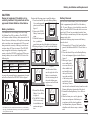
McIntosh Laboratory, Inc.
2 Chambers Street Binghamton, New York
MCLK12
Analog Clock
Owner’s Manual
13903-2699 Phone: 607-723-3512
www.mcintoshlabs.com
The lightning flash with arrowhead, within an equilateral
triangle, is intended to alert the user to the presence of
uninsulated “dangerous voltage” within the product’s enclosure that may be of sufficient magnitude to constitute
a risk of electric shock to persons.
WARNING - TO REDUCE RISK
OF FIRE OR ELECTRICAL
SHOCK, DO NOT EXPOSE
THIS EQUIPMENT TO RAIN OR
MOISTURE.
IMPORTANT SAFETY
INSTRUCTIONS!
PLEASE READ THEM BEFORE
OPERATING THIS EQUIPMENT.
1. Read these instructions.
2. Keep these instructions.
3. Heed all warnings.
4. Follow all instructions.
5. Do not use this apparatus near water.
6. Clean only with a dry cloth.
7. Do not block any ventilation openings. Install
in accordance with the manufacturer’s instructions.
8. Do not install near any heat sources such as
radiators, heat registers, stoves, or other apparatus (including amplifiers) that produce heat.
9. Do not defeat the safety purpose of the polarized or grounding-type plug. A polarized plug
has two blades with one wider than the other.
A grounding type plug has two blades and a
2
The exclamation point within an equilateral triangle is
intended to alert the user to the presence of important
operating and maintenance (servicing) instructions in the
literature accompanying the appliance.
NO USER-SERVICEABLE PARTS
INSIDE. REFER SERVICING TO
QUALIFIED PERSONNEL.
third grounding prong. The wide blade or the
third prong are provided for your safety. If
the provided plug does not fit into your outlet,
consult an electrician for replacement of the
obsolete outlet.
10. Protect the power cord from being walked on
or pinched particularly at plugs, convenience
receptacles, and the point where they exit
from the apparatus.
11. Only use attachments/accessories specified by
the manufacturer.
12. Use only with the cart, stand, tripod, bracket,
or table specified by the manufacturer, or sold with the apparatus. When a cart is used, use
caution when moving the cart/
apparatus combination to avoid
injury from tip-over.
13. Unplug this apparatus during lightning storms
or when unused for long periods of time.
14. Refer all servicing to qualified service personnel. Servicing is required when the apparatus
has been damaged in any way, such as power-
To prevent the risk of electric
shock, do not remove cover or
back. No user-serviceable parts
inside.
supply cord or plug is damaged, liquid has
been spilled or objects have fallen into the
apparatus, the apparatus has been exposed to
rain or moisture, does not operate normally, or
has been dropped.
15. Do not expose this equipment to dripping or
splashing and ensure that no objects filled
with liquids, such as vases, are placed on the
equipment.
16. To completely disconnect this equipment from
the a.c. mains, disconnect the power supply
cord plug from the a.c. receptacle.
17. The mains plug of the power supply cord shall
remain readily operable.
18. Do not expose batteries to excessive heat such
as sunshine, fire or the like.
19. Connect mains power supply cord only to a
mains socket outlet with a protective earthing
connection.
Battery Installation and Replacement
CAUTION:
Danger of explosion if the battery is incorrectly installed. Only install one of the
approved Lithium Batteries listed below.
Battery Installation
The McIntosh MCLK12 Analog Clock uses a long
life Lithium Coin Cell type battery. The MCLK12
will function without a battery when connected to AC
Power. However, the battery will keep the current time
in the event there is an interruption of AC Power and
thus prevents the necessity of having to reset the correct time when AC Power is restored. The MCLK12
may be supplied with a battery depending on the
country where the MCLK12 is purchased. When purchasing a battery for use in the MCLK12 refer to the
following list:
Perform the following steps to install the battery:
1. Press the tab and lift up on the Backup Battery
Cover and temporarily
place it aside. Refer to
figure 2.
BACKUP
2. Remove the CR2032
BATTERY
Battery from its packaging.
3. Orient the battery so
Figure 2
the + symbol (engraved into one side of the battery) is facing up.
4. Refering to figures 3, 4 and 5 insert the battery
Battery
Socket
Tabs
CR2032
3V
Approved Lithium Batteries
Brand
IEC No.
ANSI/NEDA No.
Energizer
1
CR2032
5004LC1
Panasonic
CR2032(PA/1B)1
5004LC1
Access to the recessed battery compartment is located
on the Rear Panel of the MCLK12. Refer to figure 1.
Figure 3
Figure 4
CR2032
3V
into the socket. Make
sure the right side of the
battery is seated under
the two retaining tabs of
the socket before pressing down on the left side
of the battery.
Figure 5
Battery
Compartment
BACKUP
BATTERY
Figure 1
CR Lithium Coin Cells contain Perchlorate Material - special handling
may apply. For additional information go to www.dtsc.ca.gov/hazaedous
waste/perchlorate/index.cfm
1
5. Reinstall the Backup
Battery Cover. Refer
to figure 6.
6. The MCLK12 Analog
Clock is now ready
for installation, connection and operation.
BACKUP
BATTERY
Figure 6
Battery Removal
The life of the Lithium Battery used in the McIntosh
Clock is approximately the shelf life of the battery
(10 - 15 years). However, it is advisable to remove the
battery from the MCLK12 when the clock is not connected to AC Power for an extended period of time.
This will help to extend battery life and avoid possible
damage to the clock.
Perform the following steps to remove the battery
from the clock:
1. Disconnect the AC Power Cord from the Rear
panel of the McIntosh MCLK12 Clock. Refer to
figure 1.
2. Press the tab and lift up on the Backup Battery
Cover and temporarily place it aside. Refer to
figure 2.
3. Refering to figure 7,
use a small pocket
size screw driver (or
other suitable tool)
and carefully insert
the tip of the tool between the metal tab
of the battery socket
and the left side of
Figure 7
the battery. Then rotate the tool to release the battery from the socket.
Remove the battery from inside of the clock.
5. Reinstall the Backup Battery Cover. Refer to
figure 6.
6. Store the battery in a cool dry place for
future use or dispose of the battery in
accordance with the local regulations
for lithium battery disposal. Batteries
should never be thrown away or incinerated.
CR2032
3V
3
Thank You
Your decision to own this McIntosh MCLK12 Analog
Clock ranks you at the very top. You now have “The
Best.” The McIntosh dedication to “Quality,” is assurance that you will receive many years of acurate time
keeping from this unit.
Please take a short time to read the information in
this manual. We want you to be as familiar as possible with all the features and functions of your new
McIntosh.
Please Take A Moment
The serial number, purchase date and McIntosh Dealer
name are important to you for possible insurance
claim or future service. The spaces below have been
provided for you to record that information:
Serial Number:________________________________
Purchase Date:_ _______________________________
Dealer Name:_ ________________________________
Technical Assistance
If at any time you have questions about your McIntosh
product, contact your McIntosh Dealer who is familiar
with your McIntosh equipment and any other brands
that may be part of your system. If you or your Dealer
wish additional help concerning a suspected problem,
you can receive technical assistance for all McIntosh
products at:
McIntosh Laboratory, Inc.
2 Chambers Street
Binghamton, New York 13903
Phone: 607-723-3512
Fax: 607-724-0549
4
Customer Service
If it is determined that your McIntosh product is in
need of repair, you can return it to your Dealer. You
can also return it to the McIntosh Laboratory Service
Department. For assistance on factory repair return
procedure, contact the McIntosh Service Department
at:
McIntosh Laboratory, Inc.
2 Chambers Street
Binghamton, New York 13903
Phone: 607-723-3515
Fax: 607-723-1917
Table of Contents
Safety Instructions....................................................... 2
Battery Installation and Replacement.......................... 3
Thank You and Please Take a Moment........................ 4
Technical Assistance and Customer Service............... 4
Table of Contents......................................................... 4
General Information.................................................... 4
Connector and Cable Information............................... 5
Introduction.................................................................. 5
Performance Features.................................................. 5
Dimensions.................................................................. 6
Installation................................................................... 7
Rear Panel Connections............................................... 8
Connections................................................................. 9
Front Panel Displays and Controls............................. 10
How to Operate the Clock..........................................11
Photos.................................................................... 12-13
Specifications............................................................. 14
Packing Instructions.................................................. 15
General Information
1. For additional connection information, refer to the
owner’s manual(s) for any component(s) connected
to the MCLK12 Analog Clock.
2. The Main AC Power going to the MCLK12 and
any other McIntosh Component(s) should not be applied until all the system components are connected
together. Failure to do so could result in malfunctioning of some or all of the system’s normal
operations. When other McIntosh Components are
in their Standby Power Off Mode, the Microprocessor’s Circuitry inside each component is active and
communication is occurring between them.
3. When discarding the unit, comply with
local rules or regulations. Batteries should
never be thrown away or incinerated but
disposed of in accordance with the local
regulations concerning battery disposal.
4. For additional information on the
MCLK12 and other McIntosh Products
please visit the McIntosh Web Site at
www.mcintoshlabs.com.
Copyright 2011 © by McIntosh Laboratory, Inc.
General Information, Connector/Cable Information, Introduction and Performance Features
Connector/Cable Information
Power Control Connector
The MCLK12 Power Control Input receives an On/
Off signal from +5 to +12 volts. The Power Control
Output will in turn provide a +5 to +12 volts Output
Signal with a total current up to
Power
50mA. An additional connecControl
tion is for controlling the illuMeter
Illumination
mination of Hours and Minutes
Control
Pass Thru
Meters on the MCLK12 along
Ground
with Power Output Meters on
compatible McIntosh Power Amplifiers. The 1/8 inch
stereo mini phone plug connects to a McIntosh Preamplifier or A/V Control Center Power Control Output.
Note: The Power Control Connecting Cable is available
from the McIntosh Parts Department:
Data and Power Control Cable Part No. 170-202
Six foot, shielded 2 conductor, with 1/8 inch stereo
mini phone plugs on each end.
Introduction
The McIntosh MCLK12 Analog Clock is a precision
time piece designed to complement any Audio or Audio/Video System.
Performance Features
• Illuminated Meters
The large Minutes and Hour Meters on the MCLK12
display the current time and are illuminated with extra
long life Light Emitting Diodes (LEDs)
• Precision Oscillator
The MCLK12 circuitry utilizes a precision temperature compensated quartz crystal oscillator for accurate
time keeping, even with room temperature fluctuations.
• Lithium Battery
The long life Lithium Battery is used for backup of
the crystal oscillator for accurate time keeping in the
event there is an interuption of AC Power.
• Precision Parts
Only the finest precision parts are used throughout.
• Efficient Power Supply
Fully regulated Power Supply ensures stable, accurate time keeping operation even though the power
line many vary. Its efficient design allow for very low
energy consumption.
• Fiber Optic Solid State Front Panel Illumination
The even Illumination of the Front Panel is accomplished by the combination of custom designed Fiber
Optic Light Diffusers and extra long life Light Emitting Diodes (LEDs).
• Glass Front Panel
The famous McIntosh Illuminated Glass Front Panel
ensures the pristine beauty of the MCLK12 will be
retained for many years.
• Power Control
The Power Control Input and Output connections
provides convenient Turn-On/Off of Front Panel Illumination of the MCLK12 along with other McIntosh
Components.
5
Dimensions
The following dimensions can assist in determining
the best location for your MCLK12.
Front View of the MCLK12
17-1/2"
44.45cm
8-7/8"
22.54cm
Side View of the MCLK12
4-3/16"
10.63cm
Rear View of the MCLK12
16-15/16"
43.02cm
3-5/32"
8.02cm
3-15/16"
10.00cm
BACKUP
BATTERY
7-5/32"
18.18cm
7-5/32"
18.18cm
2-5/8"
6.67cm
6
Dimensions and Installation
Installation
Wall Mounting
The MCLK12 is supplied with two Wall Anchors for
mounting the clock on a wall. The Wall Anchors will
accommodate wall thickness ranging from 1/8 inch
(0.318 cm) to 5/8 inch (1.59 cm) thick (typical residential drywall construction). Refer to figure 2. Additional wall fasteners may be needed when the wall
thickness is greater then 5/8 of an inch or with other
types of wall construction. It is recommended that the
Professionals at your McIntosh Dealer, who are skilled
in all aspects of installation and operation, install the
MCLK12 Analog Clock and any associated audio/
video equipment.
1. Use the supplied MCLK12 Mounting Template
sheet (drawn actual size) to determine the clock’s
location on the wall. Refer to figure 1.
2. Temporarily tape the Mounting Template to the
wall in the desired location.
3. Before performing step 4, make certain there is
no plumbing, electrical wires, electronic cables or
any heating/cooling duct
work located in the wall Dry
behind where the clock Wall
will be mounted.
4. Using a drill equipped
Drill
with a 3/8 inch (9.5 mm)
Bit
drill bit, drill two holes
Figure 3
MCLK12 Front and Rear Panels shown actual size
8-3/4”
Distance between mounting hole centers, 12” (30.48cm)
22.23cm
2-13/16”
1-3/4”
1-3/4”
7.14cm
4.45cm
2-1/16”
6.51cm
+
Rear Panel
Mounting
Opening
4.45cm
2-9/16”
5.24cm
+
Rear Panel
Mounting
Opening
Center Line
Center Line
The MCLK12 Analog Clock is designed to be placed
upright on a table or shelf, standing on its feet. It may
also be wall mounted.
The clock produces very little heat of its own.
However, it is advisable not to install the MCLK12
directly above a heat generating device. Cool operation ensures the longest possible operating life for any
electronic instrument.
Figure 1
into the drywall as indicated on the Mounting
Template. Refer to figures 1 and 3.
5. Remove the Mounting Template from the wall.
6. Locate the two supplied Wall Anchors and insert
them into the just drilled openings in the wall.
Refer to figures 2 and 4.
7. Using a suitable tool,
lightly tap the Wall
Figure 2
Anchors until the antirotation tabs are into the drywall.
8. Using a suitable tool,
Dry
Anti-Rotate
rotate the screw head
Wall
Tabs
clockwise of the Wall
Anchors until it starts to
tighten up. It will take
Wall
many turns. Refer to
Anchor
Figure 4
figures 5, 6 and 7.
Figure 5
Figure 6
9. Now rotate the screw of
the Wall Anchor counterclockwise about 6 and
one half turns.
10. Try placing the MCLK12
on the wall by lining up
the rear panel openings of
Figure 7
the clock with the screw
heads of the Wall Anchors. If necessary adjust the
Wall Anchor screws.
11. Proceed to the MCLK12 Rear Panel Connections
on page 8.
7
Rear Panel Connections
Opening used for
wall mounting of
the MCLK12
Connect the MCLK12 power
cord to a live AC outlet.
Refer to information on the
back panel of your MCLK12
to determine the correct voltage for your unit
Opening used for
wall mounting of
the MCLK12
BACKUP
BATTERY
POWER CONTROL INput receives
a turn-on signal from a Preamplifier
or A/V Control Center
8
Removable cover provides access
for battery installation and removal.
For addititonal information refer to
page 3.
POWER CONTROL OUTput sends
a turn-on signal to a component
when the MCLK12 receives a turnon signal
Connections
Connections
Preamplifier
When the MCLK12 Power Control Input is connected
to a McIntosh Preamplifier or A/V Control Center
with Power Control Functions, the Clock’s Front Panel
Nomenclature and/or Meter Illumination can be remotely switched On/Off.
The connection instructions below, together with
the Connection Diagram are an example of a typical audio system. Your system may vary from this,
however the actual components would be connected in
a similar manner. For additional information refer to
“Connector and Cable Information” on page 5.
Power Control Connections:
1. Connect a Control Cable from the Preamplifier or
A/V Control Center Power Control Output 1 Jack
to the MCLK12 POWER CONTROL MAIN Jack.
2. Connect a Control Cable from the MCLK12
POWER CONTROL Out Jack to the Power Amplifier Power Control In Jack.
AC Power Cords Connections:
3. Connect the MCLK12 to a live AC outlet as illustrated.
Connect to
AC Outlet
BACKUP
BATTERY
Power Amplifier
6.6
9
Front Panel Displays and Controls
Meter indicates the
current Hour
TIME ADJUST Control allows setting
the current time in Hours and Minutes
10
Meter indicates the
current Minute
METER LIGHTS switches On/Off
illumination of the Meters (Hours
and Minutes) also switches On/
Off illumination of the Front Panel
nomenclature
How to Operate the Clock
How to Operate the Clock
Setting the Time
The internal time keeping circuitry of MCLK12 is
always active when the clock is connected to a live
AC Outlet. The correct time needs to be manually set
when the clock is conected for the first time. To set the
current time perform the following:
1. Press and hold in the TIME ADJUST Control
until only the Meter indicating
HOURS is illuminated. Refer to
figures 10 and 11.
2. Rotate the TIME ADJUST Control
clockwise or counterclockwise to
set the current Hour on the Meter.
3. Press in the TIME ADJUST
Figure 10
Control once and the Meter indicating MINUTES will now be illuminated. Refer to
figures 10 and 12.
4. Rotate
the TIME
ADJUST
Control
clockwise
or counterclockwise
Figure 11
to set the
current
Minute on
the Meter.
5. Press in
the TIME
ADJUST
Figure 12
Control
once and both Meters will now be illuminated
displaying the current time.
Front Panel Illumination
When the MCLK12 is connected to a McIntosh Preamplifier, A/V Control Center, Integrated Amplifier
or A/V Receiver via the Power Control Connection,
the Front Panel Illumination of the clock will go On/
Off with the McIntosh Component.
The clock will continue to display the current time
even when the Front Panel Illumination is Off. If the
McIntosh Component offers remote control of meter
illumination via the Power Control Connection the illumination of the Meters on the clock will also go On/
Off.
The MCLK12 Front Panel METER LIGHTS
Control also allows control of Meter and Front Panel
Nomenclature Illumination. To select Meter and Nomenclature Illumination perform the following steps:
1. Rotate the METERS LIGHTS
Control to switch the Meter illumination On/Off. Refer to figures 11,
12 and 13.
2. Press the METERS LIGHTS Control to switch On/Off illumination
of the Meter and Nomenclature.
Figure 13
11
12
Photos
13
Specifications
Specifications
Time Base
Temperature compensated quartz crystal oscillator
Time Base Accuracy
±2 parts per million from 0°C to +40°C
Clock Time Display
Dynamic magnetic meters
Backup Battery Type
Approved Lithium Batteries
Brand
IEC No.
ANSI/NEDA No.
Energizer
CR20321
5004LC1
Panasonic
CR2032(PA/1B)1
5004LC1
Power Control Input and Output
5-15VDC, 50mA maximum
Power Requirements
100V ~ 50/60Hz at 2.0 Watts
110V ~ 50/60Hz at 2.0 Watts
120V ~ 50/60Hz at 2.0 Watts
220V ~ 50/60Hz at 2.0 Watts
230V ~ 50/60Hz at 2.0 Watts
240V ~ 50/60Hz at 2.0 Watts
Note: Refer to the rear panel of the MCLK12 for the correct voltage.
14
System Overall Dimensions
Width is 17-1/2 inches (44.45cm)
Height is 8-7/8 inches (22.54cm)
Depth is 5 inches (52.54 cm) with AC Cord connected
System Weight
8 pounds (3.62 Kg) net, 10 pounds (4.54 Kg) in shipping carton
System Shipping Carton Dimensions
Width is 22-3/4 inches (57.8cm)
Depth is 13-1/4 inches (33.7cm)
Height is 7-1/2 inches (19.1cm)
Packing Instructions
Packing Instructions
In the event it is necessary to repack the equipment for
shipment, the equipment must be packed exactly as
shown below. Failure to do this will result in shipping
damage.
Use the original shipping carton and interior parts
only if they are all in good serviceable condition. If
a shipping carton or any of the interior part(s) are
needed, please call or write Customer Service Department of McIntosh Laboratory. Refer to page 4. Please
see the Part List for the correct part numbers.
Quantity Part Number Description
1
034496
Shipping Carton Complete
15
McIntosh Laboratory, Inc.
2 Chambers Street
Binghamton, NY 13903
www.mcintoshlabs.com
The continuous improvement of its products is the
policy of McIntosh Laboratory Incorporated who
reserve the right to improve design without notice.
Printed in the U.S.A.
McIntosh Part No. 04118800