1
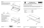
Step 15
Attach the Base Tubes to each Leg by inserting a fit
Bolt through a Tube Washer, then insert the fit Bolt
through the Base Tube and carefully thread into
each Vertical Leg.
R
Console Unit
Begin by placing the Base Tube Assembly (Locking Casters
as shown) onto the Vertical Legs.
Assembly Instructions
Hello! Thank you for choosing Anthro.
Locking Casters
Tighten all fit Bolts and Cap Screws.
Before beginning assembly of your Console Unit, take a moment to review the parts listed on the next page
to verify that your shipment is complete. Please review the assembly instructions of all Anthro products you
purchased and are planning to include in this installation, prior to beginning this assembly.
fit Tube Washer
Your Console Unit is heavy! A second person will be needed for this assembly procedure.
To make the assembly of your Console Unit even easier, we have included all of the required tools. The handy
Hex Driver Bit can be used in your electric drill in place of the Hex Driver.
Hex Driver 5/32”............................................................ 375-5000-00
Hex Driver Bit 5/32” ..................................................... 375-5003-00
Hex Key 5/32” ................................................................. 375-5016-00
Hex Key 1/4” .................................................................. 375-5024-00
3-Way Wrench ............................................................. 225-5196-03
8 oz. Rubber Mallet ..................................................... 375-5022-00
Rotate Knob to
adjust Caddy
angle.
(5/16-18 X 3.5”) fit Bolt
325-5194-00
Step 16 (uses the
fit Tube Washer
225-2050-00 or 225-3522-00
/8” Hex Key)
1
Carefully rotate your Console Unit onto the Casters.
Pop the six Small End Caps into the Leg ends.
Small End Caps
Congratulations! Your assembly is complete.
Squeeze Paddle
to adjust Caddy
height.
Adjusting your Console Caddy
Questions?
1-800-325-3841
Adjust the Caddy Shelf height by:
Adjust the Caddy Shelf angle by:
1. Squeezing and holding the Paddle.
2. Reposition the Caddy to the desired location.
3. Release the Paddle.
1. Rotating the Knob counterclockwise.
2. Reposition the Caddy to the desired angle.
3. Rotate the Knob clockwise.
Anthro Corporation Technology Furniture®
1-800-325-3841
10450 SW Manhasset Drive Tualatin, Oregon 97062
SAVE THESE INSTRUCTIONS!
anthro.com
Rev. F January 2006
Component list for part # FCCzz/xx3
Step 12 (uses the
Leave these two holes
open on the 15” Base Tube
/4” Hex Key)
1
Position the 15.27” Base Tube against the Console
Junction, then mate the Keyed Feature to the Keyed Tube
End. Secure the Base Tube using a Cap Screw & the 1/4”
Hex Key.
15.27” Base Tube
Keyed ends
Place the 15 “ Base Tube against the Base Junction and
secure using a Cap Screw.
Keyed Feature
NOTE: Do not yet fully tighten the 15” Base Tube Cap Screw.
29
Base Tube Assembly
(from Step 11)
25
22
(5/16-18 X 1.5”) Cap Screw
325-5225-00
06
Step 13 (uses the
21
08
09
Console Screw
Base
Junction-Y
/4” Hex Key)
1
Place the Console Base Junction-X onto the open ends
of the 15” & 15.27” Base Tubes as shown, then mate the
Keyed Feature to the 15.27” Keyed Tube End.
Secure both Base Tubes to the Console Base Junction
using two Cap Screws & the 1/4” Hex Key.
13
NOTE: Do not yet fully tighten the 15” Base Tube Cap Screw.
19
Leave these two holes open
15.27” Base Tube
Keyed end
15
Cap
Screw
Detailed views of all Hardware is provided with each Assembly Step.
01– fit Console Large Shelf ............. Qty. 1 ...................100-6498-00
02– fit Console Caddy ......................Qty. 1 ...................100-6499-00
03– fit Adjusta Mechanism ...............Qty. 1 ...................225-5547-00
(The Adjusta Mechanism is packaged separately & requires assembly)
04– fit Console Back Trough-X ....Qty. 1 ...................225-2367-00
05– Small Support Y ...........................Qty. 1 ...................225-2015-00
06– fit 24.875” Vertical Legs ............Qty. 6 ...................125-5230-00
07– fit 21” Base Tubes .......................Qty. 2 ...................125-5275-00
08– fit 30.5” Console Cross Tubes...Qty. 4 ...................125-5248-00
09– fit Console Base Junction-Y ...Qty. 1 ...................225-5787-00
10– Acorn Nuts ....................................Qty. 2 ...................325-5023-00
11– Cap Screws ....................................Qty. 8 ...................325-5225-00
12– fit 15.27” Keyed Base Tube .....Qty. 1 ...................125-5249-00
13– fit 15” Base Tube .........................Qty. 1 ...................125-5250-00
14– fit Console Base Junction-X ...Qty. 1 ...................225-5786-00
15– 3” Locking Casters......................Qty. 2 ...................150-5053-00
16– 5/16-18 fit Bolts ..............................Qty. 10 ................325-5194-00
17– fit Tube Washers .........................Qty. 10225-2050-00 or 225-3522-00
18–
19–
20–
21–
22–
23–
24–
25–
26–
27–
28–
29–
3” Non-Locking Casters...........Qty. 4 ...................150-5052-00
Caster Inserts ...............................Qty. 6 ...................525-5032-00
2.0” Large End Caps ...................Qty. 4 ...................175-5157-00
Insert Screws ............................. Qty. 6 ...................325-5052-00
fit Console Back Trough-Y ......Qty. 1 ...................225-2368-00
Button Head Screws ..................Qty. 4 ...................325-5003-00
1.5” Small Caps.............................Qty. 6 ...................175-5156-00
Small Support X ..........................Qty. 1 ...................225-2014-00
3
/4” Wood Screws ........................Qty. 42 ................325-5106-00
Support Screws ............................Qty. 12 ................325-5010-00
fit Corner Connector Support-X . Qty. 1 ...................225-5582-00
fit Corner Connector Support-Y . Qty. 1 ...................225-5583-00
(5/16-18 X 1.5”) Cap Screw
325-5225-00
Step 14 (uses the
Console Base Junction-X
/4” Hex Key)
1
Locking Caster
Place the non-coped ends of the two remaining Cross
Tubes against the Base Junction and loosely secure using
two Cap Screws.
Orient the remaining Base Tube assembly as shown.
Secure to the coped Cross Tube Ends by inserting
a fit Bolt through a Tube Washer, then insert the Bolt
through the Base Tube and carefully thread into each
Cross Tube, but don’t fully tighten the fit Bolts yet.
Tighten the two Cap Screws installed during
this Step.
Side
holes
Cap Screw
(5/16-18 X 3.5”) fit Bolt
fit Tube Washer
(5/16-18 X 1.5”) Cap Screw
325-5194-00
225-2050-00 or 225-3522-00
325-5225-00
1-800-325-3841
fit Tube Washer
Cross Tubes
All Fastener quantities listed here are the minimum needed
for your Console Unit assembly. There may be a few extra
Fasteners included, which are not counted in the Parts List.
Anthro Corporation Technology Furniture® 10450 SW Manhasset Drive Tualatin, Oregon 97062
Remaining Base
Tube Assembly (from
Step 9)
anthro.com
Console
Base Junction-X
FCCzz/xx3
Step 9
Step 1a
Leave these four
holes open
Insert two End Caps into the ends of both 21” Base Tubes.
Your Adjusta Mechanism comes unassembled and is
boxed separately inside the Console Unit package.
Insert Screw
Install two Caster Inserts into each Base Tube and
secure with one Insert Screw per Insert.
Brake/Paddle Assembly
Post
Begin to assemble the Mechanism by first locating the Adjusta
Crossbar and Brake/Paddle Assembly, position it as shown at
right. Depress the Paddle once to free the Brake Shaft.
Insert one Locking and one Non-Locking Caster into
each Insert of a Base Tube as shown.
Non-Locking
Caster
NOTE:: included with Adjusta Mechanism is a small bag of
Hardware containing the (1) Post, (1) Cotter Pin, (2) Hex Nuts,
(2) Wood Screws, & (2) Cable Mounts.
Locking
Caster
Step 10
15” Base Tube
Straight Ends
Install one Caster Insert into both the 15.27” & 15” Base
Tubes and secure each Insert with one Insert Screw.
Center Crossbar Flanges
Step 1b
Leave these two
holes open
Install the Cotter Pin through the single opening of the
Post to secure into place.
15.27” Base Tube
Keyed Ends
Insert one Non-Locking Caster into each Insert of both
Base Tubes as shown.
Crossbar
Place the Brake Shaft between the two center Crossbar
Flanges. Insert the Post through both center Crossbar
Flanges and Brake Shaft.
Caster Inserts placed
into the large holes
Insert Screw
(with pink threads)
325-5052-00
Brake Shaft
Insert Screw
Cotter Pin
Post
(included with 225-5547-00)
Caster Insert placed
into the large holes
Step 2 (uses the 3-Way Wrench)
Insert Screw
(with pink threads)
325-5052-00
Step 11 (uses the
/4” Hex Key)
1
Place one Base Tube Assembly (Locking Casters oriented
as shown) against the Coped Ends of two Cross Tubes.
Attach the Base Tube to the Cross Tubes by inserting
a fit Bolt through a Tube Washer, then insert the Bolt
through the Base Tube and carefully thread into each
Cross Tube, but don’t fully tighten the fit Bolts yet.
Place the Base Junction-Y against the opposite Cross
Tube Ends.
NOTE: Make certain the Keyed feature is oriented as shown.
Paddle
Repeat for remaining Crossbar end and Arm Mechanism.
Side holes
Base Tube
Assembly (from
Step 9)
Arm Mechanism
Place one Crossbar end onto the lower Crossbar
Button and Threaded Bolt (located on each of the Arm
Mechanisms). Secure the Crossbar to the Arm Mechanism
using one 5/16” Hex Nut onto the Threaded Bolt.
Locking Caster
fit Tube Washer
Brake/Paddle
Assembly
Unpack the remaining Adjusta Mechanism components
and arrange them as shown at right.
Non-Locking
Caster
fit Bolt
Cotter Pin
(included with 225-5547-00)
Cross Tube
Coped End
Cap
Screw
Cross Tube
Secure the Base Junction-Y to the Cross Tubes using
two Cap Screws and the 1/4” Hex Key.
Threaded Bolts
Keyed
Feature
NOTE:: it is very important that you attach the Crossbar
ONLY to the Lower Crossbar Button.
/16” Hex
Nut
Console Base
Junction-Y
5
DETAIL VIEW
5
/16” Hex Nut
(included with 225-5547-00)
(5/16-18 X 3.5”) fit Bolt
fit Tube Washer
(5/16-18 X 1.5”) Cap Screw
325-5194-00
225-2050-00 or 225-3522-00
325-5225-00
Anthro Corporation Technology Furniture® 10450 SW Manhasset Drive Tualatin, Oregon 97062
Lower Crossbar
Button
Crossbar
1-800-325-3841
anthro.com
FCCzz/xx3
Step 3
Step 6
Small Support
Bracket Y
Place your Console Large Shelf onto the floor with the
predrilled holes facing up.
Position both Small Support Brackets onto the Large
Shelf and align two of the holes on each Support with the
predrilled holes on the Shelf. Loosely secure each Small
Support to the Shelf using two Wood Screws per Support.
Bottom (coped) end
Determine the best height for your Console Large
Shelf. These instructions will place your Shelf 31” from
the floor using the standard 3” Casters.
Predrilled Holes
REAR Leg
Attach both center Vertical Legs by loosely installing
two Support Screws through each Connector Support
into Holes 1 & 3 from the top (non-coped end).
(non-coped)
FRONT Leg
Loosely install two Support Screws through each Small
Support into holes 1 & 3 from the top of both front Legs.
Small Support
Bracket X
CENTER Leg
Connector
Supports
Install two Support Screws through holes 1 & 3 from
the top of both rear Legs.
Hole 1
Hole 3
Support Screw
Wood Screw
3
/4” Wood Screw
325-5106-00
NOTE: For a final Large Shelf height that is lower than 31”,
adjust one hole down for each inch of variance desired.
Support Screw
325-5010-00
Step 4
NOTE: Make sure the Back Supports
are in front of the Support Brackets.
SECOND:
Install
the Wood
Screws
Place both Back Troughs onto the Console Large Shelf,
between the installed Support Brackets.
Align the two Threaded holes on each Back Trough with
those on the installed Support Brackets. Carefully, thread
one Button Head Screw through the Support Bracket, into
the Back Trough. Repeat for remaining three Button Head
Screws & Threaded Holes.
Insert two Wood Screws through the two remaining
Holes on each of the Back Trough flanges (which should
be aligned with two predrilled holes on the Shelf) and tighten
into place.
Step 7 (requires Shelf to be 12” from floor)
Back
Trough-Y
Place the Mechanism onto the Shelf Assembly.
Wood Screw
Align the Mechanism Flanges with the predrilled Holes
on the Shelf underside.
Secure the Mechanism to the Shelf using a total of twelve
Wood Screws.
FIRST Install the ButFIRST:
ton Head Screws
Back Trough
Flange
(12” high surface shown shaded)
Brake
Align the six Holes of the Brake Assembly with those on
the Shelf.
Back
Trough-X
NOTE: It may be necessary to depress the Paddle while
manipulating the Brake over the predrilled Shelf Holes.
Secure the Brake Assembly using a total of six Wood Screws.
Threaded
holes
/4” Wood Screw
325-5106-00
3
(1/4-20 X .50”) Button Head Screw
325-5003-00
Step 5
Small
Support
Bracket X
Paddle
Support Screw
325-5106-00
Connector
Support-Y
Connector
Support-X
Place each of the Connector Supports onto the top as
shown.
Wood Screw
Mechanism Flanges
Step 8 (requires Shelf to be 12” from floor)
(12” high surface shown shaded)
Rotate the Console Caddy so the predrilled holes face up.
Slide the Caddy under the Mechanism and align the three
holes located on each end of the Caddy and Mechanism.
Align the two holes on each Support with the predrilled
holes on the Shelf, then secure each Support using two
Wood Screws.
Secure the Caddy using a total of six Wood Screws. Then,
secure the Paddle to the Caddy using four Wood Screws.
Cable
NOTE: Make certain the Cable for the Paddle is positioned
underneath the Adjusta Bar.
Adjusta Bar
Wood Screw
3
/4” Wood Screw
325-5106-00
Anthro Corporation Technology Furniture® 10450 SW Manhasset Drive Tualatin, Oregon 97062
3
1-800-325-3841
/4” Wood Screw
325-5106-00
Paddle
anthro.com
Hole 1