1
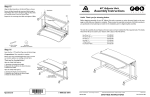
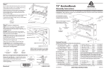
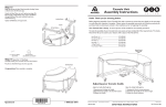
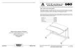
Threaded holes
Step 7a
Install Non-skid Pads on the top of the Trolley Trunk
Covers to cushion the edge of each Trunk Assembly where it
meets the cover. Install pads on the inside face of the cover,
at the edge, about 3.5” below the threaded holes at the top of
the cover.
3.5”
Assembly Instructions
Non-Skid Pads
Button Head Screws
Non-Skid Pad
175-5068-03
Trolley Cart
TECHNOLOGY FURNITURE®
Hello!
Thank you for choosing Anthro.
Trunk Cover
Step 7b
All fastener quantities shown are the
minimum needed for this assembly.
There may be a few extras provided
which are not required.
STOP: If you purchased a Trolley
Equipment Shelf, Additional wood shelf, or Trolley
tray read those instructions before installing the
trunk covers.
15
12
16
11
17
Install the Trolley Trunk Covers by orienting both Covers with
the Trunk Assemblies.
18
Button Head
Screws
10
09
The following Tools (not shown at right) have
been provided:
Hex Driver 5/32”.............375-5000-00
Secure the top and bottom of each Cover using a total of four
Button Head Screws per Cover.
13
14
Before beginning assembly of your
Trolley, please take a moment to review the parts listed below to verify
that your shipment is complete.
Hex Key 6mm................375-5013-00
/16” Allen Key................375-5028-00
3-way Wrench.............225-5196-03
5/32” Driver Bit............375-5003-00
08
01
3
07
02
04
05
(1/4-20 X .375”) Button Head Screw
325-5210-00
Component list for
part # TR18zz/xx and TT18zz/xx.
Step 8
Finally, place the main Trolley Shelf onto the installed
Shelf & Handle Sides, aligning the six holes on the
Shelf with those on the Sides.
Secure the Shelf to the Sides using a total of six
/4” Wood Screws. Tighten all Screws and Nuts.
3
3
/4” Wood Screws
into the six Trolley
Shelf holes
Congratulations! Your assembly is complete!
/4” Wood Screw
325-5106-00
3
Questions?
03
01–Trolley Trunk Assembly (X) ...........Qty. 1..................................................
TR18zz/xx.............................................................................. 835-5018-00
TT18zz/xx............................................................................... 835-5401-00
02– 5” Total Lock Casters.................. Qty. 2 ..................... 150-5081-00
03– 5/16-18 Button Head Screw........ Qty. 16................... 325-5188-00
04– 5/16-18 X 1” Tube Screws............ Qty. 4 ..................... 325-5136-00
05– 5” Swivel Lock Casters............... Qty. 2 ..................... 150-5080-00
06– Trolley Trunk Covers.........................Qty. 2 .................................................
TR18zz/xx.............................................................................. 225-5753-00
TT18zz/xx............................................................................... 225-4278-00
07– 18.25” Lower Cross Tube................Qty. 1.......................125-5244-xx
08– Trolley Trunk Assembly (Y) ...........Qty. 1..................................................
TR18zz/xx.............................................................................. 835-5019-00
TT18zz/xx............................................................................... 835-5402-00
STOP: If you purchased a swing out mouse shelf read
those instructions before installing the top.
1-800-325-3841
06
09– 12” Upper Cross Tube................ Qty. 1...................... 125-5243-00
10– Trolley Cable Wraps..........................Qty. 2...................... 225-5756-00
11– 1/4-20 Keps Nuts................................Qty. 6...................... 325-5202-00
12– 18” Handle...........................................Qty. 1...................... 125-5245-00
13– Shelf & Handle Side (X)............. Qty. 1...................... 225-5754-00
14– 18.5” Wide Trolley Shelf.................Qty. 1...................... 100-6495-00
15– Shelf & Handle Side (Y)..................Qty. 1...................... 225-5755-00
16– 3/4” Wood Screws...............................Qty. 6.......................325-5106-00
17– 1/4-20 Button Head Screws ....... Qty. 14....................325-5210-00
18– 1/4-20 X 2” Handle Screws ......... Qty. 2...................... 325-5034-00
19– Non-Skid Pads (not shown).......... Qty. 8...................... 175-5068-03
Anthro® Corporation Technology Furniture® 10450 SW Manhasset Drive Tualatin, Oregon 97062 anthro.com
1-800-325-3841
SAVE THESE INSTRUCTIONS!
November 2010, Rev H
Questions? 1-800-325-3841
Trolley Cart
Step 1
before you begin, take special notice of the features on the
Swivel Lock Casters (those with the Green Brake Pedals).
The teeth on the plate of both Swivel Lock Casters need to face
the rear of the Trunk Assemblies.
Swivel Lock Caster
(Green Brake Pedal)
NOTE: There are a matching set
of teeth on the truck. Since the
truck rotates, their orientation is
not critical.
Step 4 (requires the 6mm Hex Key)
Rotate the Cart Assembly (from Step 3) onto the Casters.
Place the 12” Upper Cross Tube between each Trunk Assembly
and align the Tube with the Large hole, midway
up the Trunk.
12” Cross Tube
Carefully secure into place using one Tube Screw per end.
Step 2 will give further instructions about securing the
Casters to the Trunk Assemblies.
Large hole
Truck
Teeth
(on the Plates) faces the rear of
the Trunk Assemblies
(5/16-18 X 1”) Tube Screw
325-5136-00
Plate
Installed to the Trunk
Assemblies
Position one Trolley Shelf & Handle Side against a Trunk Assembly. Insert the two posts of a Side into holes 3 & 5 (from
the top) of the Trunk. Loosely attach the Side to the Trunk
with one Button Head Screw and Keps Nut. Repeat for the
other Side.
Step 2 (requires the 3-Way Wrench)
STOP: If you purchased a Trolley Base Shelf, read those
instructions now.
Trunk Assembly (Y)
Install all four Casters to both Trunk Assemblies using four Button
Head Screws per Caster.
DOUBLE Check the installation of the Swivel Lock Casters
(Green Brake Pedal) by positioning the Trunk Assembly & Caster
as shown. Then depress the Brake. If it is installed correctly, the
Caster will be locked in a parallel orientation (as shown) with the
Trunk Assembly.
NOTE: Make certain to install one Swivel Lock Caster (green brake)
and one Total Lock Caster (black brake) onto each
Trunk Assembly.
Step 5 (requires the 3-Way Wrench)
Hole 3
Shelf & Handle Side
(Y)
Place the Trolley Handle between both Sides. Insert a Handle
Screw through both ends of the Side and carefully thread into
the Handle. Tighten the Button Head Screws on the Sides.
NOTE: By installing the Side posts into holes 3 & 5, your final
Shelf height will be 36” from the floor.
Rear of the Trunk Assemblies
Swivel Lock Caster
(Green Brake Pedal)
rear position
Hole 5
Shelf & Handle Side
(X)
Post
Keps Nut
Handle Screw
Button Head Screw
Total Lock Caster
(Black Brake Pedal)
front position
(1/4-20 X .375”) Button Head Screw
325-5210-00
(1/4-20) Keps Nut
325-5202-00
(1/4-20 X 2”) Handle Screw
325-5034-00
(5/16-18 X 3/4”) Button Head Screw
325-5188-00
Step 3 (requires the 6mm Hex Key)
Step 6 (requires the 3-Way Wrench)
Trunk Assembly (X)
Determine the location for your Trolley Cable Hangers, then
position one against a Trunk Assembly.
Position both Trunk Assemblies and the 18” Lower Cross Tube
as shown.
Insert the 18” Cross Tube into the Large Holes of each Trunk
and loosely attach the Tube to each Trunk using one Tube
Screw per end.
Trunk Assembly (Y)
Large hole
Trolley Handle and Shelf & Handle Side (Y)
are removed for clarity.
Insert two Button Head Screws through the Cable Hanger and
capture on the opposite side using two Keps Nuts.
Repeat for remaining Cable Hanger.
Button Head
Screw
Hole 7
Hole 9
NOTE: The 18” Cross Tube ends are keyed to fit into the Trunk
Assemblies.
Cable Hanger
NOTE: If you purchased a Trolley Base Shelf, install the Casters
to the Trunk Assemblies during this Step.
Keyed Cross Tube
ends
( /16-18 X 1”) Tube Screw
325-5136-00
5
Anthro® Corporation Technology Furniture® 10450 SW Manhasset Drive Tualatin, Oregon 97062 anthro.com
(1/4-20 X .375”) Button Head Screw
325-5210-00
(1/4-20) Keps Nut
325-5202-00
anthro.com
Shelf & Handle Side
(X)
Keps Nut