1
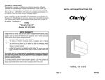
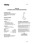
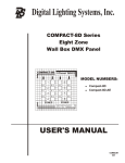
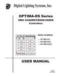
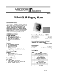
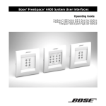
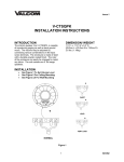
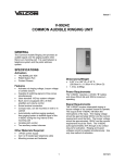
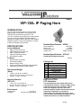
ISSUE 5 VIP-130L IP Paging Horn INTRODUCTION The VIP-130L IP Paging Horn is a self contained paging system which enables voice paging up to 1200 feet from an Ethernet connection. The VIP-130L consists of a high efficiency 5 Watt Class-D Horn and a VIP-LLE Network Extender allowing stand alone capability when used with a SIP enabled telephone system or can be accessed from a variety of Valcom managed VoIP products. Nominal Specifications – HORN SPECIFICATIONS Input Impedance: Input Level: Output Impedance: Output Level: Access Methods PBX, FXO Port w/VIP-811 POTS telephone set w/VIP-811 PBX, FXS Port w/VIP-821 Valcom M Cast Page Group SIP telephone system 600 Ohms -10dBm 600 Ohms -10dBm nominal Nominal Specifications – VIP-LLE Via 802.3af PoE Ethernet Switch: Class 3 Features RJ-45 network connection LED Status Indicator Network activity LEDs Power over Ethernet (PoE) 802.3af compatible High Efficiency Class-D 5 Watt Amplifier Packing List Qty 1 1 1 2 4 4 1 Dimensions/Weight (Horn) 7.00” H x 10.00" W x 10.00" D (18.75 cm H x 25.4 cm W x 26.4 cm D) Weight: 5.8 lbs. (2.63 kg) Network Extender (VIP-LLE) INSTALLATION FCC Information 1.30” H x 6.10" W x 6.00" D (3.51 cm H x 15.72 cm W x 13.51 cm D) Weight: 0.85 lbs. (0.39 kg) This equipment has been tested and found to comply with the limits for a Class A digital device, pursuant to Part 15 of the FCC Rules. These limits are designed to provide reasonable protection against harmful interference when the equipment is operated in a commercial environment. This equipment generates, uses and can radiate radio frequency energy and if not installed and used in accordance with the Environment Temperature: Humidity: Item VIP-LLE Network Extender 5 Watt High Efficiency Horn VSP Document Mounting Brackets Rubber Pads Wood Screws “C” Clamp 0 to +40° C 0 to 85% non-precipitating 1 947628 instruction manual, may cause harmful interference to radio communications. Operation of this equipment in a residential area may cause harmful interference in which case the user will be required to correct the interference at his own expense. Precautionary Designations CAUTION RISK OF ELECTRIC SHOCK DO NOT OPEN A “C” clamp is provided with the horn to allow mounting to a beam. Place the bolt through the hole in the bottom of the base to secure the “C” clamp to the beam. It is suggested that the horn be mounted to the underside of the “I” beam to provide maximum positioning adjustments. The base has pre-drilled holes for a doublegang square electrical box, but by drilling out additional knockout holes, the base can be mounted to a single-gang or octagon box. The horn may be rotated or moved up and down to obtain the desired position by loosening the position adjustment knob at the bottom of the unit approximately one turn. Make required adjustments and re-tighten knob. CAUTION: To reduce the risk of electric shock, Do not remove cover. No user serviceable parts inside. Refer servicing to qualified service personnel. This symbol indicates that dangerous voltage constituting a risk of electric shock is present within this unit. This symbol indicates that there are important operating and maintenance instructions in the literature accompanying this unit. Mounting (VIP-LLE) The VIP-LLE Network Extender is designed for wall or shelf mounting and must be within 300 feet of the network switch. Shelf: Provided with the VIP-LLE Network Extender are four rubber pads. Peel the pads from the carrier backing and place at the four corners of the bottom of the unit. Wall: Using the brackets and wood screws provided, secure the VIP-LLE Network Extender to the wall. Mounting (HORN) The horn should be mounted 15 to 20 feet above the floor to allow for best sound distribution. The unit can be mounted to a wall, a beam or an electrical box. NOTE: For ease of installation, the base can be attached to the speaker before or after the base is mounted. Loosen position adjustment knob Insert the ball of the base into the socket of the speaker Tighten the position adjustment knob Mount the base to a wall using the two pre-drilled holes provided. 2 947628 Interconnections The only method of powering the VIP-130L IP Paging Horn is via a Power over Ethernet (PoE) switch or power injector meeting the 802.3af specification. Make all required signal connections before connecting to Ethernet switch or power injector meeting the 802.3af specification. Power is supplied to the horn assembly via the VIP-LLE Network Extender. Network Connection As shown in Figure 3, the VIP-LLE Network Extender has one RJ-45 network connector on the front panel. Use a standard Ethernet patch cable to connect the NETWORK connector of the VIP-LLE Network Extender to a 802.3af compliant PoE port (300 feet maximum distance). Signal Connections As shown in Figure 3 and 4, audio output connections are made on the rear panel of the VIPLLE Network Extender. Versions of the VIP-LLE Network Extender with the color-coded, 8-pin screw connector will connect standard CAT-5 twisted-pair cable from the rear panel color coded connector of the VIP-LLE Network Extender to the supplied VM186 RJ-45 connector (900 feet maximum distance). Connect RJ-45 connector of horn to VM-186 RJ-45 socket. For versions of the VIP-LLE Network Extender with the RJ-45 Audio Output connector, the horn may be connected directly to the RJ-45 port. If additional length is required, any standard T568A or T568B extension may be used (900 feet maximum). Status Indicator Lights The VIP-LLE Network Extender has 3 status indication lights: STATUS: Flashes during normal operation, and solid when unit in reset. LINK: Indicates 100 Mbit Ethernet connection when illuminated. No activity indicates 10 Mbit connection. Act: Indicator flashes to indicate network activity Operation Provide paging from SIP connection or via a variety of Valcom managed VoIP products. Integration to customer telephone system can be via SIP registration, FXO port (with VIP-811), or FXS port (with VIP-821). Setup Information specific to your application will need to be programmed into the VIP-130L using a computer. The PC used for programming would be connected to the same subnet as the VIP-130L. Setup will be done using the IP Solutions Setup Tool. The IP Solutions Setup Tool may be downloaded from the Valcom website at www.valcom.com. TECHNICAL ASSISTANCE Assistance is available from the factory when problems are encountered. Call (540) 563-2000 and press 1 for Technical Support or visit our website at http://www.valcom.com. Valcom equipment is not field repairable. Valcom, Inc. maintains service facilities in Roanoke, VA. Should repairs be necessary, attach a tag to the unit clearly stating your company name, address, phone number, contact person and the nature of the problem. Send the unit to: Valcom, Inc. Repair & Return Dept. 5614 Hollins Road Roanoke VA. 24019 VALCOM LIMITED WARRANTY Valcom, Inc. warrants its products only to the original purchaser, for its own use, to be free from defects in materials and workmanship under conditions of normal use and service for a period of one year from the date of shipment. This Limited Warranty obligation shall be limited to the replacement, repair or refund of any such defective device within the warranty period, provided that: 1. inspection by Valcom, Inc. indicates the validity of the claim; 2. the defect is not the result of damage, misuse or negligence after the original shipment; 3. the product has not been altered in any way or repaired by others and that factory sealed units are unopened (a service charge plus parts and labor will be applied to units defaced or physically damaged); 4. freight charges for the return of products to Valcom are prepaid; 5. all units 'out of warranty' are subject to a service charge. The service charge will cover minor repairs (major repairs will be subject to additional charges for parts and labor). This Limited Warranty is in lieu of and excludes all other warranties, expressed or implied and in no event shall Valcom, Inc. be liable for any anticipated profits, consequential damages, loss of time or other losses incurred by the buyer in connection with the purchase, operation, maintenance, installation, removal or use of the product. The maximum liability of Valcom under this warranty is limited to the purchase price of the specific Product covered by the warranty. Disclaimer. Except for the Limited Warranty provided herein, the product is provided “as-is” without any warranty of any kind whatsoever including, without limitation, any WARRANTY OF MERCHANTABILITY, FITNESS FOR A PARTICULAR PURPOSE OR NON-INFRINGEMENT. This warranty specifically excludes damage incurred in shipment. In the event a product is received in damaged condition, the carrier should be notified immediately. Claims for such damage should be filed with the carrier involved in accordance with the F.O.B. point. Headquarters: Valcom, Inc. 5614 Hollins Road Roanoke, VA 24019-5056 Phone: (540) 563-2000 FAX: (540) 362-9800 3 947628 Note: The screw terminals are removable. Gently lift away from the circuit board to remove. Make the necessary wire connections, then replace the screw terminals over the pins on circuit board. Paging Horn RJ45 Front View BROWN VALCOM Status Link Act BROWN WHITE/BROWN VIP-LLE GREEN GREEN WHITE/GREEN WHITE/GREEN ORANGE 802.3af Compliant PoE Network Port WHITE/ORANGE BLUE W/BL W/O W/GN BROWN WHITE/BROWN W/BR BLUE WHITE/BLUE WHITE/BLUE BLUE VM-186 Rear View with Screw Terminal Connector Note: The Brown and White/brown pair should be twisted together and inserted into the connector noted on the drawing and the Green and White/Green pair should also be twisted together and inserted into the connector that is noted on the drawing. WHITE/ORANGE NOT USED 900' MAX DISTANCE CAT 3/5/6 Figure 3 AUDIO OUTPUT Rear View with RJ-45 Connector Figure 4 4 IP Paging Horn 947628