1
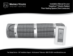
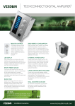
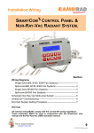
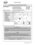
SmartCom Room Station
Installation Instructions
1057308A • February 2007
Copyright © 2007, GE Security Inc.
Introduction
This is the GE SmartCom Room Station Installation Instructions
for model CC-SCRS01. This document describes how to mount
and wire the room station.
SmartCom provides a modular, expandable system for the distribution of music and intercom functions throughout the home.
The SmartCom room station (Figure 1) provides a single, convenient graphical LCD keypad to control the SmartCom audio and
intercom systems.
Figure 1. SmartCom room station
Music
controls
Music
Menu
Music mute
On/off
.. .. .. .. .
.. .. .. .. .
.........
.. .. .. .. .
.. .. .. .. .
.. .. .. .. .
.. .. .. .. .
.. .. .. .. .
.. .. .. .. .
.. .. .. .. .
.. .. .. .. .
.. .. .. .. .
.. .. .. .. .
CD PLAYER
Return to system alarm
ON
OOOOO
All Doors
.. .. .. .. .
.. .. .. .. .
.. .. .. .. .
.. .. .. .. .
.. .. .. .. .
.. .. .. .. .
.. .. .. .. .
.. .. .. .. .
.. .. .. .. .
.. .. .. .. .
.. .. .. .. .
.. .. .. .. .
.. .. .. .. .
Intercom
controls
Intercom
DND
Listen/Mon
Door
3.
4.
Wiring
You can use up to 200 ft. (61 m) of cable between the room
station and the SmartCom intercom hub.
To connect the room station to the intercom hub, do the
following:
1. Run cable from the room station to the inputs on the front of
the intercom hub.
2. Label both ends of the wire with the room station number.
3. Plug one end of the cable into the back of the room station
and the other end into any room station jack on the front of
the intercom hub (Figure 2).
Refer to your intercom hub documentation for more details.
Figure 2. Room station wiring diagram
CAT5 or CAT5e
Room stations
1 to 8
Selection knob
Prewire requirements
.. .. .. .. .
.. .. .. .. .
.........
.. .. .. .. .
.. .. .. .. .
.. .. .. .. .
.. .. .. .. .
.. .. .. .. .
.. .. .. .. .
.. .. .. .. .
.. .. .. .. .
.. .. .. .. .
.. .. .. .. .
Prewired and preinstalled CAT5 cable and low-voltage doublegang deep box or mud ring.
Note:
Connect the cable as appropriate (see Wiring).
Line up the top of the face plate with the top of the base and
press the tab on the base while you fit the face plate to the
base. Release the tab to secure the face plate to the base.
You may need a second cable if the homeowner wants to
upgrade the keypad to the GE SmartCom touch-screen
model in the future.
Intercom
hub
CD PLAYER
Return to system alarm
ON
OOOOO
All Doors
.. .. .. .. .
.. .. .. .. .
.. .. .. .. .
.. .. .. .. .
.. .. .. .. .
.. .. .. .. .
.. .. .. .. .
.. .. .. .. .
.. .. .. .. .
.. .. .. .. .
.. .. .. .. .
.. .. .. .. .
.. .. .. .. .
Required equipment
You will need the following equipment to install the room
station:
• EZ RJ45 ratchet-style crimper
• Phillips screwdriver
Installation
To add an RJ45 connector to the cable, do the following:
1. Use a CAT5e stripper to score the outer jacket about 2 in.
(51 mm) from the end of the cable.
Note:
Terminate the CAT5 cables used to connect the room station with
an RJ45 plug using the TIA 568A residential standard configuration. Proper installation of the CAT5e plug is critical to maintain
5e rating of the cable (see Cable preparation on page 1).
Mounting the room station
To mount the room station, do the following:
1. Press the tab on the bottom of the base and lift the face plate
off the base.
2. Mount the back plate to a double-gang, low-energy box
using the mounting screws provided. Do not overtighten the
screws.
CAUTION:
Cable preparation
You must use the flathead screws
provided or damage to the room station
will occur.
2.
Do not cut the cable with the stripper.
Use your fingers to bend the outer jacket back and forth
until the jacket breaks off.
3. Cut the spline so that it does not protrude from the outer
jacket. Be careful not to nick the wires.
4. Untwist the wires and flatten them until all kinks are
removed.
5. Slide 0.25 in. (6 mm) of the outer jacket over the spline.
6. Trim the wires to 1.5 in. (38 mm) from the outer jacket.
7. Arrange the wires in the correct color code sequence
according to the T568A pin out configuration.
8. Slide the wires into the RJ45 plug, keeping them in the
correct color sequence. The tips of the wires will protrude
from the end of the connector.
9. Continue sliding the wires all the way into the plug until
about 0.25 in. (6 mm) of the outer jacket is inside the plug.
The cable should stop sliding in when the spline touches the
connector.
10. Crimp the connector using the EZ RJ45 ratchet-style
crimper. The crimper will crimp then cut the wires. Use
your fingers to finish breaking off the wires.
2
SmartCom Room Station
Installation Instructions
Cable testing
Verify the installation by doing a cable test for each cable run.
Keeping documentation of each test will protect you if a
damaged cable is discovered after the sheetrock has been
installed. Consult the ANSI EIA/TIA-570-B testing section for
the following testing details:
• Continuity testing
• Near-end crosstalk testing
• ANSI EIA/TIA-570-B standard testing
Installer programming
When you power up the room station, it will show a station
disabled message. To get the room station up and running, you
must add the station address. The address cannot be one that is
already used and the room station address must match the audio
zone address.
To access installer programming, press the top two control
buttons on the room station (Music and Intercom) simultaneously.
The Setup menu will display with the following menu options,
(turn the selection knob to navigate to an item and press the knob
to select it):
Room station address. Use this option to select a room
station address.
Display settings. Use this option to set the following
settings:
• Screen timeout
• Backlight timeout
• Backlight level on
• Backlight level off
• LED level on
• LED level off
• Contrast level
Intercom settings. Use this option to set the following
settings:
• Edit station name
• Talk timeout
• Hand free enabled
• Call blocking
• Chime volume
Audio settings. Use this option to set the following
settings:
• Master mode enabled
• Volume limit
• Intercom over speakers
• Edit source
Door enabled. The door enabled feature has a factory
default of No. Use this option to toggle the feature to Yes if
your installation includes a door strike and this room station
controls the door.
System info. Use this option to view system information
such as hardware and software revision numbers.
Restore defaults. Use this option to restore settings to the
factory defaults.
Exit menu. Use this option to exit the Setup menu.
Refer to the room station user documentation for more programming information.
FCC compliance
This device complies with part 15 of the FCC rules. Operation is subject to the
following conditions:
1. This device may not cause harmful interference.
2. This device must accept any interference received, including interference
that may cause undesired operation.
Changes or modifications not expressly approved by the party responsible for
compliance could void the user’s authority to operate the equipment.
Specifications
Power
Operating temperature
100 mA powe supplied by the intercom hub
0 to 120°F (-17 to 48°C)
Technical support
Toll-free: 888.GESECURity (888.437.3287 in the US, including Alaska and Hawaii; Puerto Rico; Canada).
Outside the toll-free area: Contact your local dealer.
www.gesecurity.com