1
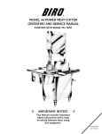
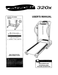
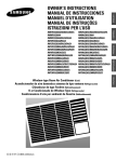
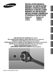
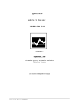
MODEL 922
MODEL
922
OPERATION AND SERVICE MANUAL
GRINDER PARTS LIST
GINDER PARTS LIST
GENERAL
INSTRUCTIONS
GENERAL INSTRUCTIONS
Starting with Serial Number C9861001
Starting with Serial Number C9861001
+
IMPORTANT SAFETY NOTICE
+
This Manual contains important
safety instructions which must
be strictly followed when using
this equipment.
C957-213
C957-213
213-3-04-12
213-2-09-15
TABLE OF CONTENTS
Page
NOTICE TO OWNERS AND OPERATORS . . . . . . . . . . . . . . . . . . . . . . . . . . . . . . . . . . . . . . . . . 1
SAFETY TIPS . . . . . . . . . . . . . . . . . . . . . . . . . . . . . . . . . . . . . . . . . . . . . . . . . . . . . . . . . . . . . . . 2
INSTALLATION . . . . . . . . . . . . . . . . . . . . . . . . . . . . . . . . . . . . . . . . . . . . . . . . . . . . . . . . . . . . . 3
UNCRATING AND SET UP . . . . . . . . . . . . . . . . . . . . . . . . . . . . . . . . . . . . . . . . . . . . . . . . . . . 3
MOTOR WIRING AND ELECTRICAL REQUIREMENTS . . . . . . . . . . . . . . . . . . . . . . . . . . . . . . 4
ELECTRICAL CONTACTORS . . . . . . . . . . . . . . . . . . . . . . . . . . . . . . . . . . . . . . . . . . . . . . . . . 5
WIRING DIAGRAMS . . . . . . . . . . . . . . . . . . . . . . . . . . . . . . . . . . . . . . . . . . . . . . . . . . . . . 5 & 6
OPERATION . . . . . . . . . . . . . . . . . . . . . . . . . . . . . . . . . . . . . . . . . . . . . . . . . . . . . . . . . . . . . . . . 7
TO PROCESS PRODUCT . . . . . . . . . . . . . . . . . . . . . . . . . . . . . . . . . . . . . . . . . . . . . . . . . . . . 7
CLEANING . . . . . . . . . . . . . . . . . . . . . . . . . . . . . . . . . . . . . . . . . . . . . . . . . . . . . . . . . . . . . . . . . 8
MAINTENANCE . . . . . . . . . . . . . . . . . . . . . . . . . . . . . . . . . . . . . . . . . . . . . . . . . . . . . . . . . . . . . 9
HIGH TORQUE DRIVE SYSTEM . . . . . . . . . . . . . . . . . . . . . . . . . . . . . . . . . . . . . . . . . . . . . . . 9
BEARINGS . . . . . . . . . . . . . . . . . . . . . . . . . . . . . . . . . . . . . . . . . . . . . . . . . . . . . . . . . . . . . . . 9
TRAY AND CASE PARTS DIAGRAM . . . . . . . . . . . . . . . . . . . . . . . . . . . . . . . . . . . . . . . . . . . . . . 10
TRAY AND CASE PARTS LIST AND PARTS ORDERING. . . . . . . . . . . . . . . . . . . . . . . . . . . . . . . 11
BOWL, FRAME AND MOTOR PARTS DIAGRAM. . . . . . . . . . . . . . . . . . . . . . . . . . . . . . . . . . . . . 12
OPERATOR'S SIGNATURE PAGE . . . . . . . . . . . . . . . . . . . . . . . . . . . . . . . . . . . . . . . . . . . . . . . . 13
LIMITED WARRANTY . . . . . . . . . . . . . . . . . . . . . . . . . . . . . . . . . . . . . . . . . . . . . . . . . . . . . . . . . 14
NOTICE TO OWNERS AND OPERATORS
BIRO’s products are designed to process food products safely and efficiently. Unless the operator is properly trained and supervised, however, there is the possibility of a serious injury. It is the
responsibility of the owner to assure that this machine is used properly and safely, strictly following
the instructions contained in this Manual and any requirements of local law.
No one should use or service this machine without proper training and supervision. All operators should be thoroughly familiar with the procedures contained in this Manual. Even so BIRO
cannot anticipate every circumstance or environment in which its products will be used. You, the
owner and operator, must remain alert to the hazards posed by the function of this equipment –
particularly the ROTATING GRINDING WORM, which can severely injure an inattentive operator
amputating fingers and limbs. No one under eighteen (18) years of age should operate this equipment. If you are uncertain about a particular task, ask your supervisor.
This Manual contains a number of safe practices in the SAFETY TIP section. Additional warnings are placed throughout the Manual. Warnings related to your personal safety are indicated by:
OR
Warnings related to possible damage are indicated by:
BIRO also has provided warning labels on the equipment. If any warning label or Manual becomes misplaced, damaged, or illegible, please contact your nearest Distributor or BIRO directly
for a replacement.
Remember, however, this Manual or the warning labels do not replace the need to be alert and
to use your common sense when using this equipment.
This Manual applies to machines with serial number C9861001 and higher.
- NOTE“A copy of this manual is included with each MODEL 922 GRINDER.”
“The descriptions and illustrations contained in this manual
are not binding. The manufacturer reserves the right to
introduce any modification without updating the manual.”
1
SAFETY TIPS
ROTATING GRINDING WORM
TO AVOID SERIOUS PERSONAL INJURY
NEVER Touch This Machine Without Training and Authorization By Your Supervisor.
NEVER Place Hands Into Machine Input or Output Openings.
NEVER Open Machine During Operation.
ONLY Use a Qualified Electrician to Install Electrical Connections According to Local Building
Codes: Machine MUST Be Properly Grounded.
ALWAYS Connect to Proper Voltage & Phase.
ONLY Install on Level, Non-Skid Surface in a Clean, Well-Lighted Work Area Away From
Children and Visitors.
NEVER Use This Machine For Non-Food Products.
NEVER Operate Machine With Tray And/Or TrayGuard Removed or Magnetic Safety Swtich
By-Passed.
ALWAYS Turn Off, Unplug From Power Source and Perform Lockout/Tagout Procedure to This
Machine BEFORE Attempting to Unjam or Unclog, Cleaning or Servicing.
NEVER Leave Machine Unattended While Operating.
NEVER Alter This Machine From its Original Form as Shipped From Factory. DO NOT Operate
Machine With Parts Missing.
PROMPTLY REPLACE Any Worn or Illegible Warning Labels.
ALWAYS Read Operation and Service Manual BEFORE Operating, Cleaning or Servicing.
USE ONLY BIRO Parts and Accessories Properly Installed.
2
INSTALLATION
TO AVOID SERIOUS PERSONAL INJURY
PROPERLY INSTALL EQUIPMENT IN ADEQUATE WORK AREA
ALWAYS Use Qualified Technician and Electrician for Installation.
ALWAYS Connect to Proper Voltage & Phase.
ALWAYS Install Equipment in Work Area with Adequate Light and Space Away From Children
and Visitors.
ONLY Operate on a Solid, Level, Non-Skid Surface.
NEVER Bypass, Alter, or Modify This Equipment in Any Way From Its Original Condition.
NEVER Operate With Tray And/Or Tray Guard Removed or Manetic Safety Switch By-Passed.
NEVER Operate Without all Warning Labels Attached and Owner/Operator Manual Available to
the Operator.
UNCRATING AND SET UP
1. Read this Manual thoroughly before installation and operation. Do not proceed with installation and operation if
you have any questions or do not understand anything in this Manual. Contact your local Distributor, or BIRO
first.
2. Install machine on a level, solid, non-skid surface in a well-lighted work area away from children and visitors.
3. This machine is complete except for a knife and plate. The grinding bowl assembly is packed separately in the
crate. Remove the grinding bowl assembly from the carton. Disassemble the grinding bowl. Assemble the
grinding bowl only into the front of the grinder. Insert and screw in tight the bowl lock handle under the grinding
bowl. Be sure that the back flange of the grinding bowl is tight against the front of the machine. Do not install
grinding worm at this time.
4. Install the feed tray to the top of the grinder. After checking and making sure the power supply is correct, plug in
your machine. NEVER OPERATE MACHINE WITHOUT TRAY INSTALLED. (Machine will not run with tray
removed.)
5. Machine must be properly grounded. Use qualified electrician to install according to building codes.
6. Pushbuttons that activate the internal on/off switch are located on the front of the machine. The interlock safety
switch is mounted inside the machine case toward the front and will break contact with the magnetic starter
should the tray be removed.
3
7. Push the green “ON” button. CHECK THE ROTATION OF THE WORM DRIVE SHAFT. ROTATION MUST
BE COUNTER-CLOCKWISE as indicated by the rotation decal affixed to the grinding bowl. ROTATION MUST
ONLY BE CHECKED WITH THE GRINDING WORM REMOVED, otherwise serious irreparable damage may
occur to grinding components. Push red “STOP” button.
8. If machine runs clockwise (backwards), it must be rewired to correct rotation, otherwise serious irreparable
damage may occur to grinding components.
9. Insert worm assembly into grinding bowl, place knife (sharp edges out) onto the square end of the worm
assembly. The breaker plate slides over the worm knife drive pin, and is held from rotating by a pin in the
grinding bowl. Put on the retaining ring.
ONLY HAND TIGHTEN RETAINING RING
For best results, use knife and plate as a set. Do not operate machine for any period of time without product
in the grinding bowl. This will cause heating and dulling of the knife and plate.
10. Check placement of all warning labels and Manual. Machine is now ready for trained operators to process
product.
11. Contact your local Distributor or BIRO directly if you have any questions or problems with the installation or
operation of this machine.
MOTOR WIRING AND ELECTRICAL REQUIREMENTS
(1) Interchange of current is made in motor outlet box. Leads are properly marked. Changing instructions are
on the motor plate or motor outlet box. Electrical contactor mounted on machine frame must also be
changed to match motor voltage.
(2) All grinders are wired for the voltage as ordered. Be sure motor specifications (voltage, cycle, phase) match
power supply line. Be sure line voltage is up to specification.
(3) Electrical connections to be in accordance with safety codes and National Electrical Code.
(4) Rated voltage of the unit shall be identical with full supply voltage.
(5) Voltage drop on the supply line shall not exceed 10% of full supply voltage
(6) The feederline conductor size in the raceway from the branch circuit to the unit must be correct to assure
adequate voltage under heavy starting and short overload conditions.
(7) The BIRO Manufacturing Company is not responsible for permanent wiring, connection or installation.
NOTE TO OWNER AND ELECTRICIAN: IF THIS MACHINE IS NOT CORD
AND PLUG CONNECTED TO THE ELECTRICAL SUPPLY SOURCE, THEN IT
SHOULD BE EQUIPPED WITH, OR CONNECTED TO, A LOCKABLE,
MANUALLY-OPERATED DISCONNECT SWITCH (OSHA 1010.147).
ELECTRICAL CONTACTORS
(1) All 1 HP motors are dual voltage and can be changed according to wiring diagram on motor nameplate.
(2) Be sure Contactor voltage matches voltage of motor.
(3) Failure to use proper Contactor for motor voltage will cause irreparable damage to contactor.
(4) Install proper plug on power cord for voltage used.
4
ELECTRICAL CONTACTORS
(1) All 1 HP motors are dual voltage and can be changed according to wiring diagram on motor nameplate.
(2) Be sure Contactor voltage matches voltage of motor.
A. Item No. C903-922 Contactor
1HP, 104-60-1
1HP, 115-60-1
1HP, 380/415/440-50/60-3 with C904 transformer
B. Item No. C903-1-922 Contactor
1HP, 220-50/60-3
1HP, 208/230-60-1
1HP, 240-50-1
11 2HP, 230-60-1
(3) FAILURE TO USE PROPER CONTACTOR FOR MOTOR VOLTAGE WILL CAUSE IRREPARABLE DAMAGE
TO CONTACTOR.
(4) Install proper plug on power cord for voltage used.
WIRING DIAGRAMS
MOTOR CONNECTION FOR
#C930-4 BALDOR MOTOR 220V/1PH/60HZ
1 to T1 / 4-5 to T2 / 2-3-8 TOGETHER
5
WIRING DIAGRAMS
6
OPERATION
ROTATING GRINDING WORM
TO AVOID SERIOUS PERSONAL INJURY
ONLY Properly Trained Personnel Should Use This Equipment.
NEVER Place Hands Into Machine Input or Output Openings.
NEVER Open Machine During Operation.
DO NOT Wear Gloves While Operating.
DO NOT Tamper With, Bypass, Alter, or Modify This Equipment in Any Way From Its Original
Condition.
NEVER Operate Machine With Tray And/Or Tray Guard Removed or Magnetic Safety Switch
By-Passed.
ALWAYS Turn Off, Unplug From Power Source and Perform Lockout/Tagout Procedure to This
Machine Before Unjamming, Unclogging, Cleaning or Servicing.
NEVER Leave Unattended While Operating.
NEVER Operate Without All Warning Labels Attached and Owner/Operator Manual Available to
the Operator.
A. TO PROCESS PRODUCT
1. Before starting grinder, have meat stomper within easy reach and container for receiving ground product at
output end of grinding bowl.
2. Push the green “ON” button. Look down grinder bowl and make certain grinding worm is turning in the
proper direction (counter-clockwise).
3. Carefully push unground product to top opening of grinding bowl and let drop to grinding worm. Product will
then be ground out.
DO NOT REACH DOWN BOWL OPENING
4. Use meat stomper to assist any product that should “bridge up” in grinding bowl opening.
5. When finished grinding push the red “OFF” button and unplug grinder from power source and perform
lockout/tagout procedures.
7
CLEANING
ROTATING GRINDING WORM
TO AVOID PERSONAL INJURY
ALWAYS Turn Off, Unplug From Power Source and Perform Lockout/Tagout Procedure to This
Machine BEFORE Cleaning or Servicing.
ONLY Use Recommended Cleaning Equipment, Materials and Procedures.
NEVER Spray Water or Other Liquid Substances Directly at Motor, Power Switch or any Other
Electrical Components.
ALWAYS Thoroughly Clean Equipment at Least Daily.
CLEANING THE BIRO MODEL 922 GRINDER
1. Disconnect grinder from power source and perform lockout/tagout procedures.
2. Remove the feed tray.
3. Remove grinding bowl end ring, breaker plate, knife and grinding worm and the grinding bowl.
DO NOT SPRAY DIRECTLY AT ELECTRICAL COMPONENTS
4. Machine is now ready to be cleaned using warm soapy water and rinsed with clean water. Machine may be
cleaned by power spray washing, taking care to not spray directly at any electrical controls.
5. After machine has been cleaned and allowed to air dry, all exposed metal surfaces should be coated with a good
food grade light oil or grease.
CLEANING THE BOWL - RING AND WORM
CARE OF TIN COATED PRODUCTS
(DO’S AND DON’TS)
1. Do not use abrasive cleaning materials, such as brillo pads or metal scrapers. Tin is a soft metal
and should be cleaned with a soft cloth and dried.
2. Do not use a cleaning agent containing a high percentage of free alkali or acid.
3. Do not use a detergent containing a high percentage of tri-sodium phosphate or meta-silicate.
Tin is reactive to both.
4. Rinse well and dry thoroughly after washing to remove agents that may be reactive to tin.
5. If sterilizing agent containing chlorine is used, the tinned surface must be thoroughly rinsed.
Chlorine is corrosive to tin.
6. Dry thoroughly after rinsing and store in a dry environment.
7. If water is exceptionally hard, drying will be necessary to prevent spotting.
8
MAINTENANCE
ROTATING GRINDING WORM
TO AVOID SERIOUS PERSONAL INJURY
ALWAYS Turn Off, Unplug From Power Source and Perform Lockout/Tagout Procedure to This
Machine BEFORE Servicing.
NEVER Touch This Machine Without Training and Authorization By Your Supervisor.
NEVER Place Hands Into Machine Input or Output Openings.
NEVER Bypass, Alter, or Modify This Equipment in Any Way From Its Original Condition.
PROMPTLY REPLACE Any Worn or Illegible Labels.
USE ONLY GENUINE BIRO Parts and Accessories Properly Installed.
A. HIGH TORQUE DRIVE SYSTEM
The Model 922 is driven by a High Torque Drive system for power transmissions.
“No Lubrication” is required (in fact) be sure no lubricant comes in contact with the sprockets or belt.
To insure a long life to the drive components:
1. Be sure the motor shaft and main drive shaft are parallel.
2. Be sure sprockets are in alignment.
3. Proper HTD belt tension is 3 32" on one side.
Tension should be checked every six (6) months.
B. BEARINGS
1. The main bearings are sealed for life. No need to lubricate.
2. Lubricate the motor bearings once a year with bearing grease.
9
TRAY AND CASE PARTS
10
TRAY
CASEPARTS
PARTSLIST
LIST
TRAY AND
AND CASE
NOTE: SPECIFY
SPECIFY MODEL
MODEL &
& SERIAL
SERIAL NUMBER
NUMBER WITH
WITHORDERING
ORDERINGPARTS
PARTS
NOTE:
C611-1
Rubber
Grommet
C611-1
Rubber
Grommet
C627-1
Voltage
wiring wiring
(decal) (decal)
C627-1
Voltage
Cord
for 3 Phase,
C645C645
Cord for
3 Phase,
14/4 SO14/4 SO
C645-1
Cord
for
1
Phase,
C645-1
Cord for 1 Phase, 14/3 SO14/3 SO
5
3
C649
Case
base ⁄1screw,
C649
Case to
baseto
screw,
6-18 x5 16⁄4-18 ´ 3 4
C906-1
Stomper
C906-1
Stomper
C906-1-SLD
Solid stomper
C906-1-SLD
Solid stomper
C908
Tray attachment
pin
C908
Tray attachment
pin
C913
Tray
attachment
C912-1A
Tray assembly w/guard &bracket
magnet, complete – Latch type
C938SFT
Tray guardbracket
(not sold
separately)
C913-1
Tray attachment
– Latch
Type ORDER C912A
C954
Safety
screen
C938SFT
Tray guard only (not sold separately) ORDER C938SFTA
C957-213
General
instruction
manual
(not shown)
C938SFTA
Tray guard
assembly
w/spacers
& fasteners,
must be welded by installer
C977
SS standoff for tray guard
C954
Safety screen
C980-3
Case cover
C957-213
General instruction manual (not shown)
C980-4
Case side strip (not sold separately) ORDER
C977
SS standoff for tray guard
C980A
C980-3
Case cover
C983-1
“Start” legend plate
C980-4
Case side
striplegend
(not sold
separately) ORDER C980A
C983-2
“Stop”
plate
C983-1
“Start”
legend
plate
HN15S
Hex nut, 1 4-20, SS
C983-2
“Stop”Model
legendand
plateSerial Number plate, (S/N required)
H333
1
HN15S
Hex nut,
-20, SS
H372
Hex ⁄4head
cap screw, 1 4-20 ´ 1 2
H333
ModelAluminum
and Serial Number
plate,S/N
(S/Nplate
required)
H374-1
pop
1 rivet for
1
H372
Hex head
cap screw,
⁄4-20 x ⁄2 switch, to 230V, same as
H442
Magnet
safety interlock
H374-1
Aluminum
pop rivet for S/N plate
42MC-Y64
H442
Magnet
safety interlock
switch, to
230V,230V
same to
as 42MC-Y64
H442-1
Magnet
safety interlock
switch,
600V
H442-1
Magnet
safetypush
interlock
switch,
230V to 600V
H482-1
Green
button
assembly
H482-1
GreenRed
pushpush
button
assembly
H482-2
button
assembly
1 , SS
LW10S
Lockbutton
washer,
H482-2
Red push
assembly
4
1
MC-410P Lock washer,
Bowl instructions
LW10S
⁄4, SS
16163A
Hold down clip, welded
MC-410P
Bowl instructions
42MC-441
Warning
16163A
Hold down
clip,label
welded
42MC-Y20-8
Magnet,
42MC-441
Warning label (not sold separately)
42MC-Y25-6Magnet,
Tray
locator
and rear hold down
42MC-Y20-8
(not
sold separately)
1 -20 ´ 1
42MC-Y25CB
Carriage
bolt,
4
2
42MC-Y25-6
Tray locator and rear hold
down
1 safety1interlock switch, to 230 volt
42MC-Y64
Magnetic
42MC-Y25CB Carriage bolt, ⁄4-20 x ⁄2
42MC-Y70 Magnetic
Safety
switch
bracket
42MC-Y64
safety
interlock
switch, to 230 volt
42MC-Y71
Hold
down
latch
42MC-Y70
Safety switch bracket
42MC-Y72
Self retaining nut
42MC-Y71
Hold down latch
42MC-Y73
Green start push button assembly
42MC-Y72
Self retaining nut
42MC-Y74
Red stop push button assembly
42MC-Y73
Green start push button assembly
42MC-Y75
“Start” legend plate
42MC-Y74
Red stop push button assembly
42MC-Y76
“Stop” legend plate
42MC-Y75
“Start”Warning
legend plate
H653-E
label, English
42MC-Y76
“Stop”
legend
H653-SP
Warningplate
label, Spanish
H653-E
Warning label, English
H653-SP
Warning label, Spanish
ASSEMBLIES
C912A
C912-1A
C912A
C912-1A
C980A
C980A
Tray assembly w/guard & magnet complete –
ASSEMBLIES
spring type,
old style
Tray assembly w/guard & magnet complete –
Tray assembly
w/ guard & magnet complete – spring type, old style
latch type
Tray assembly
w/ guard & magnet complete – latch type
Case assembly
Case assembly
11
BOWL, FRAME & MOTOR PARTS
BOWL, FRAME & MOTOR PARTS LIST
NOTE: SPECIFY MODEL & SERIAL NUMBER WHEN ORDERING PARTS
CC22OP
CK22
CP22
CR22
C600
C617
C622
C629
C632
C638
C662
C664
C664-1
C670
C903-922
C903-1-922
C904
C909
C910
C910-1
C910K
C910-1K
C914
C915
Grinding bowl
Knife drive pin, 1" round
Bowl pin, 316 ´ 11 8
End retaining ring
Bowl locator pin, 5 16-18
Key, 1 4 ´ 2
Shaft collar lock pin
Rear main bearing
Retaining ring
Motor stud, 5 16 ´ 13 8, motor/frame
Heli-coil, 1 2"
Jam nut, 5 16-18, 50 HZ
Hex nut, 5 16-18, 60 HZ
Worm drive shaft
Contactor, 110 Volt
Contactor, 220 Volt
Transformer, 380/415 Volt only
Upper shaft collar
Order C910K
Order C910K after s/n 2388, C910K-1
before s/n 2388
Main drive shaft kit
all 1HP, 11 2HP after s/n 2388
Main drive shaft kit
11 2HP before s/n 2388
Aluminum grinder frame
Rubber foot, 1", 1 4-20 thread
C916
C919
C919-1
C920A
C921
C921-1
C929
C930-2
C930-3
C930-4
C930-5
C930-6
C931
C950
C981
C981-1
H370
H465
LW25S
Flatwasher
Main drive gear, 148T, 60 HZ
Main drive gear, 122T, 50 HZ
Motor pinion, 28T, 50/60 HZ, 1&3PH
HTD belt, 800-5M-30MM, 60 HZ
HTD belt, 710-5M-30MM, 50 HZ
Front main bearing
Motor, 1HP, 220/440-50/60-3
Motor, 1HP, 104/208-60-1
Motor, 1HP, 115/230-60-1
Motor, 1HP, 240-50-1
Motor, 11 2HP, 208/230-60-1
Motor key, 316 ´ 316 ´ 13 8
Shaft spacer, 5 16tk
End clip for din rail
Din rail
Hex nut, 5 16-18, (top of motor stud)
Hex head screw, 3 8 -16 ´ 3 4
Lock washer 3 8
ASSEMBLIES
CC22OPA
CS22A
C601A
12
Open bowl assembly
Worm assembly
Bowl lock handle assembly
OPERATOR’S SIGNATURE PAGE
WARNING
READ AND UNDERSTAND THIS ENTIRE
MANUAL BEFORE SIGNING BELOW
MY SIGNATURE ATTESTS THAT I HAVE COMPLETELY READ AND UNDERSTAND THIS
MANUAL. I REALIZE THAT THIS MACHINE, IF OPERATED CARELESSLY, CAN CAUSE SERIOUS INJURY TO MYSELF AND OTHERS.
NAME (PRINT)
SIGNATURE
13
SUPERVISOR’S
INITIALS
DATE
LIMITED WARRANTY:
WARRANTY: The BIRO Manufacturing Company warrants that Model 922 Grinder will be free
from defects in material and workmanship under normal use and with recommended service.
BIRO will replace defective parts, which are covered by this limited warranty, provided that the defective parts are authorized for return, shipping charges prepaid, to a designated factory for inspection and/or testing.
DURATION OF WARRANTY: The warranty period for all parts covered by this limited warranty is
one (1) year from date of Inspection/Demonstration advised on the returned Warranty Registration
card, or eighteen (18) months from original factory ship date, whichever occurs first, except as
noted below.
PARTS NOT COVERED BY WARRANTY: The following are not covered by this limited warranty:
wearable parts in the grinding system such as bowl, worm drive shaft, ring, worm, and knife drive
pin. This limited warranty does not apply to machines sold as used, rebuilt, modified,or altered
from the original construction in which the machine was shipped from the factory. (Water contaminated electrical systems are not covered under this limited warranty.) BIRO is not responsible
for electrical connection of equipment, adjustments to switch components or any other electrical
requirements, which must be performed only by a certified electrician. BIRO is also not responsible for service charges or labor required to replace any part covered by this limited warranty or for
any damages resulting from misuse, abuse, lack of proper or recommended service.
EXCLUSION OF WARRANTIES AND LIMITATION OF REMEDIES: BIRO gives no warranties
other than those expressly stated in this limited warranty. THE IMPLIED WARRANTY OF MERCHANTABILITY, THE IMPLIED WARRANTY OF FITNESS FOR PROCESSING OF FOOD PRODUCTS, AND ALL OTHER IMPLIED WARRANTIES ARE SPECIFICALLY EXCLUDED. BIRO IS NOT
LIABLE FOR CONSEQUENTIAL OR INCIDENTAL DAMAGES, EXPENSES, OR LOSSES. THE
REMEDIES PROVIDED IN THIS BIRO LIMITED WARRANTY ARE PURCHASER’S SOLE AND EXCLUSIVE REMEDIES AGAINST BIRO.
REGISTRATION CARDS: You must sign, date and complete the warranty registration card supplied with each machine. The warranty card must be returned to The Biro Manufacturing Company for proper registration. If no warranty card is returned to BIRO, the warranty period will begin
from the date the machine was originally shipped from the factory.
HOW TO GET SERVICE:
1. Contact the entity from whom you purchased the machine; or
2. Consult the yellow pages of the phone directory for the nearest authorized dealer; or
3. Contact BIRO Mfg. Co. for the authorized service entity (250 plus worldwide) in your area.
THE BIRO MANUFACTURING COMPANY
1114 Main Street
Marblehead, Ohio 43440-2099
Ph. 419-798-4451
Fax 419-798-9106
E-mail: [email protected]
Web: http://www.birosaw.com
ITEM
NO. C957-213
ITEM NO. C957-213
Form
922-213-2-09-15
PPD
Form No.
No. 922-213-3-04-12
ENG.
COMM
14