1
Issue 7
V-9940
EXPANDABLE STATION LEVEL PAGE ADAPTER
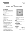
INTRODUCTION
The V-9940 is an Expandable Station Level
Page Adapter designed to provide ring trip and
page access circuitry for use on standard device
telephone lines. These instructions contain the
specifications and information necessary to
install, operate and maintain the V-9940
Expandable Station Level Page Adapter.
IMPORTANT: Please review dip switch
settings (page 3) for equipment suitability.
FCC Information
Features
When installing the V-9940, contact the local
Telephone Company and give them the
following information:
• The telephone number of the line to which
the V-9940 will connect;
• The FCC Registration #: BAF9I7-13957OT-N;
• The ringer equivalence number: 1.1A
•
•
•
•
•
If the V-9940 is disconnected from its present
line, contact the local Telephone Company to
make them aware of the change.
•
•
•
•
•
•
•
•
•
•
•
Telephone Company Procedures: the goal of
the telephone company is to provide the best
service possible. In order to do this, it may
occasionally be necessary for them to make
changes in their equipment, operations or
procedures. If these changes potentially affect
the service or the operation of customer
equipment, the Telephone Company will give
written notice to allow any changes necessary to
maintain uninterrupted service.
Ring trip on first ring
600 Ohms output; 8 Ohms output with AGC
Multiple units may be used for multi-zone
paging with all call behind a PABX
Use with Valcom multi-zone page control
unit for multi-zone paging Centrex or C. O.
lines (DTMF signaling only)
Use with Valcom handsfree page units for
talkback paging
Background music input
Open loop detect reset
Audio sensing circuit for reset
Time out reset
Manual reset
Answer verification tone
All call override tone
Battery reversal indicator
Auxiliary Make/Break contact
Built in 66 type connection block
Complies with UL 145
SPECIFICATIONS
Access Methods
•
•
•
Centrex numbers
Loop start and ground start central office
lines
PABX station numbers
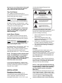
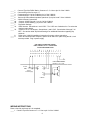
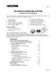
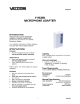
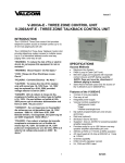
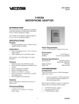
Figure 1 depicts a block diagram of a typical
PABX installation.
1
947740
second after ring trip
Audio Sense Release:
4, 8, 16, 32 or 64
seconds after audio drops below -22dBm
Time Out Release: 1, 4, 8, 16, 32 or 64 seconds
Manual Reset:
25ms ground
Output 1:
Impedance:
600 Ohms
Page Level Output Level: Input Level
-1dB
Music Level Output Level: Input Level
Output 2:
Impedance:
8 Ohms
Page Level:
-10dBm
Music Level:
-17dBm
Music Source:
8 to 600 Ohms
-10 to -18dBm
Answer Verification Tone: 500Hz: 250ms On;
250ms Off
Form C Contacts:
30VDC, 2.0 Amps or
125VAC, 1.0 Amp
NOTE: When used with a PABX, the PABX
must not return any tones to the called party
after calling party disconnect on a station to
station call.
ZONE 1 IN
T
IN
R
ALL CALL IN
8 OHM OUT
ALL CALL AUDIO
ZONE 2 IN
T
IN
R
ALL CALL IN
8 OHM OUT
ALL CALL AUDIO
ALL CALL IN
VALCOM ONE-WAY
AMPLIFIED SPEAKER
ASSEMBLIES
T
IN ALL CALL OUT
8 OHM OUT
R
FIGURE 1
BLOCK DIAGRAM OF A TYPICAL PABX INSTALLATION
Capacity
•
•
•
•
DESIGN
Each V-9940 provides one zone of paging
(when connected to its own PABX station
number).
Use a V-9940 and a station number per
zone for multi-zone paging behind a PABX.
An additional station number and V-9940
may be used to provide all call or override in
a one-way multi-zone system behind a
PABX.
One V-9940 may be used with a Valcom
multi-zone page unit to provide up to 36
zones of paging on Centrex or central office
lines (DTMF signaling only).
General
The Valcom V-9940 Expandable Station Level
Page Adapter is designed to provide access to
paging from a standard PABX station number, a
Centrex number or a Central Office line. It
should not be used on coin service lines or party
lines. The V-9940 may be directly connected to
Valcom One-Way Amplified speaker assemblies
or may be used in conjunction with Valcom one
zone or multi-zone page adapters. The
following sections describe possible
arrangements and detail the equipment
required.
Dimensions/Weight
•
•
When One-Way Amplified Speaker Assemblies
are specified, consult the Valcom catalog for the
style desired. Once the style and quantity of
speakers are determined, select the appropriate
power supply after referring to the Valcom
One-Way Paging VSP or the Marketing Guide.
8.20" H x 4.55" W x 2.30" D
(20.83cm x 11.56cm x 5.84cm)
1.7 lbs. (0.77 kg)
Power Requirements
-21.5 to -26VDC "B" Battery, 200mA maximum
(Valcom VP-624B Class 2 power source
recommended).
PABX Station Level Paging
NOTE: Before proposing Station Level
Paging, perform the following test:
Environment
Temperature:
Humidity:
0 to +50°C
0 to 85% (non-precipitating)
1. Dial between two stations on the PABX and
answer the call.
2. Have the called party keep listening while
the calling party hangs up.
3. After calling party release, what does the
called party hear?
Specifications
Tip and Ring Input:
Voltage for Ring Trip:
Ring Trip Timing:
Open Loop Detect:
600 Ohms
75-105VAC
150ms
If the PABX IMMEDIATELY returns any type of
tones to the called party (dial tone, reorder tone,
150ms starting 1
2
It may be added to the V-119RTVA with a
V-1118 and to the V-136RTHF with a V-1134.
See Note.
etc.) then STATION LEVEL PAGING CAN NOT
BE USED. Consult the Valcom catalog for an
appropriate trunk level page adapter. If there is
silence of at least 10 SECONDS before any
tones are returned, then one-way paging may
be used. If the line REMAINS SILENT for at
least 1 and 1/2 minutes after disconnect, then
one-way or talkback paging may be used.
• One Zone of Talkback Paging:
One Zone of Talkback Paging requires one
Centrex or C. O. Line, one V-9940, one
V-9941A, one zone talkback unit, 45 Ohm
talkback speakers (maximum 2) and a VP-624B
power supply. See Note.
If the type of paging desired is possible on a
station level of the PABX, continue in this
section to determine equipment required.
• Multi-Zone Talkback Paging:
Multi-Zone Talkback Paging requires one
Centrex or C. O. Line, one V-9940, a dial select
page control unit (V-2003AHF, V-2006AHF,
V-1109RTHF, V-119RTHF or V-136RTHF),
appropriate talkback speakers and a -24VDC
power supply.
• One Zone of One-Way Paging:
This arrangement requires one PABX station
number, one V-9940 page adapter, appropriate
Valcom One-Way Amplified Speaker
Assemblies and a -24VDC power supply.
• Multi-Zone One-Way Paging with All Call:
This arrangement requires a PABX station
number and V-9940 for each zone and an
additional number and V-9940 for all call.
One-Way amplified Speaker Assemblies and 24VDC power supplies are also required.
NOTE: One-way All Call is included with the
V-2003AHF, V-2006AHF, and V-1109RTHF. It
may be added to the V-119RTHF with a
V-1118 and to the V-136RTHF with a V-1134.
See Note.
Wiring of each arrangement is covered in the
Installation Section.
• One Zone of Talkback Paging:
This arrangement requires one V-9940, one
V-9941A, one-zone talkback unit, appropriate 45
Ohm talkback speakers (maximum 2), and a
VP-624B power supply. See Note.
NOTE: When using the V-9940 Expandable
Station Level Paging Adapter to access
multi-zone or handsfree control units, it
should be understood that the quality and
noise characteristics of the C . O. Line circuit
may affect the operation of this equipment
adversely.
Centrex or C. O. Line Access to
Paging:
NOTE: Although the V-9940 will work on
both loop start or ground start lines, when
using Centrex service, ground start lines
provide better security against returned
tones. In addition, Centrex lines should be
optioned for cut OFF when disconnect
occurs.
Dip Switch Settings
The dip switch settings are crucial to proper
operation of the V-9940 and are different for
each application. The dip switches select the
way the V-9940 releases from the line and how
long a page may be made. There are three
ways the V-9940 releases from the line that are
dependent on dip switch settings:
• One Zone of One-Way Paging:
One zone of One-Way Paging requires one
Centrex or C. O. Line, a V-9940, One-Way
Amplified Speaker Assemblies and a -24VDC
power supply.
Open Loop Detect
The V-9940 detects a 150ms or longer break in
loop current one second after ring trip and
release from the line. The one second delay in
line supervision is allowed due to the instability
of some C. O. and Centrex lines for the first
second after ring trip.
Dip switch settings: Set dip switches 1 and 8
"ON", dip switches 2 through 7 "OFF".
• Multi-Zone One-Way Paging:
Multi-zone One-Way Paging requires one
Centrex or C. O. Line, a V-9940, a dial select
page control unit (V-2003A, V-2006A,
V-1109RTVA, V-119RTVA or V-136RTHF),
appropriate One-Way Amplified Speaker
Assemblies and a -24VDC power supply.
NOTE: All Call is included with the V-2003A,
V-2006A and the V-1109RTVA.
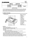
NOTE: This setting provides unlimited page
length. In certain instances a default timeout
release is recommended. To select a default
3
110-18 of the National Electrical Code,
ANSI/NFPA No. 70.
timeout, turn one of dip switches 2 through 7
"ON". Refer to Figure 4 for the maximum
page length each dip switch allows.
CAUTION
Time Out Release
RISK OF ELECTRIC SHOCK
DO NOT OPEN
The V-9940 will release from the line a
pre-determined amount of time after ring trip as
determined by dip switch settings.
CAUTION: To reduce the risk of electric shock,
Do not remove cover.
No user serviceable parts inside.
Refer servicing to qualified service personnel.
Typical Applications: Access from a PABX
Station to one zone of talkback page (station
level access not normally used with talkback).
This symbol indicates that dangerous
voltage constituting a risk of electric
shock is present within this unit.
.
Dip Switch Settings: Set dip switches 1 and 8
"ON". Set one of dip switches 2 through 7 "ON"
to select the maximum page length.
This symbol indicates that there are
important operating and maintenance
instructions in the literature accompanying
this unit.
NOTE: This setting assigns a limited page
length. See PABX Station level Paging to
determine if the PABX is compatible for
station level page.
When using this equipment, basic safety
precautions should always be followed to reduce
the risk of fire, electric shock and injury to
persons including the following:
Audio Sense Release
1. Never install telephone wiring during a
lightning storm.
2. Never install telephone jacks in wet
locations unless the jack is specifically
designed for wet locations.
3. Never touch uninsulated telephone wires or
terminals unless the telephone line has
been disconnected at the network interface.
4. Use caution when installing or modifying
telephone lines.
The V-9940 will release from the line after a
pre-determined amount of time that silence is
detected as determined by dip switch settings.
Typical Applications: Access from a PABX
Station to one zone of one-way page or multiple
zones of one-way page using multiple PABX
stations and multiple V-9940s.
Dip switch settings: Set dip switch 1 "OFF", dip
switch 8 "ON". Set one of dip switches 2
through 7 "ON" to select the length of time the
unit stays active after last sensing audio.
(Normally dip switch 6 or 7 - for 8 or 4 seconds).
General
The following sections contain step-by-step
instructions for wiring the V-9940 and
associated Valcom equipment. If the results of a
test do not correspond with what is shown, DO
NOT PROCEED UNTIL THE PROBLEM HAS
BEEN CORRECTED.
NOTE: This setting provides unlimited page
length. See PABX Station Level Paging to
determine if the PABX is compatible for
station level page. When used with talkback
paging, the talkback audio may delay or
cancel the audio sense release.
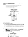
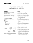
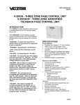
During installation, Figure 2 may be referred to
for location and numbering of punchdown block.
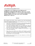
Refer to Figure 3 for punchdown block pinouts
and Figure 4 for dip switch settings.
In some special applications, a manual reset
can be used to provide release from the line by
providing a momentary ground to the manual
reset pin of the V-9940.
NOTE: To aid system testing and balancing,
be sure to set the individual volume controls
at approximately ½ volume when installing
one-way amplified speaker assemblies.
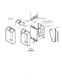
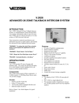
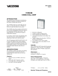
Mounting
INSTALLATION
Remove the metal mounting plate from the rear
of the V-9940 enclosure. Using two #6 ¾ inch
wood screws, mount the plate in a vacant space
on the backboard with the telephone system
common equipment. Both mounting holes
must be utilized to insure secure mounting
Regulatory Information
This equipment is to be installed only in
restricted access areas (dedicated equipment
rooms, equipment closets or the like) in
accordance with Articles 110-16, 110-17, and
4
of the unit. Provisions for mounting to a single
or double gang junction box are provided.
See Figure 5.
Open the V-9940 enclosure to allow access to
connections and option switches. Slide the rear
of the unit (contains the board) onto the
mounting plate. Lock enclosure to mounting
plate with screw provided. Make connections.
Replace cover and lock in place with #6 ½ inch
screws provided.
Power Connections
NOTE: Power is required for each V-9940
being used. If multiple units are used, power
for additional units may be multiplied from
pins 14 and 15 of a previous unit (pin 14 is
"+" and pin 15 is "-").
•
•
•
Figure 4 Dip Switch Settings
SW
1
2
3
4
5
6
7
8
Unplug power supply.
Connect -24VDC "B" battery (may be
referred to as "-" or "signal battery") from
power supply to pin 30 on V-9940 and "B"
ground "+" or "signal" ground) from power
supply to pin 29.
Connect -24VDC Ground from power supply
to telephone system Ground.
ON
OFF
1
ON
Time Out
Enable
1 Second
64 Seconds
32 Seconds
16 Seconds
8 Seconds
4 Seconds
Loop Detect
Enable
5 6 7 8
ON
OFF
•
1.
2.
3
•
Dip
Switches
8
OFF
Audio Sense
Enable
Not 1 Sec.
Not 64 Sec.
Not 32 Sec.
Not 16 Sec.
Not 8 Sec.
Not 4 Sec.
Loop Detect
Disable
1 2 3 4
Power Test:
a. Plug in power supply.
b. If power reversal LED is lit:
Unplug power supply.
Reverse connections on pins 29, 30.
Repeat step 5.
Unplug power supply.
PABX Connecting Arrangements:
NOTE: From the list below, determine the
arrangement being used and proceed to the
Figure indicated for step-by-step
instructions.
• One Zone of One-Way Paging: Go to
Figure 6.
• Multi-Zone One-Way Paging with All Call
(Multiple Talkpaths): Go to Figure 7.
• One Zone of Handsfree Paging: Go to
Figure 8.
Power
Reversal
Indicator
Punchdown
Block
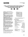
FIGURE 2
LOCATION AND NUMBERING OF
PUNCHDOWN BLOCK AND DIP SWITCHES
7
6
5
MAKE
8
STATIONARY
15 14 13 12 11 10 9
BREAK
600 OHM PAGE OUT
8 OHM PAGE OUT
MANUAL RESET
5
AUX GND TERM.
FIGURE 3 - PUNCHDOWN BLOCK PINOUTS
ALL CALL OUT
1
16
AUX -24VDC OUT TERM
15
30
4
3
2
1
WIRE TIE LOOP
WIRE TIE USED TO BUNDLE WIRES
ENTERING AND LEAVING TERMINAL AREA
TO REMOVE COVER
LOOSEN SCREW,
THEN ACTIVATE LATCH
WIREWAY OPENING
TO WALL PLATE AND
JUNCTION BOX
METAL WALL
MOUNTING
PLATE
.155 DIA. HOLES FOR MOUNTING TO
SINGLE OR DOUBLE GANG JUNCTION BOX
HOLE PATTERN MATCHES BOTH EURO
AND US JUNCTION BOXES
SNAP LATCH
1.5 x 2 WIRE ACCESS OPENING
TO JUNCTION BOX
CIRCUIT BOARD
HOUSING ASSEMBLY
SNAP LATCH
FOR COVER
PLASTIC
COVER
BRACKET
LOCKING
SCREW
FIGURE 5
MOUNTING
EXPLODED VIEW
6
Centrex or C. O. Connecting Arrangements
From the list below, determine the arrangement being used and proceed to the Figure indicated for
instructions.
• One Zone of One-Way Paging: Go to Figure 5.
• Multi-Zone One-Way Paging will All Call (Multiple Talkpaths): Go to Figure 6.
• Multi-Zone One-Way Paging (1 Talkpath): Go to Figure 8.
• One Zone Talkback Paging: Go to Figure 7.
• Multi-Zone Talkback Paging: Go to Figure 8.
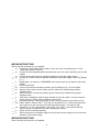
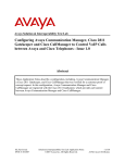
FIGURE 6
ONE ZONE OF ONE-WAY PAGING
PABX, CENTREX, OR C.O. LINE ACCESS
V-9940 CONNECTION BLOCK
8 7
6 5 4
3 2
1
15 14 13 12 11 10 9
30 29 28 27 26 25 24 23 22 21 20 19 18 17 16
PBX
R
-24Vdc -
T
GND
B BATTERY
B GROUND (+)
-24Vdc POWER
SUPPLY
VALCOM ONE-WAY
AMPLIFIED SPEAKER
ASSEMBLIES
WIRING INSTRUCTIONS
Place a check by each step as it is completed.
____ 1. Connect Tip of the PABX, Centrex or C. O. Line to pin 16 and Ring to Pin 17 of the V-9940.
____ 2. Connect Tip of the Valcom one-way amplified speaker assemblies being used to the V-9940
pin 8 and Ring to pin 9.
____ 3. Connect the Ground Lead from the speaker assemblies to the power supply "B" Ground (or
"+").
____ 4. Connect the -24VDC lead from the speaker assemblies to the power supply "B" Battery (or
"-").
____ 5. Connect the output of a low level music source (optional) to pins 21 and 22.
____ 6. Dip Switch Settings:
PABX: Switch 1 must be "OFF". Turn "ON" one of switches 2 to 7 to select the length of time
the unit stays active after last sensing audio (reset timing). SWITCH 8 MUST BE "ON".
Centrex or C. O. Line: Set Switches 1 and 8 "ON" and 2 through 7 "OFF". See section titled
"Dip Switch Settings" for additional information regarding dip switched.
____ 7. When connections are complete replace cover and lock in place using the #6 ½ inch screws
provided. Plug in power supply.
FIGURE 7
MULTI - ZONE ONE -WAY PAGING WITH
ALL CALL (MULTIPLE TALKBACK)
PABX, CENTREX, OR C.O. LINE ACCESS
7
15 14 13 12 11 10 9 8 7 6 5 4 3 2 1
30 29 28 27 26 25 24 23 22 21 20 19 18 17 16
Zone 1
Station
Number
WIRING INSTRUCTIONS
Place a check by each step as it is completed.
___ 1a. Connect Tip of the PABX station number for zone one to pin 16 and Ring to pin 17 of the
V-9940 being used for zone one.
___ 1b. Connect Tip of the amplified speaker assemblies for zone one to pin 8 and Ring to pin 9 of the
V-9940.
___ 1c. Connect the Ground lead of the speaker assemblies to the power supply Ground.
___ 1d. Connect the -24VDC lead of the speaker assemblies to the power supply -24VDC ("B" Battery
or "-").
___ 2.
Repeat Step 1 for each zone. REMEMBER, each zone requires its own station number and
V-9940.
___ 3.
All Call Connections:
___ 3a. Connect Tip of the All Call station number to pin 16 and Ring to pin 17 of the V-9940.
___ 3b. Strap from pin 9 of the all call V-9940 to pin 26 of each of the V-9940s being used for
individual zones.
____3c. Strap from pin 13 of the all call V-9940 to pin 28 of each of the V-9940s being used for
individual zones.
____ 4.
Music Input: Background music may be provided on a per zone basis. Connect a low level
source to pins 21 and 22 of each V-9940 to receive music.
____ 5.
Dip Switch Settings: Switch settings are the same for the individual zones and the all call.
____ 5a. PABX - Switch 1 must be "OFF". Turn "ON" one of switches 2 to 7 to select the reset timing
(the length of time the unit stays active after last sensing audio). Turn switch 8 "ON".
____ 5b. Centrex or C. O. Line - Set switches 1 and 8 "ON", 2 to 7 "OFF". See Section titled "Dip
Switch Settings" for additional information regarding dip switches.
____ 6.
Adjust volume at individual speakers.
____ 7.
When connections are complete, replace cover and lock in place using the #6 ½ inch screws
provided. Plug in power supply.
WIRING INSTRUCTIONS
Place a check by each step as it is completed.
8
____
____
____
____
____
____
____
____
____
____
1.
2.
3.
4.
5.
6.
6a.
6b.
7.
7a.
Connect Tip of the PABX Station, Centrex or C. O. Line to pin 16 of the V-9940.
Connect Ring of the line to pin 17.
Crossconnect pin 6 of the V-9940 to pin 1 of the V-9941A.
Crossconnect pin 7 of the V-9940 to pin 2 of the V-9941A.
Connect 45 Ohm talkback speakers (maximum 2) to pins 6 and 7 of the V-9941A.
V-9941A Power Connections:
Connect -24VDC Ground (+) to pin 3 of the V-9941A.
Connect -24VDC Battery (-) to pin 4 of the V-9941A.
Dip Switch Settings:
PABX Access: Set switches 1 and 8 "ON". Turn "ON" one of switches 2 to 7 to select the
maximum page length.
____ 7b. Centrex or C. O. Line access: Set switches 1 and 8 "ON". Set switches 2 through 7 all
OFF". See section titled "Dip Switch Settings" for additional information regarding dip
switches.
____ 8.
Refer to the V-9941A installation instructions for proper volume procedure.
____ 9.
When all connections are complete, replace cover and lock in place using the #6 ½ inch
screws provided. Plug in power supply.
FIGURE 8
ONE ZONE OF HANDSFREE PAGING
PABX, CENTREX, OR C. O. LINE ACCESS
V-9940 PUNCHDOWN BLOCK
15 14 13 12 11 10 9
8
7
6
5
4
3
2
1
30 29 28 27 26 25 24 23 22 21 20 19 18 17 16
T
R
PABX Station, Centrex
Number, or C. O. Line
-24 Vdc
GND
-24 Vdc
Power Supply
4
3
2
1
6
7
V-9941A
WIRING INSTRUCTIONS
Place a check by each step as it is completed.
____ 1. Connect Tip of the Centrex or C. O. Line to pin 16 of the V-9940.
9
____ 2. Connect Ring of the line to pin 17.
____ 3. Crossconnect pin 6 of the V-9940 to the Tip "WHITE/BLUE" of a Valcom multi-zone dial select
page control unit (such as the V-1109RTVA or V-1109RTHF).
____ 4. Crossconnect pin 7 of the V-9940 to the control unit Ring "BLUE/WHITE".
____ 5. Refer to the Installation Manual supplied with the control unit for speaker and power
connections.
____ 6. Refer to the Installation Manual supplied with the control unit for proper volume adjustment
procedures.
____ 7. Dip Switch Settings: Set dip switches 1 an 8 "ON". Set switches 2 to 7 all "OFF". See Section
titled "Dip Switch Settings" for additional information regarding dip switches.
____ 8. When all connections are complete, replace cover and lock in place using the #6 ½ inch screws
provided. Plug in power supply.
FIGURE 9
MULTI- ZONE ONE WAY OR HANDSFREE PAGING
CENTREX OR C. O. LINE ACCESS
V-9940 PUNCHDOWN BLOCK
15 14 13 12 11 10 9
8
7
6
5
4
3
2
1
30 29 28 27 26 25 24 23 22 21 20 19 18 17 16
T
R
Centrex Number
or C. O. Line
BL/WH
WH/BL
B Ground (+)
B Battery (-24VDC)
V/SL
SL/V
Zone
Outputs
-24VDC
Power Supply
Valcom Dial Select
Multi-Zone Page Unit
Speakers
(Type depends
on Control Unit)
OPERATION
Circuit Description
The V-9940, Station Level Page Adapter, has
three inputs: Tip and Ring from the line, music
and all call; and two outputs: 8 Ohm and 600
Ohm.
10
Any input will provide audio at both the 8 Ohm
and 600 Ohm outputs. Signals coming from the
8 Ohm output will be maintained 7dB below the
level of the paging (this is not user adjustable).
There is no modification of page or music
signals when using the 600 Ohm output. The
600 Ohm output also provides a loop on access
and may be used with loop start paging
equipment.
number is dialed, any paging in progress will be
overridden and an alert tone will be returned to
the overridden parties. If they remain on line, on
completion of the all call page, they will be
reconnected to their respective zones and all
timers will be reset, allowing a full page again on
each zone.
TECHNICAL ASSISTANCE
When trouble is reported, verify that power is
being supplied to the unit and there are no
broken connections. Check voltages for proper
polarity on the crossconnect block. Table 1
identifies symptoms of possible problems with
solutions. If a spare unit is available, continue to
troubleshoot by substituting the spare unit for
the suspected defective unit.
In the idle state, signals from the music input will
appear on both the 8 Ohm and 600 Ohm
outputs. On receipt of superimposed ring
generator on Tip and Ring, the V-9940 will be
activated and will place a loop across the station
Tip and Ring for ring trip. An answer verification
tone will then be returned to the calling party and
Tip and Ring audio will be connected to the 8
Ohm and 600 Ohm outputs.
Assistance in troubleshooting is available from
the factory. When calling, you should have a
VOM, several clip leads, a telephone test set
available and call from the job site. Call (540)
563-2000 or visit our website at
http://www.valcom.com.
After access, the reset circuitry is turned on. If
the unit is set for loop detect, it will ignore any
open loop conditions for the first second, then it
will release when it senses an open loop on Tip
and Ring lasting at least 150ms. If you are
using the audio sense reset, the unit will stay on
The V-9940 is not field repairable. Valcom, Inc.
line until sensing a lack of audio (-22dB or less)
maintains service facilities in Roanoke, VA.
for the period set by the dip switches. If using
Should repairs be necessary, attach the
the time out reset, the unit will stay on the line
company name, address, phone number,
for the preset length of time and then will reset,
contact person and the nature of the problem.
whether the page is complete or not. Upon
Send the unit to:
release, the music source is reconnected to the
Valcom, Inc.
outputs.
SIMPLIFIED SCHEMATIC
Repair and Return Dept.
All call, if connected, will override both the music
5614 Hollins Road
and page inputs. All call requires an additional
ALL CALL IN
Roanoke,
VA 24019-5056
CONTROL,
station port for access and must
be wired as
OPTION &
ALL CALL OUT
shown in Figure 6. When the allTIMING
call station
ACCESS
AUDIO
SENSE
CIRCUITS
MANUAL RESET
T
R
RING
DETECT
TONE
GEN.
XFORMER
LOOP
XFORMER
XFORMER
XFORMER
8 OHM
OUT
PREAMP
AGC
600 OHM OUT
MUSIC IN
K2
K3
ALL CALL
AUDIO IN
-24VDC
GROUND
MAKE
POWER
SUPPLY
STATIONARY
-12
-24
BREAK
VALCOM LIMITED WARRANTY
Valcom, Inc. warrants its products to be free from defects in materials and workmanship under conditions of normal use and service
for a period of one year from the date of shipment. The obligation under this warranty shall be limited to the replacement, repair or
11
refund of any such defective device within the warranty period, provided that:
1.
2.
3.
4.
5.
inspection by Valcom, Inc. indicates the validity of the claim;
the defect is not the result of damage, misuse or negligence after the original shipment;
the product has not been altered in any way or repaired by others and that factory sealed units are unopened (a service
charge plus parts and labor will be applied to units defaced or physically damaged);
freight charges for the return of products to Valcom are prepaid;
all units ‘out of warranty’ are subject to a service charge. The service charge will cover minor repairs (major repairs will
be subject to additional charges for parts and labor).
This warranty is in lieu of and excludes all other warranties, expressed or implied and in no event shall Valcom, Inc. be
liable for any anticipated profits, consequential damages, loss of time or other losses incurred by the buyer in connection
with the purchase, operation or use of the product.
This warranty specifically excludes damage incurred in shipment. In the event a product is received in damaged condition, the
carrier should be notified immediately. Claims for such damage should be filed with the carrier involved in accordance with the
F.O.B. point.
Headquarters:
Valcom, Inc.
5614 Hollins Road
Roanoke, VA 24019-5056
Phone: (540) 563-2000
Fax: (540) 362-9800
TABLE 1 - TROUBLESHOOTING CHART
1.
Symptoms
Red power reversal LED is lit.
2.
Will not trip ringing.
3.
No output from amplified speaker assemblies.
4.
Unit will never release.
5.
All call does not work.
12
Solutions
A. Reverse power connections to pins 29 and
30.
A. Verify -24VDC on pins 29 (+) and 30 (-).
B. Verify ring voltage is present on pins 16 and
17 (75VAC minimum).
A. Listen (using a lineman’s test set) for audio on
8 Ohm output (pins 8 and 9).
B. Verify -24VDC to speakers.
Remember, GND is (+), -24VDC is (-).
A. Refer to the appropriate connection Figure
and verify the dip switches are set properly.
A. Verify connections according to Figure 6.
B. Verify "all call out" of master unit is connected
to "all call in" of all other units.
C. Verify 8 Ohm output of master unit connected
to "all call audio in" of all other units.
D. Verify proper voltage and polarity on pin 29
(+) and 30 (-) of master unit.
E. Verify ring voltage is present on pins 16 and
17 of master unit when all call number is
dialed.