1
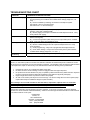
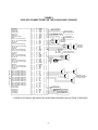
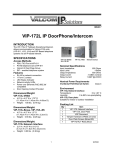
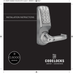
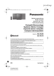
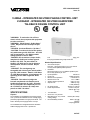
VSP-V-2006A/2006AHF Issue 10 V-2006A - INTEGRATED SIX ZONE PAGING CONTROL UNIT V-2006AHF - INTEGRATED SIX ZONE HANDSFREE TALKBACK PAGING CONTROL UNIT "WARNING: To reduce the risk of fire or electric shock, do not expose this equipment to rain or moisture." "WARNING: Shock Hazard - Do Not Open." "AVIS: Risque de Choc Electrique ne pas Ouvrir." "PELIGRO: Corriente Electrica - No Abra." “CAUTION: To reduce the risk of fire replace only with same type 2A, 125V fuse. 2A, 125V may be replaced by a 1A, 250V provided voltage selector is set for 230V.” “DANGER: Afin de réduire le risque de feu, remplacez le fusible par le même type de fusible à 2A, 125V. On peut utiliser un fusible à 1A, 250V pourvu que le sélecteur ďalimentation soit fixé sur 230V. Ne pas ouvrir.” “VORSICHT: Zur verringerung von feuergefahr die sicherung nur mit derselben type 2A, 125V ersetzen. Statt 2A, 125V Kann 1A, 250V Benutzt werden, vorausgesetzt, die spannung ist auf 230V eingestellt. Nicht öffnen.” “PELIGRO: Para reducir el peligro de incendio remplazarlo unicamente con un fusible del mismo tipo 2A, 125V. El fusible de 2A, 125V podra ser remplazado por uno de 1A, 250V si el selector de voltaje esta puesto en 230V. No abres.” individual zones of talkback and/or one-way paging, plus three programmable zone groups and all call. Nominal Specifications SPECIFICATIONS Purpose The V-2006A is an Integrated Six Zone Paging Control Unit. It provides six individual zones of one-way paging, plus three programmable zone groups and all call. The built-in -24VDC power supply provides 1.5 Amps. Zone Audio Outputs: One-Way: Will supply audio for up to 150 Valcom one-way self-amplified speakers per Zone Handsfree: Will supply audio for up to 2 Talkback Speakers plus 40 one-way speakers per zone Input Impedance: 600 Ohms Input Level: -10dBm minimum Music Source Impedance: 8 to 600 Ohms Music Source Level: -10 to -18dBm Speaker Output Impedance: 8 Ohm (1 way) Output Level: -10dBm (1 way) 1 Watt (talkback) DC Power Output: -24VDC at 1.5 Amps Power Requirements: 115VAC 2 Amps or 230VAC @ 1 Amp (slo-blo) Tone Activation: Clock Tone – Dry Contact Night Ring Tone – Dry Contact -90VAC (20 to 30Hz) or Ring Voltage K5 and K6 Relay Contacts: Rated 1 Amp @ 125VAC 2 Amps @ 30VDC The V-2006AHF is an Integrated Six Zone Handsfree Talkback Paging Control Unit. It provides six 1 947207 Access Methods Features of the V-2006AHF Electronic Key System (C. O. Line Position) PABX (Loop or Ground Start Trunk) 1A2 Key Systems (400 Type Line Card required) 600 Ohms Page port equipped with contact closure and DTMF dialing capability Dedicated single line telephone Additional Equipment Required Backboard/mounting surface 25 pair cable with female connector on one end One 66 split block Speakers Cat 3 or Cat 5 twisted 2-pair cable (for speaker connections) SYSTEM OPERATION DO NOT OPERATE UNIT WITH COVER REMOVED! Physical Description The V-2006A and V-2006AHF are contained in single, gray steel cases, which can be wall or shelf-mounted. V-2006A: V-2006AHF 10.90"H x 13.00"W x 2.70"D (27.69cm H x 33.02cm W x 6.86cm D) 6.2 lbs. (2.81 kg) 10.90"H x 13.00"W x 2.70"D (27.69cm H x 33.02cm W x 6.86cm D) 7.5 lbs. (3.40 kg) +32 to +104° F 0 to +40° C 0 to 85% non-precipitating Environment Temperature: Humidity: Features of the V-2006A 6 zones of handsfree talkback (one-way or mixed) paging (one handsfree output per zone) Two volume controls for handsfree paging Page (Phone to Speaker) Receive (Speaker to Phone) Tone options (dip-switch selectable on a system basis): 1 - dial tone 2 - alert tone (ringback tone) 3 - repeated alert tone Time Clock & Night Ring Tones (single/warble) Override Input (Trunk Port Access) Two Auxiliary Contact Closures Programmable per Zone - Background Music - Clock (single tone) - Night Ring (warble tone) - Group Calls - All Call - One-way/Talkback (V-2006AHF for Talkback) Three group calls and one all call group Volume Controls for: - Background Music (music mutes during page) - Clock and Night Ring Tones - All Call Switch selectable - Dial Tone - Ringback Tone - Loop or Ground Start Battery Backup Input (for VPB-260 only) Inhibit Option for “Meet Me” answer Common all call link for up to (10) V-2006A/ V-2006AHF units To Access Paging/Override: Press CO line key, dial trunk access code or access page port if applicable System Dial Tone: If so optioned (dip switch #1), the V-2006A/V-2006AHF returns dial tone Dialing Zones: Dial 1 to 6 for individual zones Dialing All Call: Dial 0 for All Call Dialing Groups: For Groups 1, 2 or 3 – dial 7, 8 or 9 respectively Activating Make or Break Contact Closures; K5: After dialing any individual zone, press the asterisk (*) once for 2.2 seconds of relay closure K6: This closure activates as long as zone 6 is active Dialing Another Zone: Press pound (#) key to return dial tone Priority Sequence 1) Time Clock Tone 2) Override Page 3) All Call Link 4) Page 5) Warble Tone 6) Background Music Background Music Background music may be connected to control unit. Background music will mute in zone paged if the zone is programmed for background music. Page Override Requires use of a second vacant C. O. line position or vacant loop or ground start trunk port for access. OPERATION: Press line key (electronic key system) or dial trunk access code (PABX) for override access (override busy tone will be heard). Dial zone and make announcement. The unit will disconnect when you hang up, re-establishing the overridden page. 2 Inhibit Option (Meet Me Answer) screws are included for mounting. The V-2006A/V-2006AHF is equipped with an inhibit feature that automatically mutes output to the speakers and allows a handset conversation between the paging party and a single line telephone connected to the paging Tip and Ring. A single line telephone modified for "A" Lead Control and a 5.1K Ohm 1/4 Watt resistor is required to use the inhibit function. NOTE: If the inhibit option has been connected to a single line phone and that phone goes off hook during a page, the speakers will mute. NOTE: All controls and terminations are accessed by removing the small right side panel. To remove panel, loosen the two screws holding the panel in place and lift panel away from the board. SWITCH SELECTABLE OPTIONS Refer to Figure 2. Loop/Ground Start Access If the V-2006A/V-2006AHF is being used with Loop/Ground Start Access, set SW6 to Up (ON). SW2 selects loop or ground start access from the telephone system. SW1 selects loop or ground start access for the override feature. NOTE: When using a ground start trunk port, a ground strap must be used to connect GND of the V-2006A or V-2006AHF to an appropriate telephone system ground (see Figure 1). Inhibit does not affect the override feature. Warble and Single Tones Warble tone is activated when a common audible contact closure or 90VAC ring voltage is supplied by the telephone system to UNA closure or UNA ring input. A single tone may be activated by an additional contact closure to the clock tone input. Page Port Access Group Call If the V-2006A/V-2006AHF is being used with a page port, set SW6 Battery Feed to OFF (down position). Page port must: 1. Provide dry page enable contact closure 2. Pass DTMF tones for zone selection 3. Pass audio in both directions when used with V-2006AHF for handsfree talkback Each group can be programmed with any combination of zones. Zone may be included in multiple groups. Dial codes for group call are 7, 8 and 9. Group calls are one-way only. All Call Group Each zone, 1 through 6, can be programmed for all call (group 0). When "0" is dialed, all zones activate including group 0 of any expansion unit. Dial Tone, Alert Tone/Ringback Tone There are four (4) dip-switches for setting options also located on the board (see Figure 2 also). SW3 Dip Off (UP) ON (DOWN) Switch (away from (toward Options Board) Board) 4 Not Used Not Used 3* Repeated Alert No Repeated Tone Alert Tone 2* Alert Tone/ No Alert Tone Ringback Tone 1 Dial Tone No Dial Tone Page Port Access Page Port requires a 600 Ohm page port that will pass DTMF for zone selection and is equipped with a separate "page enable" contact closure. Additionally, the page port must be capable of passing bi-directional audio if talkback is used. Expansion Unit Up to ten V-2006A/V-2006AHF units can be connected together to provide a system wide all call. Modular RJ11 plugs J7 and J9 are provided for this expansion setup. NOTE: * Alert Tone and Repeated Alert Tone are available only on V-2006AHF handsfree outputs. INSTALLATION Telephone System Access Connections NOTE: The telephone system referred to in this document is the customer premise equipment such as a key system or PABX. The V-2006A/V-2006AHF CANNOT be connected directly to the public telephone network (a central office line). All connections must be made prior to plugging the unit to AC power. A 66 block with 50-pin female amphenol connector is required. See Figure 1 for 66 block pinouts. Tip and ring connections can be made to the RJ11 (J4) with a modular cord or punched down on the W/BL pair on the block. Page Port Connections Mounting Make certain Battery Feed switch is OFF. SW6 should be in Down position. Connect Tip, Ring of Page Port The V-2006A/V-2006AHF was designed for wall or table mounting. Secure unit to wall studs or suitable brace away from heat sources or strong magnetic to W/BL, BL/W. Connect wiring from telephone system’s dry contact closure to W/BR and O/W of the 66 block. fields (motors, fans, power supplies, etc.) with control and terminal strip accessible. Four wood 3 Connection of One-Way Amplified Speakers on that zone. NOTE: Only talkback speakers are able to receive reply. No more than two (2) 45-Ohm talkback speakers should be connected to any talkback zone. Do not use 8 Ohm speakers. See Figure 1, 66 Block Diagram. NOTE: The V-2006A/V-2006AHF provides external power of 30 power units (1.5 Amps of -24VDC) to operate amplified speaker assemblies. Additional power supplies are required for speakers using power over the 30 power units. When using additional power supplies, make certain: Connection of Talkback Speakers (V-2006AHF only) See Figure 1, 66 Block Diagram. 1) 2) 3) The -24VDC outputs are not connected to each other. Each speaker is connected to only one power source (talkback speakers do not require power). All power supply grounds are connected to a copper cold water pipe earth ground. The use of an electrical ground in place of a direct cold water pipe ground may introduce noise into the paging system. OPTIONAL CONNECTIONS Background Music Connections Connect the low level (-10 to -18dBm, 8 to 600 Ohms) output of music source the (W/G) and (G/W) terminals of the cross connect block. Adjust music volume (page overrides music). NOTE: Failure to use a low level music source could cause music crosstalk on zones not receiving music and may override the mute of music during page. Power Connections The V-2006A/V-2006AHF is provided with a NEMA 5-15 cord set. Time Clock Closure (Single Tone) Connections V-2006A Volume Adjustments Time clock contact closure connects to - V/G, G/V. Time clock signaling will override page. There are three volume controls on the unit for individual adjustment of: • Background Music • Tones • All Call Clockwise adjustment increases volume, counterclockwise decreases volume. NOTE: During initial set up, adjust individual speaker volume controls to page level first, then adjust volume on page unit to the desired level for music and tones. UNA Closure Connections Telephone System Night Answer contact closure connects to - V/BR, BR/V. This tone will override music but is overridden by a page. UNA Ringing Connections 90V Night Answer Ring connects to - V/S, S/V. These connections will activate a night ring tone. Telephone System standard ring voltage. This tone will override music but is overridden by page. V-2006AHF Volume Adjustments Override Connections There are six volume controls on the V-2006AHF to control the volume of the handsfree talkback outputs. They are: Page override can be activated by a vacant C. O. line position, loop start or ground start trunk or dedicated single line phone. Connect telephone system override via a telephone modular cord to override RJ11 jack (J5) or Tip, Ring to the W/O, O/W terminals of the cross connect 66 block. Phone to Speaker (adjusts volume of a page from phone) Speaker to Phone (adjusts response volume from speaker; should be turned as low as possible) Page (adjusts volume Group Call on handsfree outputs) All Call Background Music Tones Refer to Figure 2 for location of the volume controls. Remote Door Unlock with Tone Dial Telephone – K5 Relay See Figure 2. Before connecting an electric strikeplate to the V-2006A/V-2006AHF, consult the manufacturer's instruction for the proper installation arrangement. The dry contact closure is operated by pressing the asterisk (*) key on a tone dial telephone after a zone has been accessed. The contact is rated at 1A @ 125VAC or 2A @ 30VDC. Connections for the V-2006AHF The V-2006AHF is programmable on a per zone basis for one-way or talkback communication. A single talkback zone may have both one-way and talkback speakers. One-way amplified speakers may be connected to the handsfree output of a zone programmed for talkback to augment the page output 4 Zone 6 Auxiliary – K6 Relay Connect cord set to unit via IEC 320 female connector located on one end of cord set to IEC 320 male appliance coupler located on the V-2006A. For 115 VAC use, verify fuse rating of 2 Amp and voltage selector switch displays 115VAC. For 230 VAC use, verify the fuse rating of 1 Amp and voltage selector switch displays 230VAC. After all required connections have been made, plug the cord set into appropriate AC wall outlet. The V-2006A/V-2006AHF contains an auxiliary set of make/break contacts which can be used to operate mute contacts on a high powered amplifier or other peripheral devices. Zone 6 dry contact closure operates when Zone 6 is activated alone or in together with a group call or all call. The contacts are rated at 1A @ 125 VAC or 2A @ 30VDC. PRECAUTIONARY DESIGNATIONS TECHNICAL ASSISTANCE Assistance in troubleshooting is available from the factory. When calling, you should have a multimeter, several clip leads, a spare telephone test set available and call from the job site. Call (540) 563-2000 and press 1 for Technical Support or visit our website at http://www.valcom.com. CAUTION RISK OF ELECTRIC SHOCK DO NOT OPEN CAUTION: To reduce the risk of electric shock, Do not remove cover. No user serviceable parts inside. Refer servicing to qualified service personnel. The V-2006A contains no user serviceable parts and is not field repairable. A service facility is maintained in Roanoke, VA. Should repairs be necessary, attach a tag to the unit clearly stating your company name, address, phone number, contact person and the nature of the problem. Send the unit to: This symbol indicates that dangerous voltage constituting a risk of electric shock is present within this unit. Valcom, Inc. Repair and Return Dept. 5614 Hollins Road Roanoke, VA 24019-5056 This symbol indicates that there are important operating and maintenance instructions in the literature accompanying this unit. 5 PROGRAMMING FEATURE CHART LED FEATURES D1 D2 D3 D4 D5 D6 D7 D8 Handsfree (with V-2006AHF only) Background Music Night Ring Clock Tones Included in Group #1 Included in Group #2 Included in Group #3 Included in All Call ZONES 1 PROGRAM EXAMPLE* 2 3 4 5 6 6 0 1 1 1 0 0 0 1 To Program Each Zone Press: # Dial: Zone Number Enter: “1” to Enable Or “0” to Disable For each of the 8 features PROGRAM EXAMPLE: Zone 6 Programmed for One-Way Paging, Background Music, Night Ring, Clock Tones, Not in Group 1-2 or 3 and All Call. PROGRAMMING INSTRUCTIONS System programming is non-volatile and is not affected by power outages. 1. Complete Programming Feature Chart. 2. Connect a single line tone dial phone or butt set to the RJ11 jack J6 (Program Jack). 3. Go OFF HOOK, all LEDs illuminate for 1 second and then extinguish. Program tone will be heard. 4. Press # key (program tone breaks). 5. Dial the number of the zone to be programmed. Program ready tone (3 short bursts will be heard and the first LED will flash). 6. Enter “1” to Enable or “0” to Disable each of 8 features listed in chart above. As each entry is made, the next LED will begin flashing. PROGRAM TESTING INSTRUCTIONS 1. 2. 3. 4. 5. 6. Connect a single line tone dial phone or butt set to the RJ11 jack J6 (Program Jack). Go OFF HOOK, all LEDs illuminate for 1 second and then extinguish. Program tone will be heard. Press * key (program tone breaks). Dial the number of the zone to be checked. Illuminated LEDs represent enabled features. LEDs extinguish after 5 seconds and program tone returns. Repeat the procedure for each zone. NOTES: 1. 2. 3. 4. 5. If the telephone is unplugged from the program jack while programming a zone, the existing program for that zone will not be affected. The control unit cannot be used for paging while a telephone is plugged into the program jack and receiving the "PROGRAM TONE." If numbers other than 1-6 are dialed after dialing "#" or "*", a re-order tone will be heard. Programming must be initiated again, starting with going off hook. If numbers other than "1" or "0" are dialed after dialing "#" and a valid zone number, the re-order tone will be heard. Programming must be started over beginning with going off hook. Tone Definitions: Program Tone/Dial Tone-Continuous Tone - (20Hz, square wave). Program Ready Tone/Override Busy Tone - Three short bursts of tone; 1/4 second on, 1/4 second off (40 Hz, square wave). Re-Order Tone - Interrupted tone; 1/2 second on, 1/2 second off (400Hz, square wave). 6 TROUBLESHOOTING CHART SYMPTOM Cannot Access Paging Cannot Access Zone No Speaker Output No Background Music Programmed Feature Not Working PROBABLE CAUSE AND SOLUTION A) Check V-2006A switch settings. Verify that the phone system connections and programming are consistent with V-2006A switch settings (Page Port, C.O. Port). B) Remove V-2006A Tip and Ring connections from telephone system. Set switches 1 & 2 for Loop Start (down). Set switch 6 for C. O. Port Access (up). A) Monitor access port from phone system (telephone test set in monitor position). Verify port is passing DTMF. B) Monitor paging zone output on V-2006A block with telephone test set. Verify audio present when paging. A) Check AC power source and AC line fuse on V-2006A (disconnect power before removing fuse). B) Connect tone generator (cable tracer) to zone output audio pair on V-2006A block. Verify tone plays over speakers or horns. A) Adjust music volume control (adjustment POT R6). B) Monitor V-2006A background music input with telephone test set. Verify music is present. C) Check programming. Verify zone is programmed for background music. D) Check switch settings. Verify access method from phone system matches V-2006A switch settings (Page Port, C. O. Port …). A) Check V-2006A programming for that option. Re-program zone as necessary. VALCOM LIMITED WARRANTY Valcom, Inc. warrants its products to be free from defects in materials and workmanship under conditions of normal use and service for a period of one year from the date of shipment. The obligation under this warranty shall be limited to the replacement, repair or refund of any such defective device within the warranty period, provided that: 1. 2. 3. 4. 5. inspection by Valcom, Inc. indicates the validity of the claim; the defect is not the result of damage, misuse or negligence after the original shipment; the product has not been altered in any way or repaired by others and that factory sealed units are unopened (a service charge plus parts and labor will be applied to units defaced or physically damaged); freight charges for the return of products to Valcom are prepaid; all units 'out of warranty' are subject to a service charge. The service charge will cover minor repairs (major repairs will be subject to additional charges for parts and labor). This warranty is in lieu of and excludes all other warranties, expressed or implied, and in no event shall Valcom, Inc. be liable for any anticipated profits, consequential damages, loss of time or other losses incurred by the buyer in connection with the purchase, operation or use of the product. This warranty specifically excludes damage incurred in shipment. In the event a product is received in damaged condition, the carrier should be notified immediately. Claims for such damage should be filed with the carrier involved in accordance with the F.O.B. point. Headquarters : Valcom, Inc. 5614 Hollins Road Roanoke, VA 24019-5056 Phone: (540) 563-2000 FAX: (540) 362-9800 7 Used only with the V-2006AHF FIGURE 1 66 BLOCK CONNECTIONS FOR THE V-2006A AND V-2006AHF System Tip System Ring Override Tip Override Ring Music Input Music Input Page Port Access CC Inhibit Zone 1-Low Level Output Tip Zone 1-Low Level Output Ring -24 Volt Out GND Out Zone 2-Low Level Output Tip Zone 2-Low Level Output Ring -24 Volt Out GND Out Zone 3-Low Level Output Tip Zone 3-Low Level Output Ring -24 Volt Out GND Out Zone 4-Low Level Output Tip Zone 4-Low Level Output Ring -24 Volt Out GND Out Zone 5-Low Level Output Tip Zone 5-Low Level Output Ring -24 Volt Out GND Out Zone 6-Low Level Output Tip Zone 6-Low Level Output Ring -24 Volt Out GND Out Zone 1-Handsfree Output Tip Zone 1-Handsfree Output Ring Zone 2-Handsfree Output Tip Zone 2-Handsfree Output Ring Zone 3-Handsfree Output Tip Zone 3-Handsfree Output Ring Zone 4-Handsfree Output Tip Zone 4-Handsfree Output Ring Zone 5-Handsfree Output Tip Zone 5-Handsfree Output Ring Zone 6-Handsfree Output Tip Zone 6-Handsfree Output Ring Clock Closure Clock Closure UNA Closure UNA Closure UNA Ringing UNA Ringing 26 1 27 2 28 3 29 4 30 5 31 6 32 7 33 8 34 9 35 10 36 11 37 12 38 13 39 14 40 15 41 16 42 17 43 18 44 19 45 20 46 21 47 22 48 23 49 24 50 25 WH/BL BL/WH WH/O O/WH W/GR GR/W W/BR BR/W W/S S/W R/BL BL/R R/O O/R R/G G/R R/BR BR/R R/S S/R BK/BL BL/BK BK/O O/BK BK/G G/BK BK/BR BR/BK BK/S S/BK Y/BL BL/Y Y/O O/Y Y/G G/Y Y/BR BR/Y Y/S S/Y V/BL BL/S V/O O/Y V/G G/V V/BR BR/V V/S S/V Loop or GND Start Trunk or Page Port To Loop or Ground Start Trunk Override Low Level Music Input Contact Closure (Page Port) TIP RING -24 VDC GND VALCOM AMPLIFIED SPEAKER TIP RING -24 VDC GND OPTIONAL LOCAL POWER SUPPLY VALCOM AMPLIFIED SPEAKER Appropriate Telephone (Ground strap required System for Ground Start access) Ground TIP RING -24 VDC GND + -24 VDC * VALCOM 45 ohm TALKBACK SPEAKERS (V-2006AHF only) Time Clock Dry Contact Closure Telephone System Common Audible Dry Contact Closure 90 VAC Ringing from an assigned Station Port * POWER SUPPLIES MAY BE ADDED FOR ADDITIONAL SPEAKERS ON ANY ZONE IF REQUIRED 8 FIGURE 2 V-2006A/V-2006AHF Programming Status LEDs D1 - Handsfree or One-Way D2 - Background Music D3 - Night Ring D4 - Time Clock Tone D5 - Group 1 D6 - Group 2 D7 - Group 3 D 8 - All Call Group D1 D2 Phone/Spkr D3 Page 1 SW6 ON UP D6 RJ11's D5 Music Program J6 Tones D7 D8 ON (DOWN) (Toward Board) Not Used No RepeatedAlert Tone Alert Tone/Ringback Tone No Alert Tone Dial Tone No Dial Tone SW1 OFF (UP) (Away from Board) Not Used Repeated Alert Tone DOWN OFF Ground SW2 Ground *2 All Call 1 J9 D4 All Call SW3 DIP SWITCH OPTIONS 4 *3 All Call 2 J7 System J4 Loop 4 3 2 1 Loop SW3 Override J5 R91 Tones Zone 6 Auxiliary (Contact Closure) K6 NC K6 relay operates K6 NO whenever zone 6 Mute is in use K6 COM K6 Relay K5 Relay For Remote Door Unlock K5 relay operates for 2.2 seconds when the * is pressed when any zone accessed K5 NC Break K5 NO Make K5 COM Stationary Common K6 COM Normally Closed Normally Open K6 NO Common R90 K5 NC Normally Open P12 K5 NO J1 MALE AMPHENOL CONNECTOR Fuse AC Connector Battery Backup Molex Connector This side of the V-2006A/V-2006AHF oriented toward floor. Slide Switches SW1 - Ground Start or Loop Start Trunk for Override Feature SW2 - Ground Start or Loop Start Trunk Access SW6 - Battery Feed (ON/OFF) 9 Switch Loop Start Trunk C.O. Ground Start Trunk Page Port All Call K5 COM Normally Closed Customer Provided Electric Strikeplate Solenoid R92 K6 NC SW1 Down SW2 Down SW6 Up Up Up Up --- --- Down Music VOLUME CONTROLS Voltage Select Switch Volume Controls for the V-2006AHF Spkr/Phone