1
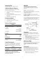
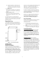
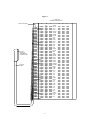
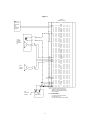
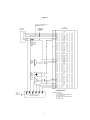
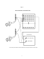
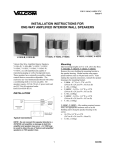
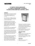
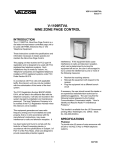
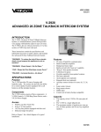
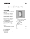
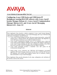
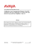
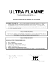
VSP -V-1109RTHF Issue 8 V-1109RTHF NINE ZONE PAGE CONTROL GENERAL The V-1109RTHF, Nine Zone Page Control, is a dial select microprocessor controlled page unit to be used with PABX, Electronic Key or 1A2 Telephone Equipment. These instructions contain the specifications and information necessary to install, operate and maintain the Nine Zone Page Control. This paging unit has received an FCC type KX registration and is designed to be used with FCC registered key telephone systems. In accordance with FCC rules with applicable tariffs, this intercom unit may only be installed with the authorization of the owner of the host system. SPECIFICATIONS Purpose The FCC Registration Number BAFUSA-69358-KX-N will be listed in the affidavits filed with the Telephone Company; it will also be recorded in the system log kept by installation and maintenance personnel. The local Telephone Company is to be notified of the FCC Registration Number when this intercom unit is installed. To provide nine (9) zones of voice announce with handsfree reply paging to 1A2 Key, E-Key or PABX telephone systems. Features This equipment generates and uses radio frequency energy and if not installed and used properly, that is in strict accordance with the manufacturer's instructions, may cause interference to radio and television reception. It has been tested and found to comply with the limits for a Class B computing device, in accordance with the specifications in Subpart J of Part 15 of the FCC Rules, which are designed to provide reasonable protection against interference. If this equipment does cause interference to radio and television reception, which can be determined by turning the equipment off and on, the user is encouraged to try to correct the interference by one or more of the following measures: Reorient receiving antenna Relocate equipment with respect to the receiver Plug equipment into different branch circuit 9 zones Personal signaling (tone only) Dial tone Splash tone Ringback tone 15 second repeat alert tone option Combined rotary and tone dialing Conference calling on tone dial systems (handset to handset) Background music input and amplifier Built-in all call Single digit dialing Off hook speaker inhibit (1A2) Capacity The capacity of the V-1109RTHF is 9 zones and all call One talkpath The maximum number of speakers on a zone are two 45 Ohm Talkback speakers or forty one-way amplified speaker assemblies. . 1 947108 Numbering Plan DESIGN The dialing codes are 1-9 and 0 for all call. Telephone System Requirements Additional Materials Required The V-1109RTHF is designed to work with the following: At the time of installation, the installer should provide the following materials: PABX - Loop start trunk position. ELECTRONIC KEY SYSTEM - C.O. line button equipped with trunk card. -24VDC power supply (if existing supply is not adequate) 66 type connecting block 25 pair cable with a female amphenol connector on one end Twisted pair cross-connect wire 1A2 KEY SYSTEM - C.O. line button on key telephones. NOTE: A 400 type line card is not used for this arrangement. The V-1109RTHF has background music inputs and is capable of switching the music. Refer to the Section titled "Music Connections" for music set up and connections. Dimensions/Weight 7.10" H x 5.90" W x 2.10" D (18.03cm H x 14.99cm W x 5.33cm D) 2.7 lbs. (1.22 kg) Electrical Characteristics Telephone System TABLE 1 Parameters Input impedance Tip and Ring Max cable length to talkback speaker Dial Pulses Tone Signals Frequency Bandwidth Twist Detect Interdigital Time Environmental Temperature Humidity Working Limits 600 Ohms 800 feet audio Valcom V-1109RTHF 1 Talkback Speakers 9 Power Supply 8-12pps 60-40 break ratio +/- 10% Industry Standard Figure 1 Typical Configuration Equipment A complete 9 Zone Handsfree Talkback Paging System using the V-1109RTHF will be made up of the following: PABX loop start trunk position, E-Key C.O. line button or 1A2 line key V-1109RTHF 9 Zone Talkback Control Unit Valcom 45 Ohm Talkback speakers -24VDC power supply (talk and signal battery) 3% 6dB 40ms 40ms 0 to +50°C 0 to 85% Non-precipitating INSTALLATION This section covers the installation procedures for the Valcom V-1109RTHF only. Consult other equipment instructions if additional equipment is used. Power Requirements The Valcom V-1109RTHF requires -24VDC talk battery and -24VDC signal battery. The current consumption and voltage range is shown in Table 2 below. TABLE 2 Talk Battery -21.5 to -26VDC 60mA Signal Battery -21.5 to -25VDC 250mA Lamp Battery 9 to 11VAC 45mA/Lamp Precautions All precautions have been taken at the factory to insure that the equipment functions properly. To insure proper operation and to prevent equipment damage, please observe the following: Remember when working with telephone equipment that BATTERY is NEGATIVE and GROUND is POSITIVE. 2 Unplug the power supply before making any connections to the control unit. Power Connections Do not locate the control unit closer than 18 inches or further than five feet from the power supply. Do not use a lamp tester to check signals, use a voltmeter. A lamp tester when first applies is a short circuit to electronic circuits. Do not apply power to the control unit until all connections have been checked. Mounting The V-1109RTHF is designed to use -24VDC battery Connect the V/BR lead to Talk Ground Connect the BR/V lead to Talk Battery (-24VDC filtered). Connect the V/S lead to Signal Ground Connect the S/V lead to Signal Battery (-24VDC unfiltered) NOTE: When the V-1109RTHF is connected to a 1A2 Key System, connect W/O to 10VAC lamp battery. Refer to Figure 5 for connections. Mount the unit in a vacant space in an equipment cabinet, rack or key system cabinet, allowing enough room at the rear of the unit to plug in an amphenol connector. Mount a 66B type punchdown block near the unit and label it per Figure 2. NOTE: When the V-1109RTHF is connected to a Key System power supply, all grounds should be common and connect to an earth ground, i.e., cold water pipe. Cabling A 25 pair cable with a female connector should be ran from the unit to the connection block. The cable should be terminated on the connection block in standard color code order. Verify that the connections are correct prior to plugging the other end of the cable into the V-1109RTHF Page Unit. Speaker Connections The output for paging zones start at the BK/BR pair (zone 1) through the V/O pair (zone 9). Refer to Figure 4 for typical speaker connections using Valcom 45 Ohm Talkback speakers. No more than two 45 Ohm Talkback speakers may be connected to a zone. Connections to PABX System The V-1109RTHF may be accessed by connecting the W/BL and BL/W to the Tip and Ring, respectively, of a Loop Start Trunk Circuit. Refer to Figure 3 for connections. NOTE: All speakers should be connected with twisted pair, including cross-connections. Music Connections Connections to Electronic Key Systems The output of a tuner or receiver may be connected to the V/G pair of the V-1109RTHF to provide system-wide background music. The V-1109RTHF may be accessed by a C.O. line position of an Electronic Key System by connecting the W/BL, BL/W of the V-1109RTHF to a spare line position of the Electronic Key. This line position must be equipped with a trunk card. Refer to Figure 3 for connections. NOTE: A low level (0.25vrms) 8 to 600 Ohm source should be used. Do not connect the output of a high power amplifier to this input. Page and Music Level Set-up The V-1109RTHF has volume controls for the following functions: Speaker to phone Phone to speaker All Call master control Background music input control Zones 1-5 Background music input control Zones 6-9 Connections to 1A2 Key System The V-1109RTHF may be connected to a spare button of a 1A2 Key Telephone by making the following connections (a 400 type line card is not needed in this application): W/BL, BL/W of V-1109RTHF to spare button Tip and Ring. Refer to Figure 4 for connections. O/W to Lamp Lead of spare button for lamp connections. Refer to Figure 4 for connections. NOTE: For Meet Me Page on 1A2, connect A-Leads from spare button using 10K Ohm resistors in series with each A-Lead. The other side of resistors are connected to the BK/G (inhibit) of V-1109RTHF. Refer to Figure 6 for connections. Refer to Figure 7 for volume control locations. Control Set-Up: 1. Set-up Talkback Controls: (a) The phone to speaker level should be at a normal listening level. 3 (b) Speaker to phone level: This is the most critical level; set the volume at the lowest practical level (it is better to set it too low, than too high). 2. All Call Level: The All call level should be set to produce the same audio level as the phone to speaker page control. 3. Background Music Levels: There are two volume controls provided for background music adjustments: Zones 1-5 and Zones 6-9. turned off. Personal signaling: When initiating a call, depress the "*" and then the station number. A double tone will be sent to the called speaker. No voice announce or talkback will be possible. To dial a new number (tone dial only), depress the "#" button. The speaker for the first number will be disconnected and dial tone returned to calling party. Dial new number and page. NOTE: If "#" is depressed after the speakers have been inhibited, additional numbers may still be dialed. A tone will signal the called party but no voice announce or talkback will be possible. It is important that the two background music controls be used to set the music levels in the system. Adjust these controls after all other system volume levels have been set. User Instructions In order to achieve maximum performance from this system, the user should receive the following operating instructions. Repeat Alert Tone A wire jumper controls the 15 seconds alert tone. The repeat alert tone is disabled when the jumper is in place and is enabled by cutting or removing the jumper. A. B. The calling party should speak directly into telephone mouthpiece and avoid speaking too softly. The called party must wait (approximately 1/2 second) before responding to the calling party. Circuit Description BACKGROUND MUSIC CONTROL ZONES 1-5 General Method of Operation: This unit provides dial intercom access provisions to appropriately interface with the telephone system being used. Two-way amplifier conditions the speech from the telephone system Tip and Ring, and provides a low impedance, low level output to the desired speaker via conventional telephone wiring, i.e., house cable or station wire. BACKGROUND MUSIC CONTROL ZONES 6-9 ONE-WAY ALL CALL VOLUME 50 PIN MALE CONNECTOR Detailed Description: When accessing the V-1109RTHF, the telephone system will close the Tip and Ring to form a loop. Loop sense circuitry then operates relay and logic circuits and returns dial tone and lamp battery to the telephone set. The logic circuit receives dialing information and operates relays and circuitry to supply splash tone and voice connection to the station selected. On 1A2 systems, when the called or any other party goes off-hook on ICM path, the presence of two resistance ground cancels or turns off speakers (if inhibit resistors are wired). "Handsfree mode" can only be restored by terminating call and redialing station. After paging, the unit automatically disconnects on release of the telephone system. SPK-TO-PHONE TURN CLOCKWISE TO INCREASE RECEIVE VOLUME PHONE-TO-SPK TURN CLOCKWISE TO INCREASE TRANSMIT VOLUME Figure 7 - User Control Locations OPERATION General Description To make a voice page, go off-hook and dial the number of the desired zone or station. Dial tone will be broken after the first number is dialed. A one second ringback tone will indicate that the called zone is being signaled. After the tone, proceed with the page. If using talkback speakers, the called party may answer handsfree. If speaker cancel is wired when called party goes off hook, speaker will be 4 Figure 2 V-1109R TH F CO NN EC TIN G BLO C K TYPE 66 BLO C K A B 26 1 27 2 28 3 29 4 30 5 31 6 32 7 33 8 34 9 35 10 36 11 37 12 38 13 39 14 40 15 41 16 42 17 43 18 44 19 45 20 46 21 47 22 48 23 49 24 50 25 T R LB L LG PC S TA1 S TA2 S TA3 S TA4 S TA5 S TA6 S TA7 S TA8 S TA9 50 P IN FE MA LE A M PH EN O L C O N N EC TO R INH 25 PAIR C ABLE R ET S PK1 R ET S PK2 R ET S PK3 R ET S PK4 R ET S PK5 R ET S PK6 R ET S PK7 R ET S PK8 R ET S PK9 MUSIC MUSIC AG AA BG BB 5 C D W /BL BL/W W /O O /W W /G R G R /W W /BR BR /W W /S S/W R/BL BL/R R/O O /R R/G G /R R/BR BR /R R/S S/R BK/B L BL/BK BK/O O /BK BK/G G /BK BK/B R BR /BK BK/S S/BK Y/B L BL/Y Y/O O /Y Y/G G /Y Y/B R BR /Y Y/S S/Y V/BL BL/V V/O O /V V/G G /V V/BR BR /V V/S S/V E F Figure 3 V-1109RTHF CONNECTING BLOCK PABX LOOP START TRUNK PORT OR E-KEY C.O. BUTTON POSITION A T R LED 1 45 OHM TALKBACK SPEAKER W/OPTIONAL LED + LED 9 T R RET SPK1 RET SPK2 45 OHM TALKBACK SPEAKER T R RET SPK9 AG AB BG BB COLD WATER PIPE GROUND B C D E W/BL BL/W W/O O/W W/GR GR/W W/BR BR/W W/S S/W R/BL BL/R R/O O/R R/G G/R R/BR BR/R R/S S/R BK/BL BL/BK BK/O O/BK BK/G G/BK BK/BR BR/BK BK/S S/BK Y/BL BL/Y Y/O O/Y Y/G G/Y Y/BR BR/Y Y/S S/Y V/BL BL/V V/O O/V V/G G/V V/BR BR/V V/S S/V NOTE: IF USING KEY SYSTEM POWER SUPPLY, CONNECT AG, AB, BG, & BB V-1109RTHF TERMINALS TO CORRESPONDING POWER SUPPLY TERMINALS VALCOM VP-624 B POWER SUPPLY ELECTRICAL DEFINITIONS AG: TALK GROUND (+) AB: -24VDC TALK BATTERY (FILTERED) BG: SIGNAL GROUND (+) BB: -24VDC SIGNAL BATTERY (NON FILTERED) 6 F Figure 4 REFER TO FIGURE 6 FR DETAILED CONNECTION OF LAMPS TELEPHONE KEY BUTTON V-1109RTHF CONNECTING BLOCK MULTIPLE TO ALL INTERCOM STATIONS A T R LB L LG TIP RING LAMP LAMP GND A-LEAD LED 1 RESISTOR 10K OHM 5% 1/4 WATT REFER TO FIGURE 4-6 FOR DETAIL CONNECTION OF A-LEADS LED 9 INH 45 OHM TALKBACK SPEAKER NOTE 1 RET SPK1 T R - 45 OHM VALCOM TALKBACK SPEAKER W/ OPTIONAL LED NOTE 1 + RET SPK9 T R AG AB BG BB B C D E F W/BL BL/W W/O O/W W/GR GR/W W/BR BR/W W/S S/W R/BL BL/R R/O O/R R/G G/R R/BR BR/R R/S S/R BK/BL BL/BK BK/O O/BK BK/G G/BK BK/BR BR/BK BK/S S/BK Y/BL BL/Y Y/O O/Y Y/G G/Y Y/BR BR/Y Y/S S/Y V/BL BL/V V/O O/V V/G G/V V/BR BR/V V/S S/V NOTES: 1. NO MORE THAN 2 TALKBACK SPEAKERS PER ZONE COLD WATER PIPE GROUND LG 10VAC AG AB BG ELECTRICAL DEFINITIONS AG: TALK GROUND AB: -24VDC TALK BATTERY (FILTERED) -24VDC BG: SIGNAL GROUND (+) BB: SIGNAL BATTERY (NON FILTERED) -24VDC LB: 10VAC LG: 10VAC GROUND BB KEY SYSTEM POWER SUPPLY 7 Figure 5 BLOCK DIAGRAM OF LAMP CONNECTIONS T T R LS L SPK SPK SPK SPK R A L LG SPK SPK T R A L LG SPK SPK POWER SUPPLY 10VAC LAMP SUPPLY LAMP GROUND Connect lamp ground leads from telephone ICM buttons to lamp ground terminal on power supply. 8 Figure 6 Connect intercom "A" leads to individual rows on left side of split 66 block. Punch down 10K resistors across center of block. Strap individual rows together on right side of block and jumper to inhibit lead of Valcom ICM. BLOCK DIAGRAM OF A-LEAD CONNECTIONS TYPICAL VALCOM INTERCOM BLOCK T T R L R A L SPK SPK SPK SPK SPK SPK INH T R A L SPK SPK A-LEAD BLOCK 66M3-50 A A 10K RESISTORS BLACK BROWN ORANGE GOLD 10K RESISTOR 9 TECHNICAL ASSISTANCE Repair and Return Factory Assistance Valcom equipment is not field repairable. Valcom maintains service facilities in Roanoke, VA. Should repairs be necessary, attach a tag to the unit clearly stating your company name, address, phone number, contact person and the nature of the problem. Send the unit to: Valcom, Inc. Repair and Return Dept. 5614 Hollins Road Roanoke, VA 24019-5056 When trouble is reported, make certain there are no broken connections leading to the system. The chart below identifies possible problems with solutions. Assistance in troubleshooting is available from the factory. When calling, you should have a VOM and a telephone test set available and be calling from the job site. Call (540) 563-2000 and press 1 for Technical Support or visit our website at http://www.valcom.com. TROUBLESHOOTING CHART PROBLEMS No side tone No dial tone No volume to speakers Hum heard at phone No speaker cancel Background music distorted PROBABLE CAUSES AND CORRECTIONS Check "A" battery connection, polarity and voltage. Check "A" and "B" battery connections, polarity and voltage. Check phone to speaker control. Check * for audio present at tip, ring input (W/BL, BL/W pair). Check * for audio at signaled speaker pair at 66B block. Check * for audio at input of speaker. Possible magnetic interference from power supply. Relocate unit and cables at least 18" away from power supply. Check for noisy "A" battery. Verify twisted pairs are being used for speaker connections. Verify ground present at phone side of at least (2) 10K Ohm resistors. Refer to Figure 6. NOTE: Do not apply ground directly to inhibit input. Music source level too high. Refer to "Music Setup Section". VALCOM LIMITED WARRANTY Valcom, Inc. warrants its products only to the original purchaser, for its own use, to be free from defects in materials and workmanship under conditions of normal use and service for a period of one year from the date of shipment. This Limited Warranty obligation shall be limited to the replacement, repair or refund of any such defective device within the warranty period, provided that: 1. inspection by Valcom, Inc. indicates the validity of the claim; 2. the defect is not the result of damage, misuse or negligence after the original shipment; 3. the product has not been altered in any way or repaired by others and that factory sealed units are unopened (a service charge plus parts and labor will be applied to units defaced or physically damaged); 4. freight charges for the return of products to Valcom are prepaid; 5. all units 'out of warranty' are subject to a service charge. The service charge will cover minor repairs (major repairs will be subject to additional charges for parts and labor). This Limited Warranty is in lieu of and excludes all other warranties, expressed or implied and in no event shall Valcom, Inc. be liable for any anticipated profits, consequential damages, loss of time or other losses incurred by the buyer in connection with the purchase, operation, maintenance, installation, removal or use of the product. The maximum liability of Valcom under this warranty is limited to the purchase price of the specific Product covered by the warranty. Disclaimer. Except for the Limited Warranty provided herein, the product is provided “as-is” without any warranty of any kind whatsoever including, without limitation, any WARRANTY OF MERCHANTABILITY, FITNESS FOR A PARTICULAR PURPOSE OR NON-INFRINGEMENT. This warranty specifically excludes damage incurred in shipment. In the event a product is received in damaged condition, the carrier should be notified immediately. Claims for such damage should be filed with the carrier involved in accordance with the F.O.B. point. Headquarters: Valcom, Inc. 5614 Hollins Road Roanoke, VA 24019-5056 Phone: (540) 563-2000 FAX: (540) 362-9800 10 K0 A GROUND A BATTERY BATTERY FEED TIP K1 MICROPROCESSOR RING K10 K1 RET 1 INHIBIT PAGE CONTROL TONE DECODER TALKBACK AMPLIFIER B GROUND K3 ALL CALL CONTROL K4 POWER SUPPLY SPK 3 RET 4 K0 LED 2 SPK 2 RET 3 K5 1-5 LED 1 SPK 1 RET 2 K10 LAMP SUPPLY LAMP B BATTERY K2 RET 5 AMP K6 6-9 LED CONTROL K0 SPK 5 RET 6 AMP K7 LED 9 SPK 4 SPK 6 RET 7 MUSIC IN MUSIC IN K8 MUSIC CONTROL SPK 7 RET 8 K9 SPK 8 RET 9 SIMPLIFIED SCHEMATIC V-1109RTHF 11 SPK 9