1
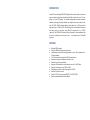
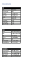
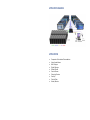
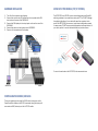
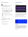
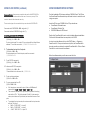
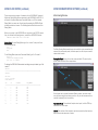
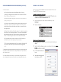
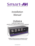
NOTICE The information contained in this document is subject to change without notice. SmartAVI makes no warranty of any kind with regard to this material, including but not limited to, implied warranties of merchantability and fitness for particular purpose. SmartAVI will not be liable for errors contained herein or for incidental or consequential damages in connection with the furnishing, performance or use of this material. DVR16X16 No part of this document may be photocopied, reproduced, or translated into another language without prior written consent from SmartAVI Technologies, Inc. Designed and Manufactured in the USA 800.AVI.2131 Tel: (818) 503-6200 Fax: (818) 503-6208 11651 Vanowen St. North Hollywood, CA 91605 SmartAVI.com Many industry-leading companies have recognized the innovation and power of SmartAVI’s technologies and have successfully implemented them within their systems. Users of SmartAVI technology include: 16-port DVI-D Matrix Switch with Front Panel, RS-232, and TCP/IP Control USER MANUAL WHAT’S IN THE BOX? LIMITED WARRANTY STATEMENT PART NO. QTY. DESCRIPTION DVR16x16S 1 DVI-D 16x16 Router. Includes: [DVR16x16 & CCPWR06USA] User Manual 1 A. TABLE OF CONTENTS INTRODUCTION & FEATURES 3 TECHNICAL SPECIFICATIONS 4 APPLICATIONS 5 HARDWARE INSTALLATION 6 USING THE FRONT PANEL CONTROL 7 USING THE SMARTCONTROL SOFTWARE 9 OPTIONAL CONTROL METHODS 15 USING THE IR REMOTE CONTROL (OPTIONAL) 16 USING RS-232 CONTROL (OPTIONAL) 17 USING THE SMTCP MODULE (OPTIONAL) 23 LIMITED WARRANTY STATEMENT 30 Extent of limited warranty 1. SmartAVI Technologies, Inc. warrants to the end-user customers that the SmartAVI product specified above will be free from defects in materials and workmanship for the duration of 1 year, which duration begins on the date of purchase by the customer. Customer is responsible for maintaining proof of date of purchase. 2. SmartAVI limited warranty covers only those defects which arise as a result of normal use of the product, and do not apply to any: a. Improper or inadequate maintenance or modifications b. Operations outside product specifications c. Mechanical abuse and exposure to severe conditions 3. If SmartAVI receives, during applicable warranty period, a notice of defect, SmatAVI will at its discretion replace or repair defective product . If SmartAVI is unable to replace or repair defective product covered by the SmartAVI warranty within reasonable period of time, SmartAVI shall refund the cost of the product. 4. SmartAVI shall have no obligation to repair, replace or refund unit until customer returns defective product to SmartAVI. 5. Any replacement product could be new or like new, provided that it has functionality at least equal to that of the product being replaced. 6. SmartAVI limited warranty is valid in any country where the covered product is distributed by SmartAVI. B. Limitations of warranty TO THE EXTENT ALLOWED BY LOCAL LAW , NEITHER SMARTAVI NOR ITS THIRD PARTY SUPPLIERS MAKE ANY OTHER WARRANTY OR CONDITION OF ANY KIND WHETHER EXPRESSED OR IMPLIED , WITH RESPECT TO THE SMARTAVI PRODUCT , AND SPECIFICALLY DISCLAIM IMPLIED WARRANTIES OR CONDITIONS OF MERCHANTABILITY, SATISFACTORY QUALITY , AND FITNESS FOR A PARTICULAR PURPOSE C. Limitations of liability To the extent allowed by local law the remedies provided in this warranty statement are the customers sole and exclusive remedies TO THE EXTENT ALLOWED BY LOCAL LAW , EXCEPT FOR THE OBLIGATIONS SPECIFICALLY SET FORTH IN THIS WARRANTY STATEMENT , IN NO EVENT WILL SMARTAVI OR ITS THIRD PARTY SUPPLIERS BE LIABLE FOR DIRECT, INDIRECT, SPECIAL, INCIDENTAL, OR CONSEQUENTIAL DAMAGES WHETHER BASED ON CONTRACT , TORT OR ANY OTHER LEGAL THEORY AND WHETHER ADVISED OF THE POSSIBILITY OF SUCH DAMAGES. D. Local law To the extent that this warranty statement is inconsistent with local law, this warranty statement shall be considered modified to be consistent with such law. INTRODUCTION SmartAVI’s non-blocking DVR16X16 digital video matrix switch provides an easy and dynamic approach to switching the DVI output from up to 16 computers, to up to 16 displays. The matrix configuration provides maximum flexibility, allowing switching between any digital video source and/or display. The DVR 16x16 provides digital video output up to 30 feet and at resolutions up to 1920 x 1200. The switching can be controlled directly via the front panel, or remotely using RS-232 commands, IR, or TCP/IP (optional). The DVR16X16 is controlled by Windows® -based software that is easy to understand and simple to use – a cornerstone of all SmartAVI products. FEATURES Multiple EDID support Supports EDID learning from any display Increases productivity by providing access to up to 16 computers from 16 work stations 16 x 16 non-blocking, single-link DVI-D matrix switch Automatic output pre-emphasis and drive level Automatic receiver equalization Supports DVI operation at the maximum rate of 2 x 1.65 Gbps Supports resolutions up to 1920 x 1200 Switching controlled via the front panel or RS-232 Optional IR remote control Optional TCP/IP control (using SMTCP-2 or NET-IP-PRO) Easy-to-use Windows®-based software TECHNICAL SPECIFICATIONS APPLICATION DIAGRAM APPLICATIONS Corporate or Educational Presentations Airport Installations Wall Displays Digital Signage Dealer Rooms Control Rooms Shopping Centers Security Point-of-Sale Hotels/Resorts HARDWARE INSTALLATION USING NET-IP-PRO MODULE (TCP/IP CONTROL) 1. Turn off all the computers and displays. 2. Connect the male to male DVI cables from the computers to the DVI input ports on the rear of the DVR16x16. 3. Connect the DVI displays to the output ports on the on the rear of the DVR16x16. 4. Connect the power cord and power-on the DVR16X16. 5. Power on the computers and the displays. The NET-IP-PRO is an RS-232 control module that allows most SmartAVI switching matrixes to be controlled remotely via HTTP or TELNET. Manage the switching functions of your matrix with ease from anywhere in the world. With NET-IP-PRO you can save input/output configuration presets for easy access. TELNET access provides transparent command control of your matrix, perfect for use with automated third-party control software. For more information about the NET-IP-PRO, visit www.smartavi.com. CONTROLLING THE HDR8X8/HDR16X16 There are multiple ways to control the DVR: via the front panel, via the SmartControlPro software, via RS-232 commands (using third-party software such as AMX, Crestron), and with a TCP-IP module USING RS-232 CONTROL (continued) USING THE FRONT PANEL CONTROL NOTES: When successful, commands #1-5 will acknowledge by sending the checksum with nibbles swapped & <CR><LF> e.g. checksum of 0x24 acknowledges with <0x42><CR><LF> Front Panel Buttons All bytes in examples are ASCII characters unless they are contained in brackets <> Calculating the Checksum: <CHK> stands for CHECKSUM: the <CHK> value is calculated by performing an XOR of the full command string *For example: //F00M12I03 will XOR to the hexadecimal value 0x42, therefore the value of <CHK> is 0x42 <CHK> is the logical exclusive OR (XOR) of all previous bytes. <CR> is carriage return (0x0D), all commands sent from PC end with <CR>. <LF> is line feed (0x0A) To lock the front panel buttons to avoid any accidental changes, press ESC + MENU + ENTER + SWITCH at the same time. The display will indicate that it is locked. Repeat the procedure to unlock the front panel. During normal operation, you will see a list of ports on the front panel display. xx is the frame address of the router e.g. “00” or “01” From the factory the address is always “00”, however it can be changed with command #5 above. yy is the Output (monitor) number. e.g. “01” zz is the Input number. e.g. “06” or “16” nn is the Matrix’s new frame address Default Display To assign an output to an input, press SWITCH. A blinking block cursor will appear. Use UP and DOWN to select the input that you would like to assign. Once the cursor is over the desired input port, press ENTER to enter editing mode. Press UP and DOWN to select the output port. Once you have selected an output, press ENTER to save the configuration. To escape from editing mode, press ESC. Main Menu To view the menu, press MENU. There are 6 menu options available: USING RS-232 CONTROL (continued) 7. To reboot the processor: //BOOT<CR> 8. To restore the matrix to factory defaults: //RESET<CR> You must cycle matrix’s power after this command. 9. To change data switching mode to RS-232 (user sets data xpoints) //RS<CR> 10. To change data switching mode to IR (data follows last switch to any input) //IR<CR> Manage EDID - Gives the option to learn the EDID of your display or choose a programmed EDID that is compatible with your monitor. RS-232 Acknowledge - Sets the DVR16x16 to send a confirmation that an RS-232 command has been received. Send Update - Sets the DVR16X16 to send an RS-232 command back to the controller when the configuration is changed via the front panel or remote control (optional). Memory Save - Sets the DVR16X16 to save the configuration when powered off. 11. To query version number: //XXXX<CR> B. Sending commands without CHECKSUM: 1. To set a video crosspoint: \\FxxMyyIzz<CR> Ex. to set video input 3 to output 12 on a router with the default frame address “0” send the command: \\F00M12I03<CR> 2. To broadcast an input to all outputs: \\FxxBzz<CR> Ex. to broadcast input 3 to all outputs, send the command: \\F00B04<CR> 3. To set RS-232 crosspoint: \\FxxRyyIzz<CR> Display Input Status - This displays the status of the inputs. If no input is present, the display will read NONE. This is the default view. 4.To disconnect RS-232 crosspoint: \\FxxDyyIzz<CR> *A new method is to disconnect all: //F00D<CR> Restore Factory Settings - Sets the DVR16x16 to the default factory configuration. 5. To set new frame address: \\FxxFnn<CR> 6. To query crosspoints from PC: \\FxxU<CR> USING RS-232 CONTROL (continued) USING THE SMARTCONTROL SOFTWARE Command Mode: allows raw commands to be sent to the DVR 16x16 to control its various functions without the use of a menu or prompt. This mode is intended for advanced use only. Find the Installation CD that came with your DVR16x16 unit. This CD has the SmartControlPro software that you will need in order to control the unit using a computer. There are two types of commands that you can issue the DVR 16x16: Insert the CD into your CD-ROM. On the CD you should see: SmartControl Pro Installer.exe SmartControl Pro Help File DVR16X16 Manual in PDF format Commands with CHECKSUM <CHK> begin with // Commands without CHECKSUM begin with \\ A. Sending commands with CHECKSUM: 1. To set a video crosspoint: //FxxMyyIzz<CHK><CR> Ex. to set video input 3 to output 12 on a router with the default frame address “0” send the command: //F00M12I03<0x42><CR> 2. To broadcast an input to all outputs: //FxxBzz<CHK><CR> Ex. to broadcast input 3 to all outputs, send the command: //F00B0402<CR> 3. To set RS-232 crosspoint: //FxxRyyIzz<CHK><CR> 4.To disconnect RS-232 crosspoint: //FxxDyyIzz<CHK><CR> *A new method is to disconnect all: //F00D<CR> 5. To set new frame address: //FxxFnn<CHK><CR> 6. To query crosspoints from PC: //FxxU<CHK><CR> If all outputs are connected to input 1 then a 4x4 Matrix will respond with <0x80><0x80><0x80><0x80><CR> The router will send back one byte for each output and the string ends with a <CR>. The first byte sent is Out#1. In the example above, since there are 5 bytes total, we know that there are 4 outputs. To calculate the input number, the router sends the input number with the 7th bit set. o 0x80 = “1000 0000” >> input 0 o 0x81 = “1000 0001” >> input 1 o …0x8F “1000 1111” >> input 15 Double click SmartControlPro.exe in order to initiate software installation. Click Install. After installation has completed, click CLOSE. In order to use the software, click on the START button > Programs > SmartControlPro. There you should see a help file, the SmartControlPro launcher as well as a shortcut to uninstall SmartControlPro. Click on SmartControlPro in order to launch the software. When the software starts you will see a screen like this: USING THE SMARTCONTROL SOFTWARE (continued) USING RS-232 CONTROL (continued) Router Count: Set to the number of routers connected to the computer. To display the help menu for a list of commands, type “? <enter>” Advanced Configuration: This option is used when there is more than one router being used or when all the inputs are not looped from router to router. For most applications, this box is usually unchecked. Reset Advanced Configuration: Returns the advanced setting to their default settings. Router Type: Select the type of router that is connected to the computer. Inputs: Enter the number of physical inputs on the back of the router. Outputs: Enter the number of physical outputs on the back of the router. Note: Inputs and outputs are automatically configured when the router type is chosen. These parameters are changed when router type is not available on the list. COM Port: Choose the correct com port number that connects to the router. Router Timeout: Set how many seconds the program will wait for the router to respond to commands. The default is 0.2 seconds. Comm Type: This option is set automatically when the router type is selected. When finish with the settings, click OK. This will take you to the Main Routing Window. DBG>? ========================================================= Command Line Interface Help: d sw br om o q Enable/Disable debug Switch Port Broadcast Port Set output mode Enable/Disable Output Query Crosspoints d [on][off] sw [output] 1-16 [input] 1-16 br [input] 1-16 om [output] [mode# (0-2) | ?] o [output] [0 = disable | 1 = enable h reset Toggle Hotplug Restore Factory Settings h boot Reboot matrix info Display matrix info edid Manage EDID help Command list [input] ? To switch ports, type “sw [output] 1-16[input] 1-16 <enter>”: DBG>sw 2 2 Switched Output 2 to Input 2 To set the broadcast port, type “br [input] 1-8<enter>”: DBG>br 2 To manage the EDID modes, type “edid <enter>” and you will see the following prompt: DBG>edid EDID Mode: EDID> To learn the EDID, type “learn <enter>”: EDID>learn Successfully learned EDID! To set the EDID to factory default 1920x1080, type “PC-1080 <enter>”: EDID>PC-1080 Successfully learned EDID! To set the EDID to factory defaults, type “PC-1200 <enter>”: EDID>PC-1200 Successfully learned EDID! USING RS-232 CONTROL (continued) USING THE SMARTCONTROL SOFTWARE (continued) There are two primary modes of operation for the DVR16x16: Command Mode and Debug Mode. When connecting to the DVR16x16 via RS-232, it will start in Command Mode (see Command Mode on p. 19 for options). Debug Mode is a more user- friendly way of operating the DVR16x16 and includes instructional menus. The following section details the use of the Debug Mode. Main Routing Window When you connect to the DVR16X16 to a computer via an RS-232 connection, you will see the following screen (results from HDR16X16 shown): SmartAVI DVR 16X16 ver 12.06.11#1 Debug Mode: To enter Debug Mode type “d on <enter>” and you will see the following prompt: d on Debug mode: DBG> To exit Debug Mode (and enter Command Mode) type “d off <enter>”: DBG>d off Command line debugging disabled. Type “d on” to re-enable. The Main Routing Window enables you to control the router connections by means of the cross-point panel, the button panel, or with the pre-recorded routes called macros. Cross-point Panel: Simply click on the cross point itself. The input on the left will then be routed to the output above. To display the DVR 16x16 information including cross-point data, type “info <enter>”: DBG>info ==================================================================== SmartAVI DVR 16X16 fw ver. 12.06.11#1 Frame Address: 0 OUT IN IN STATE OUT_ENABLED ==================================================================== 1 1 DVI YES 2 1 DVI YES 3 1 DVI YES 4 1 DVI YES 5 1 DVI YES 6 1 DVI YES 7 1 DVI YES 8 1 DVI YES ... 16 1 DVI YES Note: Inputs can be routed to several different outputs, but each output can only have a single input at any one time. So you can have several connections horizontally but not vertically. The Button Panel: To broadcast all outputs to an input, hold the CTRL key down and click on an input. Macros: This section of the window is used to save and play black macros. Macros store a set sequence of routes. USING THE SMARTCONTROLPRO SOFTWARE (continued) USING RS-232 CONTROL To record a macro: How to properly create an RS-232 connection between a PC and most SmartAVI RS-232 compliant devices. a. Click on the Record button. Select Manual Save. A blinking “Recording” message below this button will be displayed to indicate that all routes are being recorded. b. Select the desired cross-points. There is no limit on the number of routes you may record. c. If you click a macro button while in the record mode, the macro will be executed, and these routes will be added to the recording. This makes it possible to combine the routes of two or more macros into one bigger macro. Establish a connection to DVR16x16: 1. Connect a straight through male-to-female RS-232 cable (not included) to the RS-232 connector on the PC. 2. Connect the other end of the cable to the RS-232 port of the DVR16x16. 3. Power on the device. d. When finished, click the Save Macro button. You will be instructed to then click on one of the macro buttons. Then, you will be prompted to write a name for this button. This will save the recorded routes to that button. To cancel saving the macro, click the Cancel Save button. e. To play back a macro, simply click on one of the 50 macro but tons.Use the scroll bar to bring any of these into view. f. The macros are automatically saved in the current configuration file. They are also saved when you select the File>Save Configuration menu. Setting up the Terminal Application: 1. Open Hyperterminal on the PC. (or use the terminal client of your choice) 2. Use the default settings to create a connection to the device: 9600, 8, N, 1.(see settings on right). To change the input and output names, simply click on the box next to the input/output number (located under the Input Names or Output Names) and change the text. 3. Be sure that Flow Control is None. The Update Matrix button allows you to update the configuration on the main routing window based on the actual current settings on the router. 4. The output of the device will be the same as the PC.