1
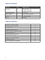
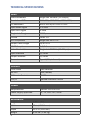
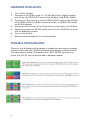
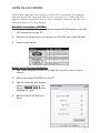
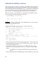
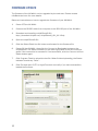
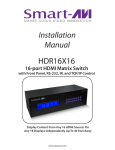
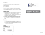
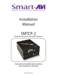
4K-WALL
HDMI/DVI 2x2 Video Wall Controller and
4x4 Matrix Switch
The ideal video wall controller and video matrix hardware solution with
On Screen Display and stunning 4K resolution, no software required
USER MANUAL
WHAT’S IN THE BOX?
PART NO.
QTY.
DESCRIPTION
SM-4KWL-S
1
4X4 Port HDMI, Real-Time Matrix with
integrated video wall
Includes: [SM-4KWL]
Power supply cord
1
(CCPWR06)
RS-232 Cable
1
RS-232 (male-to-female)
SRC-2A
1
IR Remote Control
SM-EYE
1
IR receiver
TABLE OF CONTENTS
INTRODUCTION & FEATURES
3
TECHNICAL SPECIFICATIONS
4
APPLICATIONS
5
HARDWARE INSTALLATION
6
USING THE FRONT PANEL CONTROL
7
ON-SCREEN DISPLAY
8
USING IR REMOTE CONTROL
8
USING RS-232 CONTROL
9
USING THE TCP/IP CONTROL
11
FIRMWARE UPDATE
12
LIMITED WARRANTY STATEMENT
14
2
INTRODUCTION
To create a four-screen video wall with four HD video inputs, the 4K-Wall
video wall controller and matrix provides a truly simple plug-and-play hardware solution with incredible 4K resolution. With four inputs and four outputs, users can arrange their content in numerous ways, providing unique
functionality by combining the abilities of a video wall hardware controller
and a matrix. The 4K-Wall is HDCP compliant.
Users can stretch one large image over four screens, send an input to each
screen, send four images to each screen or create a customizable Picturein-Picture display. Better still, there’s no software required, as all content
management options are effortlessly controlled via the 4K-Wall video wall
controller unit itself. There’s no need for drivers or updates, just connect
the HD inputs and HD screens to the controller and it’s ready to go.
FEATURES
•
•
•
•
•
•
•
•
•
•
•
Stand-Alone Unit, Requiring no Additional Hardware or Software
Plug-and-play ready
Four HDMI inputs and four HDMI outputs
DVI-D up to 1920x1200 input
Learns any EDID
Internal EDID database
Multiple configurations
Easy control and access
HDCP and HDMI 1.4 compliant
Supports IR and RS-232
4K2K/3840x2160 total (with 1920x1080 monitors)
3
TECHNICAL SPECIFICATIONS
VIDEO
Video Bandwidth
Single-link 340MHz [10.2Gbps]
Resolution HDTV
480i,480p,720i,720p,1080i,1080p
PC Resolution
800 x 600 up to 1920 x 1200
Input Video Signal
1.2 volts
Input DDC Signal
5 volts
Single Link Range
1080p
Format
HDMI 1.4
DVI Compliance
Single-link DVI-D 2.0
Output Cable Length
Up to 20 ft.
HDCP Compliance
1.0/2.0
Video Bandwidth
Single-link 340MHz [10.2Gbps]
Input Interface
(4) HDMI
Output Interface
(4) HDMI
Connector
Type A [19-pin female]
CONTROL
Front Panel
Tact Switches
RS-232
DB9 (female)
IR Remote Control
IR RC5
TCP/IP
Optional Ethernet Control
POWER
Requirements
Internal 100-240 VAC
Power Supply Approvals
UL, CE, CSA, CEC, RoHS
MECHANICAL
Height
1.70 in. (1U)
Width
17 in. (431.8 mm.)
Depth
10.2 in. (259 mm.)
Weight
4.05 lbs. (1.84 kg.)
4
APPLICATION DIAGRAM
APPLICATIONS
•
•
•
•
•
•
•
•
•
•
•
•
Corporate or Educational Presentations
Airport Installations
Wall Displays
Digital Signage
Dealer Rooms
Control Rooms
Shopping Centers
Security
Point-of-Sale
Entertainment Venues
Corporate Lobbies
Restaurants
5
HARDWARE INSTALLATION
1. Turn off the 4K-Wall.
2. Connect the (4) HDMI inputs (i.e. PC, Blu-Ray Player, Digital Signage,
etc.) to the (4) HDMI INPUT ports of the 4k-Wall using HDMI cables.
3. Connect the (4) monitors to the (4) HDMI OUTPUT ports of the 4k-Wall
using HDMI cables for HDMI monitors and TVS, or HDMI-to-DVI adapters for DVI displays.
4. Connect the IR receiver to the IR input jack at the back of the 4k-Wall.
5. Optionally connect an RS-232 cable from PC to the RS-232 port of the
unit for additional control.
6. Turn on the 4k-Wall.
7. Wait for a few seconds for the unit to initialize.
AVAILABLE CONFIGURATIONS
There are four different configurations or modes that are easy to navigate
through with the 4k-Wall. Switching between the display modes is simple.
The front panel buttons, IR remote control, OSD, RS-232 console command, and TCP/IP can be used to switch between modes.
6
CONTROL USING THE FRONT PANEL
Front Panel Buttons
•
To switch to Video Wall Mode, press the QUAD and MENU buttons simultaneously and then press the desired channel 1, 2, 3, or 4.
•
To switch to Individual Mode:
1. Press the FULL button on the front control panel
2. Press the Output Channel (1, 2, 3, or 4).
3. Press the Input Channel (1, 2, 3, or 4).
Ex. Input 4 to output 2 = “FULL, 2, 4”
•
To switch to Picture in Picture mode, press the PiP button and then
select the desired channel 1, 2, 3, or 4.
•
To switch to Quad Mode, press the QUAD button and then select the
desired channel 1, 2, 3, or 4.
7
CONTROL USING ON-SCREEN DISPLAY (OSD)
On Screen Display (OSD) gives users great flexibility and ease of use when looking to manage
their video wall. It can be operated with the IR
Remote Control and through the Front Panel
Buttons.
IR REMOTE CONTROL
The 4K-Wall will only respond to the remote
control unit provided in the box. Below is the
list of commands on how to control using the
remote control:
DATA: Activates the OSD
Ch. DOWN: Navigate down through the options
Ch. Up: Navigate up through the options
Vol. +: Select
Vol. -: Back
ENTER: Enter the command
ESC: Exit OSD
OSD CONTROL WITH FRONT PANEL
To change modes with the OSD simply navigate using the following buttons
on the front panel:
1: Down
2: Up
3: Back
4: Select
FULL: Enter
Simply scroll to the mode desired with the up or down button, select the
mode, select the appropriate channel and enter.
8
USING RS-232 CONTROL
The 4K-Wall may also be controlled via RS-232 commands. This feature
requires an RS-232 card installed on your computer or a USB to RS-232
adapter. Below are instructions on how to properly create an RS-232 connection between a PC the 4K-Wall
Establish a connection to 4K4K-Wall:
1. Connect a straight- through male-to-female RS-232 cable to the RS232 connector on the PC.
2. Connect the other end of the cable to the RS-232 port of the 4K-Wall.
3. Power on the device.
Setting up the Terminal Application:
1. Run HyperTerminal on the PC (or use the terminal client of your
choice).
2. Select the correct COM Port on the PC.
3. Use the following settings to
create a connection to the
device: 115200,
115200 8, N, 1.(see
settings on right).
4. Be sure that Flow Control is
None.
9
USING RS-232 CONTROL (continued)
There are two primary modes of operation for 4K-WALL: Command Mode
and CLI Mode. When connecting to the 4K-WALL via RS-232, it will start in
Command Mode (see Command Mode on p. ** for options). CLI Mode is a
more user- friendly way of operating the DVR16x16 and includes instructional menus. The following section details the use of the CLI Mode.
When you connect to the 4K-WALL to a computer via an RS-232 connection, you will see the following screen on startup:
******4KWall v.1.20.1*******
build date Mar 7 2014 10:53:44
…
…
4KWall Initialization complete
CLI Mode: To enter CLI Mode type “clion” followed by the <enter> key and
you will see the following prompt:
CLI enabled!
To display the 4K-WALL help menu type “?” then <enter> key:
4KWall v.1.20.1 CLI command list
=========================================================
i
List system information
f
Full f [Input] [Output]
q
Quad q [USER]
p
PiP p [Main Screen<1-4>]
v
VideoWall
o
Output o [ 1-1080P60 | 2-720P | 3-1080P30 ]
rEDID <1-4> Read a EDID for an input
wEDID <1-4/a> < 1-ACER P241w | 2-Gateway FHX2300 | 3-local monitor>
reset Reset 4K-Wall
losd load osd image
?
CLI command list
• To see the list of inputs and the output mode, type “i” then <enter> key.
• To read the EDID for an input, type in “rEDID N” then <enter>, where “N”
is the input channel (1 to 4).
• To program an EDID to the inputs, type in “wEDID N M” then <enter>,
where “N” is the input channel (1 to 4, or a = all), and “M” is the EDID
mode.
Ex. “wEDID a 3” is to learn the EDID of the local monitor to all
inputs
• To do a power reset on the 4K-Wall, type “reset” followed by <enter> key.
10
USING RS-232 CONTROL (continued)
Command Mode: allows raw commands to be sent to the 4K-WALL to control its various functions without the use of a menu or prompt.
Mode
Console
Command
Video Wall
Mode
//Vx<CR>
Individual
Mode
//Fxy<CR>
Quad Mode
//Qx<CR>
PiP Mode
//Px<CR>
4 inputs on each screen; “x” input is the largest area.
ex. “//P3” Picture in picture mode; input 3 selected
Reset
//RESET<CR>
Resets the 4K-Wall box
Description & Example
Stretch an input across four screens (2x2).
ex. “//V3<CR>” Video wall on channel 3
Route an input to an output on full screen;
x = input, y = output
ex. “//F31” Full mode; input 3 to output 1
4 inputs on each screen, equally displayed.
ex. “//Q2<CR>” quad mode; channel 2 as user control
<CR
CR>
CR is carriage return (0x0D). All commands sent from PC end with <CR>
(or the <enter> key if using HyperTerminal).
TCP/IP CONTROL
4K-WALL TCP/IP control is a feature that allows mode switching and other
configurations to be controlled remotely via HTTP or TELNET. Manage the
switching functions of your matrix with ease from anywhere in the world.
You can save input/output configuration presets for easy access. TELNET
access provides transparent command control of your matrix, perfect for use
with automated third-party control software.
For more information, visit www.smartavi.com.
11
FIRMWARE UPDATE
The firmware of the 4K-WALL can be upgraded by the end-user. Please contact
[email protected] for more details.
Below are instructions on how to upgrade the firmware of your 4K-WALL:
1.
Power OFF the 4K-WALL.
2.
Connect the RS-232 cable from computer to the RS-232 port of the 4K-WALL.
3.
Download and install the chip45boot2 GUI:
http://download.chip45.com/chip45boot2_GUI_V1.13.zip
4.
Open the chip45boot2 GUI.
5.
Click the Select Flash Hex file button and browse for the firmware file.
6.
Power ON the 4K-WALL, then click the Connect to Bootloader button on the
chip45boot2. The Status indicator on the lower right hand of the GUI should be
green if the connection is successful. If not successful, click the Connect to Bootloader button again.
7.
Click Program Flash to upload the hex file. When finished uploading, the Status
indicator should say “Done”.
8.
Click Exit and open PuTTY or HyperTerminal and verify if you have successfully
loaded the firmware.
12
NOTES
13
LIMITED WARRANTY STATEMENT
A.
Extent of limited warranty
1. SmartAVI Technologies, Inc. warrants to the end-user customers that the
SmartAVI product specified above will be free from defects in materials and
workmanship for the duration of 1 year, which duration begins on the date of
purchase by the customer. Customer is responsible for maintaining proof of
date of purchase.
2.
SmartAVI limited warranty covers only those defects which arise as a result of
normal use of the product, and do not apply to any:
a. Improper or inadequate maintenance or modifications
b. Operations outside product specifications
c. Mechanical abuse and exposure to severe conditions
3.
If SmartAVI receives, during applicable warranty period, a notice of defect,
SmatAVI will at its discretion replace or repair defective product . If SmartAVI
is unable to replace or repair defective product covered by the SmartAVI
warranty within reasonable period of time, SmartAVI shall refund the cost of
the product.
4.
SmartAVI shall have no obligation to repair, replace or refund unit until
customer returns defective product to SmartAVI.
5.
Any replacement product could be new or like new, provided that it has
functionality at least equal to that of the product being replaced.
6.
SmartAVI limited warranty is valid in any country where the covered product is
distributed by SmartAVI.
B. Limitations of warranty
TO THE EXTENT ALLOWED BY LOCAL LAW , NEITHER SMARTAVI NOR ITS THIRD PARTY
SUPPLIERS MAKE ANY OTHER WARRANTY OR CONDITION OF ANY KIND WHETHER EXPRESSED OR IMPLIED , WITH RESPECT TO THE SMARTAVI PRODUCT , AND SPECIFICALLY DISCLAIM IMPLIED WARRANTIES OR CONDITIONS OF MERCHANTABILITY, SATISFACTORY QUALITY , AND FITNESS FOR A PARTICULAR PURPOSE
C. Limitations of liability
To the extent allowed by local law the remedies provided in this warranty statement are
the customers sole and exclusive remedies
TO THE EXTENT ALLOWED BY LOCAL LAW , EXCEPT FOR THE OBLIGATIONS SPECIFICALLY SET FORTH IN THIS WARRANTY STATEMENT , IN NO EVENT WILL SMARTAVI OR
ITS THIRD PARTY SUPPLIERS BE LIABLE FOR DIRECT, INDIRECT, SPECIAL, INCIDENTAL, OR CONSEQUENTIAL DAMAGES WHETHER BASED ON CONTRACT , TORT OR ANY
OTHER LEGAL THEORY AND WHETHER ADVISED OF THE POSSIBILITY OF SUCH DAMAGES.
D. Local law
To the extent that this warranty statement is inconsistent with local law, this warranty
statement shall be considered modified to be consistent with such law.
14
NOTICE
The information contained in this document is subject to
change without notice. SmartAVI makes no warranty of any
kind with regard to this material, including but not limited to,
implied warranties of merchantability and fitness for
particular purpose.
SmartAVI will not be liable for errors contained herein or for
incidental or consequential damages in connection with the
furnishing, performance or use of this material.
No part of this document may be photocopied, reproduced,
or translated into another language without prior written
consent from SmartAVI Technologies, Inc.
Designed and Manufactured in the USA
800.AVI.2131
Tel: (818) 503-6200 Fax: (818) 503-6208
11651 Vanowen St. North Hollywood, CA 91605
SmartAVI.com
Many industry-leading companies have recognized the innovation and power of SmartAVI’s technologies
and have successfully implemented them within their systems. Users of SmartAVI technology include:
15
Designed and Manufactured in the USA
800.AVI.2131
Tel: (818) 503-6200 Fax: (818) 503-6208
11651 Vanowen St. North Hollywood, CA 91605
SmartAVI.com