1
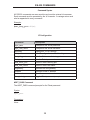
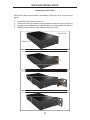
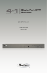
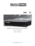
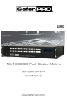
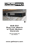
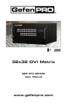
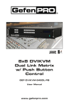
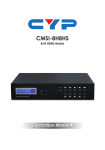
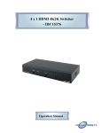
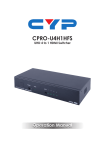
®
8x1 DPKVM
Switcher
EXT-DPKVM-841
User Manual
www.gefen.com
ASKING FOR ASSISTANCE
Technical Support:
Telephone
Fax
(818) 772-9100
(800) 545-6900
(818) 772-9120
Technical Support Hours:
8:00 AM to 5:00 PM Monday thru Friday.
Write To:
Gefen LLC
c/o Customer Service
20600 Nordhoff St
Chatsworth, CA 91311
www.gefen.com
[email protected]
Notice
Gefen LLC reserves the right to make changes in the hardware, packaging and
any accompanying documentation without prior written notice.
8x1 DPKVM Switcher is a trademark of Gefen LLC
© 2011 Gefen LLC, All Rights Reserved
All trademarks are the property of their respective owners
Rev A2
CONTENTS
1
Introduction
2
Operation Notes
3
Features
4
Front Panel Layout
5
Front Panel Descriptions
6
Back Panel Layout
7
Back Panel Descriptions
8
IR Remote Control Unit
8
Layout and Description
9
Installing the Battery
10
Setting the IR Channel
11 Connecting the 8x1 DPKVM Switcher
11
Wiring Diagram
12 Operating the 8x1 DPKVM Switcher
12
Front Panel Buttons and LED Indicators
12
Switching sources using the front-panel buttons
12
Switching sources using the IR Remote Control Unit
13
Switching sources using RS-232
13
Switching sources using Telnet
14 RS-232 Control
15 RS-232 Commands
15
IP Configuration
20
General Commands
23
Routing Commands
24 Telnet Control
26 Firmware Update
27 Rack Ear Installation
28 Specifications
29 Warranty
INTRODUCTION
Congratulations on your purchase of the 8x1 DPKVM Switcher. Your complete
satisfaction is very important to us.
Gefen
Gefen is a unique product line catering to the growing needs for innovative home
theater solutions. We specialize in total integration for your home theater, while
also focusing on going above and beyond customer expectations to ensure you
get the most from your hardware. We invite you to explore our distinct product
line and hope you find your solutions. Don’t see what you are looking for here?
Please call us so we can better assist you with your particular needs.
The Gefen 8x1 DPKVM Switcher
Easily switch between eight computers using DisplayPort with the Gefen 8x1
DPKVM Switcher.
The rack-mountable Gefen 8x1 DPKVM Switcher offers an economical solution
for switching between eight different computers to one display location. In addition, USB peripherals and audio are carried at the same time from each source
making this a very versatile solution.
Eliminating the need to purchase many displays, keyboards and other accessories for each computer in a studio or professional environment, this versatile
solution saves money, supports both Mac and PC-type computers, and offers
uncluttered and increased desktop space.
The 8x1 DPKVM Switcher outputs are: One DisplayPort, two USB 2.0 ports
(used for keyboard, mouse and other USB 2.0 peripherals) and an analog L/R
audio. This Switcher can be controlled using front-panel discrete switching, the
included IR Remote control, or the RS-232 port for switching automation or via
Ethernet.
The 8x1 DPKVM Switcher is compatible with all operating systems using DisplayPort and USB.
How It Works
Connect the eight included 6-foot DisplayPort cables between the computers
and the Switcher inputs. Connect the eight included USB cables between the
computers and the USB inputs. Connect the eight included audio cables between
the computers and the audio inputs. Connect the Switcher output to the monitor
using a DisplayPort cable. Connect the Switcher USB outputs to the USB peripherals. Connect the Switcher audio cables to the audio devices. Connect the
included 5V DC locking power supply to the 8x1 Switcher and connect the AC
power cord to an available electrical outlet. The currently selected source will be
displayed.
1
OPERATION NOTES
READ THESE NOTES BEFORE INSTALLING OR
OPERATING THE 8X1 DPKVM SWITCHER
•
The 8x1 DPKVM Switcher supports Pass-through EDID. The Switcher will
use the EDID from the currently active input.
•
Dual Link resolutions up to 2560 x 1600 are supported.
•
HDCP content is not supported.
•
This Switcher does not support DHCP.
•
The default IR channel for both the Switcher and the IR Remote Control Unit
is channel 0. See page 10 for more information.
2
FEATURES
Features
•
Front-panel switching using discrete select buttons
•
Supports resolutions up to 2560 x 1600
•
Supports RGB and YCbCr color spaces
•
RS-232 control
•
IP control
•
IR remote control
•
Supports USB 2.0 with backward-compatibility for USB 1.1
•
Jack for external IR Receiver (EXT-RMT-EXTIR)
•
Save space on your desktop
•
Rack-mountable
Package Includes
(1) 8x1 DPKVM Switcher
(8) 6 ft. DisplayPort cables
(8) 6 ft. USB 2.0 cables (A - B)
(8) 6 ft. 3.5 mm mini-stereo audio cables
(1) IR Remote Control Unit (EXT-RMT-8IR)
(1) 5V / 4A DC Locking Power Supply (EXT-PS54AULP)
(1) Set Rack ears
(1) User Manual
3
1
Front Panel
2
3
4
FRONT PANEL LAYOUT
4
FRONT PANEL DESCRIPTIONS
1
Input Indicators (1 - 8)
Each of these LED indicators glows bright blue according to the input selection
(see Input Buttons, below)
2
IR
Receives IR signals from the included IR Remote Control Unit.
3
Input Buttons (1 - 8)
Pressing each of these buttons selects the desired input source (1 - 8).
4
Power
This LED indicator will glow bright red when the unit is powered.
5
1
2
10
9
Back Panel
8
3
4
7
6
5
BACK PANEL LAYOUT
6
BACK PANEL DESCRIPTIONS
1
5V DC
Connect the included 5V DC locking power supply to this receptacle.
2
In 1 - In 8
Each of these ports will accept a standard DisplayPort source device.
3
Ext IR
Connect an IR extender cable to this port.
4
USB Out (1 - 2)
Connect USB devices (e.g. mouse devices, keyboards, etc.) to these ports.
5
Ethernet
Use an Ethernet cable to connect the Switcher to a network in order to
communicate via Telnet.
6
RS-232 Serial Port
This port is used for serial communication using an RS-232 control device. For
details, refer to page 14.
7
USB In (1 - 8)
Connect USB source devices to these ports.
8
DP Out
This port will accept a single standard DisplayPort output device. The currently
selected DisplayPort input source will be output via this port.
9
Audio Out
Connect an audio output device to this connectors using a 3.5 mm mini-stereo
cable. The audio output will be for the currently selected input source.
10 Audio In (1 - 8)
Connect up to eight (8) audio source devices to these ports using the included
3.5 mm mini-stereo cables.
7
IR REMOTE CONTROL UNIT
Layout and Description
1
2
1
Activity Indicator
This LED will be activated momentarily each time a button is pressed.
2
Source Selection Buttons (1 - 8)
These buttons are used to select which source is routed to a monitor.
NOTE: An Activity Indictor that flashes quickly while holding down any
one of the eight buttons indicates a low battery. Replace the IR Remote
Control battery as soon as possible.
8
IR REMOTE CONTROL UNIT
Installing the Battery
1.
Remove the battery cover on the back of the IR Remote Control Unit.
2.
Insert the included battery into the open battery slot. The positive (+) side of
the battery should be facing up.
3.
Replace the battery cover.
The Remote Control unit ships with two batteries. One battery is required for
operation and the other battery is a spare.
Battery Slot
WARNING: Risk of explosion if battery is replaced by an incorrect type.
Dispose of used batteries according to the instructions.
9
IR REMOTE CONTROL UNIT
Setting the IR Channel
In the event that IR commands from other remote controls interfere with the
supplied IR Remote Control unit, changing the IR Remote Control’s IR channel
will fix the problem. The IR Remote Control unit has a bank of DIP switches used
for setting the IR channel. The DIP switch bank is located underneath the battery
cover.
Left: Picture of the
opened rear battery
compartment of the IR
remote showing the
exposed DIP Switch
bank between the battery
chambers.
Corresponding DIP Switch Settings for each IR Channel
IR Channel 0
(default)
IR Channel 1
ON
1
2
IR Channel 2
ON
1
IR Channel 3
ON
2
1
2
ON
1
2
It is important that the IR channel on the Remote Control unit, matches the IR
channel set on the 8x1 DPKVM Switcher. For example, if both DIP switches on
the IR Remote Control unit are set to IR channel 0 (both DIP switches down),
then the 8x1 DPKVM Switcher must also be set to IR channel 0. See page 21 on
how to change the IR channel on the 8x1 DPKVM Switcher.
10
CONNECTING THE 8X1 DPKVM SWITCHER
How to Connect the 8x1 DPKVM Switcher
1
Connect up to eight (8) DisplayPort source devices to the DisplayPort inputs
on the back panel of the Switcher using DisplayPort cables.
2
Connect a DisplayPort-supported display to the DisplayPort output on the
back panel of the Switcher.
a
OPTIONAL: To use the RS-232 communication feature, connect an
RS-232 cable between the Switcher and RS-232 host controller.
b
OPTIONAL: To communicate with the Switcher using Telnet, connect
an Ethernet cable from the Ethernet jack on the back of the Switcher
to the network. See page 24 for more information on using the Telnet
feature.
c
OPTIONAL: To extend the range of the IR control, connect an IR
Extender (Gefen part no. EXT-RMT-EXTIR) to the back of the Switcher.
3
Connect the included 5V locking power supply to the power receptacle on
the 8x1 DPKVM Switcher
4
Connect the opposite end of the power supply to an open wall socket power
source.
Wiring Diagram for the 8x1 DPKVM Switcher
MINI STEREO AUDIO CABLE
DISPLAYPORT CABLE
Computer
RS-232 CABLE
Computer
USB CABLE
Computer
ETHERNET
Computer
IR
Computer
IR Extender
Computer
Computer
Computer
DisplayPort KVM Switcher
DisplayPort
Display
USB Mouse
RS-232 Controller
USB Keyboard
Powered Speakers
Router
EXT-DPKVM-841
ATTENTION: This product should always be connected to a grounded
electrical socket.
11
OPERATING THE 8X1 DPKVM SWITCHER
Front Panel Buttons and LED Indicators
The front panel of the 8x1 DPKVM Switcher has a set of eight (8) LED
indicators, displaying which input (source) is being displayed. Each of these LED
indicators corresponds to one of the push-buttons on the front panel.
Switching sources using the front-panel buttons
Example: Switch to input 5 using the front-panel buttons:
1
Press button 5 on the front panel of the 8x1 DPKVM Switcher.
2
The LED indicator for input 5 will glow bright blue on the front panel.
1
2
Switching sources using the IR Remote Control
Example: Switch to Input 1 using the IR Remote Control:
1
Press button 1 on the IR Remote Control Unit. The Activity Indicator on
the IR Remote Control Unit will glow yellow, indicating that a button was
pressed.
2
The LED indicator for input 1 will glow bright blue.
2
1
12
OPERATING THE 8X1 DPKVM SWITCHER
Switching sources using RS-232
Configure the Switch for use with RS-232 (see page 14 for details).
Example: Switch to input 4 using RS-232
1
Use the command r 4 to route the Switcher to Input 4. See page 15 for
important information on RS-232 commands. RS-232 commands are
case-sensitive.
2
The LED indicator for Input 4 will glow bright blue on the front panel.
1
2
r 4
Route to Input 4
Switching sources using Telnet
Configure the Switch for use with Telnet. See page 24 for details.
Example: Switch to Input 2 using the Telnet protocol
1
Use the command r 2 to route the Switcher to Input 2.
2
The LED indicator for Input 2 will glow bright blue.
1
2
Type Cmd: r 2
Route to Input 2
13
RS-232 CONTROL
Only pins 2 (Receive), 3 (Transmit), and 5 (Ground) are used for communication.
A null-modem adapter should not be used with this product.
54321
12345
9876
6789
Only Pins 2 (RX), 3 (TX), and 5 (Ground) are used on the RS-232 serial interface
Serial Port Settings
Bits per second ............................................................................................ 19200
Data bits ............................................................................................................... 8
Parity ............................................................................................................. None
Stop bits ................................................................................................................1
Flow Control .................................................................................................. None
IMPORTANT: When sending RS-232 commands, a carriage return and
a line feed character must be included at the end of each line.
NOTE: Only pins 2 (Receive), 3 (Transmit), and 5 (Ground) are used
for communication. A null-modem adapter should not be used with this
product.
14
RS-232 COMMANDS
Command Syntax
All RS-232 commands are case-sensitive and must be entered in lowercase.
Each command must be preceded by the ‘#’ character. A carriage return must
also be appended to every command.
Example:
#set_http_port 80[CR]
IP Configuration
Command
Description
#get_pass
Prompts for the Telnet password
#get_user_name
Prompts for the Telnet username
#ipconfig
Displays all TCP/IP settings
#rstip
Sets IP configuration to default settings
#set_http_port
Sets the Web server listening port
#set_pass
Sets the Telnet password
#set_telnet_port
Sets the Telnet listening port
#set_user_name
Sets the Telnet user name
#sgateway
Specifies the new gateway
#sipadd
Specifies a new IP address
#snetmask
Specifies a new net mask
#use_telnet_pass
Toggles Telnet password prompt
#GET_PASS Command
The #GET_PASS command prompts for the Telnet password.
Syntax:
#get_pass
Parameters:
None
15
RS-232 COMMANDS
#GET_USER_NAME Command
The #GET_USER_NAME command prompts for the Telnet username.
Syntax:
#get_user_name
Parameters:
None
#IPCONFIG Command
The #IPCONFIG command displays all TCP/IP settings.
Syntax:
#ipconfig
Parameters:
None
#RSTIP Command
The #RSTIP command resets the IP configuration to the default settings.
Syntax:
#rstip
Parameters:
None
16
RS-232 COMMANDS
#SET_HTTP_PORT Command
The #SET_HTTP_PORT command sets the Web server listening port.
Syntax:
#set_http_port param1
Parameters:
param1
Port
[0 - 255]
#SET_PASS Command
The #SET_PASS command sets Telnet password.
Syntax:
#set_pass param1
Parameters:
param1
String
Notes:
The maximum length of the password string is 20 characters.
#SET_TELNET_PORT Command
The #SET_TELNET_PORT command sets the Telnet server listening port.
Syntax:
#set_telnet_port param1
Parameters:
param1
Port
[0 - 255]
17
RS-232 COMMANDS
#SET_USER_NAME Command
The #SET_USER_NAME command sets the Telnet user name.
Syntax:
#set_user_name param1
Parameters:
param1
String
Notes:
The maximum length of the username string is 20 characters.
#SGATEWAY Command
Specifies the new IP gateway. Dot-decimal notation must be used when specifying the IP address. A reboot is required after the new IP gateway address has
been assigned.
Syntax:
#sgateway param1.param2.param3.param4
Parameters:
param1
Gateway address
[0 - 255]
param2
Gateway address
[0 - 255]
param3
Gateway address
[0 - 255]
param4
Gateway address
[0 - 255]
Example:
#sgateway 192.168.1.1
18
RS-232 COMMANDS
#SIPADD Command
The #SIPADD command specifies a new IP address. Dot-decimal notation must
be used when specifying the IP address. A reboot is required after the new IP
address is set.
Syntax:
#sipadd param1.param2.param3.param4
Parameters:
param1
IP address
[0 - 255]
param2
IP address
[0 - 255]
param3
IP address
[0 - 255]
param4
IP address
[0 - 255]
Example:
#sipadd 192.168.2.240
#SNETMASK Command
The #SNETMASK command specifies a new net mask. Dot-decimal notation
must be used when specifying the IP address. A reboot is required after the new
IP address is set.
Syntax:
#snetmask param1.param2.param3.param4
Parameters:
param1
IP address
[0 - 255]
param2
IP address
[0 - 255]
param3
IP address
[0 - 255]
param4
IP address
[0 - 255]
Example:
#snetmask 255.255.255.0
19
RS-232 COMMANDS
#USE_TELNET_PASS Command
The #USE_TELNET_PASS command enables / disabled the use of a Telnet
password during the login process.
Syntax:
#use_telnet_pass param1
Parameters:
param1
State
[0 - 1]
Value
Meaning
0
Disable password
1
Enable password
General Commands
Command
Description
#activebolo
Activates the bootloader
#fadefault
Resets the Switcher to the default routing state
#irrmtadd
Sets the IR address for the Switcher
#lockpower
Toggles the lock power state
#stbymode
Toggles Standby (power OFF) Mode
#ACTIVEBOLO Command
The #ACTIVEBOLO function activates the bootloader. This command is required
in order to begin the firmware update procedure. See page 26 for details.
Syntax:
#activebolo
Parameters:
None
Notes:
This command must be executed twice, in order to active the bootloader.
20
RS-232 COMMANDS
#FADEFAULT Function
The #FADEFAULT function will reset the Switcher to the default routing settings.
Syntax:
#fadefault
Parameters:
None
#IRRMTADD Command
The #IRRMTADD sets the IR channel. The IR channel for the Switcher and the
IR Remote Control Unit must be the same.
Syntax:
#irrmtadd param1
Parameters:
param1
State
[0 - 3]
Value
Meaning
0
IR channel 0
1
IR channel 1
2
IR channel 2
3
IR channel 3
21
RS-232 COMMANDS
#LOCKPOWER Command
The #LOCKPOWER enables/disables the power lock state. Enabling this
feature will store the 5V status for each input prior to shutting the unit down.
This preserves the 5V state when the unit is restarted.
Syntax:
#lockpower param1
Parameters:
param1
State
[0 - 1]
Value
Meaning
0
Disable Power Lock
1
Enable Power Lock
#STBYMODE Command
The #STBYMODE command toggles the Standby Mode state. When the
Switcher is powered OFF (not unplugged), then the unit is in Standby Mode.
Executing this command from Standby Mode will power ON the Switcher.
Syntax:
#stbymode param1
Parameters:
param1
Mode
[0 - 1]
Value
Meaning
0
Normal Mode
1
Standby Mode
22
RS-232 COMMANDS
Routing Commands
The following command does not require the ‘#’ character. A carriage return must
be added to the end of the command.
Command
Description
R
Routing command
R Command
The R command switches to the specified input.
Syntax:
r param1
Parameters:
param1
DisplayPort Input
23
[1 - 4]
TELNET CONTROL
The Gefen 8x1 DPKVM Switcher supports Telnet for controlling the Switcher
over a network. To access this feature, an IP address, subnet, gateway, and port
numbers need to be set correctly. Consult the network administrator to obtain the
proper IP address and settings for this product to properly communicate with the
Switcher over a network.
The Telnet control must be configured using RS-232 commands. Once properly
configured, enter the IP address that was assigned to the Switcher using a
terminal program or other Telnet client.
1.
Connect the Switcher to a computer using RS-232.
2.
Use a terminal emulation program (e.g. HyperTerminal, PuTTY, Indigo,
etc.) to connect to the Switcher. See page 14 for information on RS-232
configuration.
IMPORTANT: When using HyperTerminal under Windows XP,
the LF (line feed) character option must be enabled.
3.
Apply power to the Switcher. Information similar to the following will be
displayed in the terminal window:
===================================================
GEFEN
DISPLAY PORT 841
FW version: 1.3
===================================================
4.
Use the #ipconfig command to display the current IP settings. The factory
(default) settings are displayed below:
#ipconfig
------------------- TCP/IP settings --------------MAC addr
=
IP addr
=
Net Mask
=
Gateway
=
Web Server Port
=
Telnet Server Port
=
Telnet password on login
00:1C:91:02:40:00
192.168.0.70
255.255.255.0
192.168.0.1
80
23
is set to ON
Note that the Telnet password is set to ON. A user name and password can
be set for additional security. This option can also be disabled. See page 20
for details.
24
TELNET CONTROL
5.
Use the #sipadd command to set the IP address for the Switcher. Check
with a network administrator to obtain an available address, if necessary.
DHCP is not supported by this Switcher.
#sipadd 192.168.2.234
New IP set to: 192.168.2.234
After setting the IP address, power-cycle the Switcher for the changes to
take effect.
IMPORTANT: All IP configuration changes will require the
Switcher to be power-cycled.
6
Specify the IP of the Switcher in the Telnet client. In this example, the IP
address is set to 192.168.2.234. Once connected to the Switcher, the Telnet
client will display a screen similar to the following:
----------- Welcome to DP841 Telnet Server ---------You are user number 1 of 3 allowed.
You will be disconnected after 10 minutes of inactivity.
Login: Admin
Password: Admin
Type Cmd:
By default, the user name and password options are enabled by use of
the #use_telnet_pass command (see page 20). Once this command
is enabled, the Switcher will prompt for both the user name and password.
The password cannot be disabled from the login process. Once logged in,
the Type Cmd prompt will be displayed.
The Telnet interface uses the same commands and syntax that are used with
RS-232 control. See the command list, starting on page 15.
25
FIRMWARE UPDATE
Firmware Update Procedure
Any terminal emulation program can be used to perform the upgrade
process. The instructions below is outlined for Windows® HyperTerminal.
1.
Connect an RS-232 cable between the Switcher and the computer running
the terminal program. Verify the correct serial port settings (see page 14).
2.
Type the #activebolo command then press the [ENTER] key.
3.
Repeat Step 2.
The following will be displayed on the screen:
================== Main Menu ========================
Download new program -------- 1
Cancel ---------------------- 2
=====================================================
4.
Press [1] on the computer keyboard to begin downloading program to the
htemporary memory.
5.
The following message will be displayed:
Waiting for the file to be sent ... (press ‘a’ to abort)
6.
In Hyperterminal, click Transfer > Send File...
7.
Click Browse... and select the .bin file to be uploaded (e.g. 1x4splitter.bin).
8.
Select the Ymodem protocol.
9.
Click Send on the Send File dialog box.
10. After a few moments, a message will appear in Hyperterminal:
Programming Completed Successfully!
26
RACK EAR INSTALLATION
Installing the Rack Ears
Rack mount ears are provided for installation of this unit into a 1U rack mount
space.
1.
2.
3.
4.
Locate the side screws on the unit.
Remove the front 2 screws that are located closest to the front of the unit.
Using the removed screws, screw the rack mounting bracket into the unit.
Repeat the procedure on the opposite side of the unit.
Front of unit
Rear of unit
27
SPECIFICATIONS
Maximum Pixel Clock................................................................................360 MHz
Video Input Connectors.......................................................(8) DisplayPort, female
Video Output Connector......................................................(1) DisplayPort, female
USB Input Connectors..............................................................(8) USB 2.0 Type B
USB Output Connectors............................................................(2) USB 2.0 Type A
Audio Input Connectors.......................................................(8) 3.5 mm mini-stereo
Audio Output Connector.......................................................(1) 3.5 mm mini-stereo
RS-232 Connector.........................................................................(1) DB-9, female
Ethernet Connector................................................................... (1) RJ-45, shielded
IR Extender Connector........................................................ (1) 3.5 mm mini-stereo
Power Supply .............................................................................................. 5V DC
Power Consumption ...................................................................... 10 Watts (max.)
Dimensions.................................................................. 17.1” W x 1.75” H x 4.25” D
Shipping Weight ............................................................................................ 4 lbs.
28
WARRANTY
Gefen warrants the equipment it manufactures to be free from defects in material
and workmanship.
If equipment fails because of such defects and Gefen is notified within two (2)
years from the date of shipment, Gefen will, at its option, repair or replace the
equipment, provided that the equipment has not been subjected to mechanical,
electrical, or other abuse or modifications. Equipment that fails under conditions
other than those covered will be repaired at the current price of parts and labor in
effect at the time of repair. Such repairs are warranted for ninety (90) days from
the day of reshipment to the Buyer.
This warranty is in lieu of all other warranties expressed or implied, including
without limitation, any implied warranty or merchantability or fitness for any
particular purpose, all of which are expressly disclaimed.
1.
Proof of sale may be required in order to claim warranty.
2.
Customers outside the US are responsible for shipping charges to and from
Gefen.
3.
Copper cables are limited to a 30 day warranty and cables must be in their
original condition.
The information in this manual has been carefully checked and is believed to
be accurate. However, Gefen assumes no responsibility for any inaccuracies
that may be contained in this manual. In no event will Gefen be liable for
direct, indirect, special, incidental, or consequential damages resulting from
any defect or omission in this manual, even if advised of the possibility of such
damages. The technical information contained herein regarding the features and
specifications is subject to change without notice.
For the latest warranty coverage information, refer to the Warranty and Return
Policy under the Support section of the Gefen Web site at www.gefen.com.
PRODUCT REGISTRATION
Please register your product online by visiting the Register Product page
under the Support section of the Gefen Web site.
29
Rev A2
20600 Nordhoff St., Chatsworth CA 91311
1-800-545-6900
818-772-9100
www.gefen.com
Pb
This product uses UL listed power supplies.
fax: 818-772-9120
[email protected]