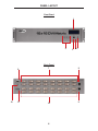
1
www.gefen.com
ASKING FOR ASSISTANCE
Technical Support:
Telephone
(818) 772-9100
(800) 545-6900
Fax
(818) 772-9120
Technical Support Hours:
8:00 AM to 5:00 PM Monday thru Friday PST
Write To:
Gefen, LLC
c/o Customer Service
20600 Nordhoff St
Chatsworth, CA 91311
www.gefen.com
[email protected]
Notice
Gefen, LLC reserves the right to make changes in the hardware, packaging and
any accompanying documentation without prior written notice.
16x16 DVI Matrix is a trademark of Gefen, LLC
© 2011 Gefen, LLC. All Rights Reserved
All trademarks are the property of their respective owners.
CONTENTS
1
Introduction
2
Operation Notes
3
Features
4
Panel Layout
5
Panel Descriptions
6
Connecting And Operating The 16x16 DVI Matrix
7
Front Panel Display
9
RMT-16416IR Remote Description
10 RMT-16416IR Remote Installation
11 RMT-16416IR Remote Configuration
12 Standby Mode Feature
13 EDID Management Feature
14 RS-232 Serial Control Interface
15 RS-232 Serial Control Commands
29 IP Control - Main Page
30 IP Control - Manage EDID
33 IP Control - Masking
34 IP Control - IP Configuration
35 IP Control - Backup/Restore & Power Management
36 IP Control - I/O Management Without The Web Interface
40 Firmware Update
42 Warning Messages
44 Specifications
45 Warranty
46 Licensing
INTRODUCTION
Congratulations on your purchase of the 16x16 DVI Matrix. Your complete
satisfaction is very important to us.
Gefen
Gefen delivers innovative computer and electronic solutions that harness
integration, extension, distribution and conversion technologies. Gefen’s
reliable, plug-and-play products supplement cross-platform computer systems,
professional audio/video environments and HDTV systems of all sizes with hardworking solutions that are easy to implement and simple to operate.
The Gefen 16x16 DVI Matrix
Now you can easily combine sixteen cross-platform computers and sixteen digital
displays using the 16x16 DVI Matrix. The 16x16 DVI Matrix provides a simple,
reliable and highly effective method of routing multiple computer workstations.
Each computer is capable of displaying video on any one of the 16 monitors.
There are 4 methods of controlling the Matrix - by using the front panel buttons,
the IR remote, a built-in RS-232 interface, or through IP Control over a local area
network.
How It Works
The 16x16 DVI Matrix has sixteen DVI inputs and sixteen DVI outputs. Connect
your sixteen computers to the DVI input ports on the Matrix’s input side. Connect
the Matrix’s sixteen DVI outputs to the displays. Connect the power supply to the
Matrix and connect the power cord to an available wall outlet. The connected
displays will show video according to the selection.
NOTE: This device only supports DVI-D.
1
OPERATION NOTES
READ THESE NOTES BEFORE INSTALLING OR
OPERATING THE 16X16 DVI MATRIX
•
The 16x16 DVI Matrix will not pass HDCP content.
•
There is no internal scaling in the 16x16 DVI Matrix. All of the attached
monitors must be able to display the resolutions output by the source
devices. For maximum compatibility it is recommended that only one
compatible/common resolution be used by all of the source devices.
•
Advanced EDID features and IP configuration features are accessible via the
RS-232 serial communication port. Please see page 14 for more information.
•
Routing and EDID features can be accessed via a web browser using the IP
control feature, built into the 16x16 DVI Matrix.
2
FEATURES
Features
•
Increases productivity by providing access to 16 displays from any 16
computers.
•
Web-based control switching
•
Maintains beautiful, sharp resolutions up to 1920x1200.
•
Serial RS-232 port for remote control via a computer or control automation
device.
•
Supports DDWG standards for DVI monitors
Package Includes
(1)
(16)
(1)
(1)
(1)
(1)
16x16 DVI Matrix
6-foot DVI cables
IR Remote (EXT-RMT-16416IR)
24 V DC Power Supply
Set of Rack Ears
User Manual
3
PANEL LAYOUT
Front Panel
1
2
3
45
Back Panel
6
12
11
7
10
4
8
9
PANEL DESCRIPTIONS
1
Main LCD Display
This 2 line 16 character display will display status information and is also used to
manage the display/source routes.
2
Control Buttons
These buttons are used to navigate the functions of the 16x16 DVI Matrix. For
complete details on these controls and how they are used, please see page 7
and 8.
3
Infrared (IR) Receiver
This IR receiver will accept commands from the RMT-16416IR remote control.
Line-of-sight between this receiver and the remote controls needs to be
preserved for proper operation.
4
Power LED Indicator
This LED indicator will be active when the included 24V DC power supply is
properly connected to the unit.
5
Cancel Button
This button is used to return the user to the main status screen once a routing
change has been initiated and the user decides to not continue with the change.
6
RS-232 Serial Communications Interface
This interface was designed to accept commands from an external control
system. This port will allow switching commands as well as EDID management
and configuration operations. Please see page 14 for more information.
7
DVI Output Ports 1-16
These outputs are used to connect up to 16 DVI-capable displays.
8
24V DC Power Receptacle
The port will accept power from the included 24V DC power supply.
9
10/100 Ethernet Control Interface
This port is used to connect the 16x16 DVI Matrix to a network for IP control.
Please see page 29 for more information.
10 DVI Input Ports 1-16
These inputs are used to connect up to 16 DVI-capable sources.
11 DIP Switch Configuration Bank
These DIP switches are not used and are for future use.
12 IR Extender Jack
Accepts an optional IR Extender which allows relocation of the IR receiver up to
6 feet away from the Matrix.
5
CONNECTING AND OPERATING THE 16X16 DVI MATRIX
How to Connect the 16x16 DVI Matrix
1.
Connect up to 16 DVI source devices to the DVI inputs on the rear panel of
the 16x16 DVI Matrix using DVI cables.
2.
Connect up to 16 DVI capable display to the DVI outputs on the rear panel of
the 16x16 DVI Matrix using DVI cables.
3.
Connect the included 24V DC power supply to the power input receptacle
on the rear panel of the 16x16 DVI Matrix. Connect the opposite end of the
cable into a open wall power socket.
How to Operate the 16x16 DVI Matrix
The 16x16 DVI Matrix offers a number of control options. The following options
can be used to control basic routing functions of the 16x16 DVI Matrix:
1.
Front Panel Control Buttons - Page 7 - 8
2.
RMT-16416IR Remote Control - Page 9 - 11
3.
RS-232 Serial Control - Page 14 -28
4.
IP Control - Page 29-35
6
FRONT PANEL DISPLAY
MAIN DISPLAY
The Main Display of the 16x16 DVI Matrix is a 16 character 2 line display. This
display will show the standby screen and will also be used to aid in performing
routing commands. After the Matrix has been turned on, the following screen will
be displayed:
This screen will display the company and product name.
Pressing the ◄ will display the firmware version:
Pressing the ◄ button again will display the bootloader version:
The ► button can also be used to switch the LCM display between firmware
version and the bootloader version.
7
FRONT PANEL DISPLAY
ROUTING
To route sources to a display:
Starting at the standby screen, press the SELECT button. The display selection
screen will now be displayed:
On this screen use the ◄ or ► buttons to select the desired display that will
have a source routed to it in the next step. Once selection is complete press the
SELECT button to confirm the selection. To cancel this operation at this time
press the CANCEL button.
Once the display has been selected and confirmed, the source can then be
chosen which will be routed to the selected display. The following is the source
selection screen:
On this screen use the ◄ or ► buttons to select the desired display that will be
routed to the display selected in the previous step. Once selection is complete
press the SELECT button to confirm the selection. The selected source will now
be routed to the selected display. Once the routing is complete, the user will be
returned to the standby screen. To cancel this operation at this time press the
CANCEL button.
8
RMT-16416IR REMOTE DESCRIPTION
RMT-16416IR
1
2
1
LED Button Press Indicator
This LED will activate momentarily upon each button press. This visual indicator
is to inform the user that a command has been sent by the IR remote control.
2
Display and Source Selection Buttons
These buttons will be used to send display and source selections to the 16x16
DVI Matrix.
Routing Sources to Displays
Issuing a routing command is a two step process. The first step will be to select a
the display (1-16) which a source will be routed to in the next step. Once the display
has been entered, the source can then be selected. Select the source (1-16) which
will be routed to the display selected in the previous step. For example, to route the
source connected to input 6 to the display connected to output 4 the input steps
would be the following:
1
Press button 4 (display) on the RMT-16416IR remote control.
2
Press button 6 (source) on the RMT-16416IR remote control.
3
The source will immediately be routed to the display.
9
RMT-16416IR REMOTE INSTALLATION
To use the RMT-16416IR remote, remove the battery cover on the back of the
remote to reveal the battery compartment. Insert the included battery into the open
battery slot. The positive (+) side should be facing up. Ensure that both DIP (Dual
In-line Package) switches are in the OFF position. Replace the battery cover. The
remote ships with 2 batteries. One battery is needed for operation and the other
battery is complimentary.
Empty Battery Slot
IR Code Dip Switches
10
RMT-16416IR REMOTE CONFIGURATION
How to Resolve IR Code Conflicts
In the event that IR commands from other remote controls conflict with the RMT16416IR remote control, changing the remote channel will alleviate this issue.
The RMT-16416IR remote contains a set of DIP (Dual In-line Package) switches
for setting the IR channel for the remote.
The DIP Switch bank on the RMT-16416IR is located underneath the battery
cover.
IMPORTANT: The IR channel on the Matrix must match the IR channel on the
remote. Please see page 26 for details.
Remote Channel 1:
Default
Remote Channel 2:
1
2
Remote Channel 3:
2
1
2
Remote Channel 4:
1
2
Left: Picture of the opened rear battery
compartment of the RMT-16416IR remote
showing the exposed DIP Switch bank
between the battery chambers.
11
1
STANDBY MODE FEATURE
Invoking Standby Mode
To place the 16x16 DVI Matrix into Stand-by mode, simultaneously press and
hold the SELECT and CANCEL buttons for 5 seconds, then release.
Press Select
and Cancel
Simultaneously
Exiting Standby Mode
To exit Standby Mode and return to normal operation, press and hold any button
on the front panel for 5 seconds, then release.
Standby Mode can also be invoked using RS-232 by using the #STBYMODE
function. Please see page 28 for details.
12
EDID MANAGEMENT FEATURE
EDID. What is it and what is it used for?
Under normal circumstances, a source device (digital and analog) will require
information about a connected device/display to assess what resolutions
and features are available. The source can then tailor its output to send
only resolutions and features that are compatible with the attached device/
display. This information is called EDID (Extended Display Information Data)
and a source device can only accept and read one EDID from a connected
device/display. Likewise, the source an only output one resolution for use by a
connected device/display.
Why is EDID so important with the 16x16 DVI Matrix?
The 16x16 DVI Matrix is a complex piece of technology that replicates and
switches between multiple inputs and outputs. Each connected source device will
require one EDID to read. EDID management is carefully handled by the 16x16
DVI Matrix to provide a single EDID for each source to read.
What options do I have to manage the EDID in the 16x16 DVI Matrix?
First, it is important to note that each source device can only output one video/
audio signal type. This includes resolutions and timings. When multiple devices/
displays are used, such as with the 16x16 DVI Matrix, it is important to use
devices/displays that have similar or compatible resolutions and features. This
will ensure that the single video/audio signal produced by the source device is
accepted by all of the connected output devices/displays.
The user has the option, through utilization of the RS-232 serial interface, to
choose how the unit will manage the EDID from multiple DVI devices/displays.
Therefore the user has some control over the resolutions and features that
the source devices will output. The 16x16 DVI Matrix has a LOCAL EDID
management mode that will control how the EDID information is handled.
How do I change EDID modes in the 16x16 DVI Matrix?
EDID modes and IP configuration is managed via the RS-232 serial
communications port. See page 14 for more information on the RS-232 serial
communication features.
13
RS-232 SERIAL CONTROL INTERFACE
What features are available via the RS-232 serial communications port?
The GefenPRO 16x16 DVI Matrix can accept commands through the RS-232
serial communications port located on the rear panel. The current RS-232 control
features are:
•
Switching/routing of inputs to outputs without the IR remote control.
•
Managing the EDID bank and EDID that is loaded into the LOCAL EDID.
•
Upload new EDID’s to the EDID bank or directly to the LOCAL EDID
location.
•
Manage IP settings.
How do I use these features?
These features were initially intended for utilization by custom installers in
automated setups. However, these features can be tested and used by using any
Windows PC with a terminal program.
What pins are used for communication with the GefenPRO 16x16 DVI
Matrix?
Only pins 2 (Receive), 3 (Transmit), and 5 (Ground) are used for communication.
A null-modem adapter should not be used with this product.
54321
12345
9876
6789
Only Pins 2 (RX), 3 (TX), and 5 (Ground) are used on the RS-232 serial interface
RS-232 Settings
Bits per second ............................................................................................ 19200
Data bits ............................................................................................................... 8
Parity ............................................................................................................. None
Stop bits ................................................................................................................1
Flow Control .................................................................................................. None
14
RS-232 SERIAL CONTROL COMMANDS
RS-232 Features
RS-232 remote functions are used to control of this product’s features. Features
include input to output routing, EDID storage, EDID management, etc.
Functions Syntax
The syntax for each function is always the same:
#Character as the start flag → Function name → Space ( _ ) as function name
end flag → Parameter 1 → Space → Parameter n → Carriage Return ( \r ) →
Sample:
#FunctionName_param1_param2_param3_param4...\r
Syntax is NOT case sensitive.
Commands
Simplified syntax was used for command implementation for faster operation with
the device: # character – isn’t needed, the command name is reduced to 1 letter.
The commands are not case-sensitive.
Command
Description
R
Routing command
S
Routes a single input to all outputs
M
Returns the current routing status of matrix
F
Toggle 5V fiber optic extender feature
R Command
The R command allows specific routing of inputs and outputs.
Syntax:
r param1 param2
Parameters:
param1
DVI Ouput
[1 - 16]
param2
DVI Input
[1 - 16]
15
RS-232 SERIAL CONTROL COMMANDS
S Command
The S command routes a single input to all 16 DVI outputs.
Syntax:
s param1
Parameters:
param1
Input
[0 - 16]
Notes:
Setting param1 to a value of 0 will place the matrix in one-to-one mode. This
means that Input1 will be routed to Output1, Input2 will be routed to Output2, and
so on.
M Command
The M command displays the current routing status of the matrix.
Syntax:
m
Parameters:
None
16
RS-232 SERIAL CONTROL COMMANDS
F Command
The F command returns the state of pin 14 of the DVI inputs.
Syntax:
f
Parameters:
None
Notes:
“High” is returned if +5V is enabled on the DVI input. “Low” is returned if +5V is
disabled on the DVI input.
Using parameters with the F Command
Permits disabling / enabling of +5V for Fiber Optic Extenders.
Syntax:
f param1 param2
Parameters:
param1
DVI input
[1 - 16]
param2
State
[0 - 1]
Value
Meaning
0
Disable
1
Enable
Notes:
Setting param1 to a value of 0 will apply the value of param2 to all inputs.
17
RS-232 SERIAL CONTROL COMMANDS
EDID Management
Function
Description
#EDIDDSTOLO
Read downstream EDID and stores into a Local EDID
#EDIDDSTOBA
Read downstream EDID and stores in EDID Bank
#EDIDBATOLO
Read downstream EDID and stores in any Local Input
#EDIDDETOLO
Stores the default EDID in any input Local EDID
#LOEDIDTOLO
Load EDID file using serial port to one of the local memories
#PRLOEDID
Prints the Local EDID
#PRDSEDID
Read downstream EDID and sends to serial port
#PRBAEDID
Read EDID from bank and sends to serial port
#PREDIDST
Print EDID from stored Local banks.
#LOCKEDID
Secures the Local EDID
#EDIDDSTOLO Function
The #EDIDDSTOLO function reads the downstream EDID and stores it to a Local
EDID.
Syntax:
#EDIDDSTOLO param1 param2 param3...param9
Parameters:
param1
A downstream display
[1 - 16]
param2
Input list
[0 - 16]
param3 - 9 (optional)
Input list
[1 - 16]
Notes:
By specifying zero as the second parameter, the downstream EDID is stored
to all 16 DVI inputs. If more than eight inputs need to be specified in order to
receive the downstream EDID, the #EDIDSDTOLO function must be executed
twice:
Example:
#EDIDDSTOLO 2 1 2 3 4 5 6 7 8 9 10 11
not permitted!
Instead, this function must be run twice:
#EDIDDSTOLO 2 1 2 3 4 5 6 7 8
#EDIDDSTOLO 2 9 10 11
18
max 8 inputs!
remaining inputs
RS-232 SERIAL CONTROL COMMANDS
#EDIDDSTOBA Function
The #EDIDDSTOBA function reads the downstream EDID and stores it to a
specified EDID bank.
Syntax:
#EDIDDSTOBA param1 param2
Parameters:
param1
A downstream display
[1 - 16]
param2
EDID bank offset
[1 - 5]
#EDIDBATOLO Function
The #EDIDBATOLO function reads an EDID from an EDID bank and stores it to
any local input.
Syntax:
#EDIDBATOLO param1 param2 param3...param9
Parameters:
param1
EDID bank offset
[1 - 5]
param2
Input list
[0 - 16]
param3 - 9 (optional)
Input list
[1 - 16]
Notes:
By specifying zero as the second parameter, the EDID in the specified bank is
copied to all sixteen inputs. If more than eight inputs need to be specified in
order to receive the EDID in the specified bank, the #EDIDBATOLO function must
be executed twice.
Example:
#EDIDBATOLO 5 2 3 4 5 6 7 8 9 10 11 12
not permitted!
Function must be run twice:
#EDIDBATOLO 5 2 3 4 5 6 7 8 9
#EDIDBATOLO 5 10 11 12
19
max 8 inputs
remaining inputs
RS-232 SERIAL CONTROL COMMANDS
#EDIDDETOLO Function
The #EDIDDETOLO function stores the Default EDID in any Local EDID.
Syntax:
#EDIDDETOLO param1 param2 param3...param9
Parameters:
param1
Input list
[0 - 16]
param2 - 9 (optional)
Input list
[1 - 16]
Notes:
By specifying 0 for param1, all inputs will receive the Default EDID or use param1
- param9 to specify individual local inputs which will receive the Default EDID.
#LOEDIDTOLO Function
The #LOEDIDTOLO function loads the specified EDID file to a specified local
input via RS-232.
Syntax:
#LOEDIDTOLO param1 param2 param3
Parameters:
param1
Input
[1 - 16]
param2
EDID size
[1 - 2]
param3
Value
Meaning
1
128 byte EDID
2
256 byte EDID
eco
[0 - 1]
Notes:
Set param1 to a value of 0 in order to specify all inputs. When using HyperTerminal, param3 must be set to 1. Otherwise, set param3 to 0.
20
RS-232 SERIAL CONTROL COMMANDS
#PRDSEDID Function
The #PRDSEDID function reads the downstream EDID and sends it to the serial
port.
Syntax:
#PRDSEDID param1
Parameters:
param1
A downstream display
[1 - 16]
#PRLOEDID Function
The #PRLOEDID function reads the local EDID of a specified input and spools it
to the serial port.
Syntax:
#PRLOEDID param1
Parameters:
param1
Input
[1 - 16]
#PRBAEDID Function
The #PRBAEDID function reads the EDID file from the specified bank and sends
it to the serial port.
Syntax:
#PRBAEDID param1
Parameters:
param1
Bank
[1 - 5]
21
RS-232 SERIAL CONTROL COMMANDS
#PREDIDST Function
The #PREDIDST function prints a table that contains details relating to the Local
EDID source and the display name.
Syntax:
#PREDIDST
Parameters:
None
#LOCKEDID Function
The #LOCKEDID function secures the Local EDID and disables the automatic
loading after power-up.
Syntax:
#LOCKEDID param1
Parameters:
param1
EDID lock state
[0 - 1]
Value
Meaning
0
Disable
1
Enable
22
RS-232 SERIAL CONTROL COMMANDS
IP Configuration
Function
Description
#SIPADD
Specifies a new IP address
#SNETMASK
Specifies a new net mask
#SGATEWAY
Specifies the new gateway
#SPORT
Specifies a new port
#PRWEBADD
Displays IP configuration and release details
#RSTIP
Sets default IP configuration
#SIPADD Function
The #SIPADD function specifies a new IP address.
Syntax:
#SIPADD param1 param2 param3 param4
Parameters:
param1
IP address
[0 - 255]
param2
IP address
[0 - 255]
param3
IP address
[0 - 255]
param4
IP address
[0 - 255]
Notes:
A reboot is required after using this function.
23
RS-232 SERIAL CONTROL COMMANDS
#SNETMASK Function
The #SNETMASK function specifies a new net mask.
Syntax:
#SNETMASK param1 param2 param3 param4
Parameters:
param1
IP address
[0 - 255]
param2
IP address
[0 - 255]
param3
IP address
[0 - 255]
param4
IP address
[0 - 255]
Notes:
A reboot is required after using this function.
#SGATEWAY Function
Specifies the new IP gateway.
Syntax:
#SGATEWAY param1 param2 param3 param4
Parameters:
param1
Gateway address
[0 - 255]
param2
Gateway address
[0 - 255]
param3
Gateway address
[0 - 255]
param4
Gateway address
[0 - 255]
Notes:
A reboot is required after using this function.
24
RS-232 SERIAL CONTROL COMMANDS
#SPORT Function
Specifies a new port.
Syntax:
#SPORT param1
Parameters:
param1
Port
[0 - 255]
Notes:
A reboot is required after using this function.
#PRWEBADD Function
Prints the current IP configuration on the screen.
Syntax:
#PRWEBADD
Parameters:
None
#RSTIP Function
Sets IP configuration to default.
Syntax:
#RSTIP
Parameters:
None
Notes:
This command requires the unit to be rebooted in order to take effect.
25
RS-232 SERIAL CONTROL COMMANDS
General Functions
Function
Description
#FADEFAULT
Reset Matrix to default settings
#RMTIRADD
Set the remote IR channel
#MASKOUT
Blanks selected outputs
#ACTIVEBOLO
Enables the boot loader
#LOCKPOWER
Toggles the lock power state
#STBYMODE
Set system to Standby Mode
#FADEFAULT Function
The #FADEFAULT function will erase all local memory EDID banks, reset default
routing, and clear all IP settings.
Syntax:
#FADEFAULT
Parameters:
None
#RMTIRADD Function
The #RMTIRADD function set the remote IR channel.
Syntax:
#RMTIRADD param1
Parameters:
param1
IR channel
[0 - 3]
Value
Meaning
0
IR channel 1
1
IR channel 2
2
IR channel 3
3
IR channel 4
26
RS-232 SERIAL CONTROL COMMANDS
#MASKOUT Function
The #MASKOUT function allows blanking of selected outputs.
Syntax:
#MASKOUT param1 param2
Parameters:
param1
Output
[1 - 16]
param2
Masking state
[0 - 1]
Value
Meaning
0
Unmask
1
Mask
Notes:
The current masking state will be lost if the unit is rebooted or power is
lost.
#ACTIVEBOLO Function
The #ACTIVEBOLO function enables the boot loader.
Syntax:
#ACTIVEBOLO
Parameters:
None
Notes:
This command must be typed twice in order to activate the boot loader.
27
RS-232 SERIAL CONTROL COMMANDS
#STBYMODE Function
The #STBYMODE places the Matrix in stand-by mode. Stand-by mode reduces
power consumption.
Syntax:
#STBYMODE param1
Parameters:
param1
State
[0 - 1]
Value
Meaning
0
Disable stand-by mode
1
Enable stand-by mode
#LOCKPOWER Function
The #LOCKPOWER enables/disables the power lock state. Enabling this feature
will store the 5V status for each input prior to shutting the unit down. This preserves the 5V state when the unit is restarted.
Syntax:
#LOCKPOWER param1
Parameters:
param1
State
[0 - 1]
Value
Meaning
0
Disable Power Lock
1
Enable Power Lock
28
IP CONTROL - MAIN PAGE
The 16x16 DVI Matrix supports IP based control via an IP Control. To access
this feature an IP address, subnet, gateway, and port need to be set on the
16x16 DVI Matrix (Default IP: 192.168.0.70 Subnet: 255.255.255.0 Gateway:
192.168.0.1 Port: 80). These settings must fall within your networks IP address
range. Please consult your network administrator to obtain the proper IP address
and settings for this product to properly communicate on your network.
The IP control setting can be configured via the RS-232 control interface. Once
this has been accomplished, access using IP Control is possible.
Simply type the IP address that was assigned to the product in a web browser to
access the Main Page. It should look like the image below.
MAIN PAGE
The Main Page will display the current status and can also be used to create
routes.
To create a new route, follow the steps below:
1.
Click on the check boxes of all of the outputs that you would like to route an
input to.
2.
Click on the input that will be routed to the selected outputs.
3.
Click the “Switch” button to initiate the change(s).
This page will automatically refresh every minute, however, at anytime the
“Refresh” button can be pressed to refresh the status of the matrix.
29
IP CONTROL - MANAGE EDID
MANAGE EDID
The Manage EDID page is used to see the status of the EDID saved in the
LOCAL storage location for each input. This section has additional tabs for
advanced EDID functions. These tabs are:
•
SET INPUT TO DEFAULT EDID
•
UPLOAD EDID (Future Implementation)
•
DOWNLOAD EDID (Future Implementation)
•
COPY EDID
This page will automatically refresh every minute, however, at anytime the
“Refresh” button can be pressed to refresh the status of the matrix.
30
IP CONTROL - MANAGE EDID
SET INPUT TO DEFAULT EDID
Pressing the “SET INPUT TO DEFAULT EDID” button will display additional
options. The following page will open.
On this page the user can select which LOCAL memory locations will be
overwritten with a built-in EDID stored in the 16x16 DVI Matrix. To set an input’s
LOCAL memory location to the default EDID follow the steps below.
1.
Select any number of inputs from the section “Select Input(s) to Set to
Default”.
2.
Click on the “Set Default EDID” button to initiate the change(s).
NOTE: After this command is complete the user will be returned to the Main
Page.
This page will automatically refresh every minute, however, at anytime the
“Refresh” button can be pressed to refresh the status of the matrix.
31
IP CONTROL - MANAGE EDID
COPY EDID
Pressing the “COPY EDID” button will display additional options. The following
page will open.
On this page, the user can select an EDID from either the LOCAL memory
locations (Input) or from a display that is currently attached to any output, and
copy that EDID to any other LOCAL memory location. This will allow the user to
manage what EDID information will be passed to each source connected to the
16x16 DVI Matrix.
To copy an EDID follow the steps below.
1.
Select an EDID from the section ”Select Source to Copy from”. The user can
choose an EDID from a display connected to one of the outputs or from an
EDID already loaded into one of the LOCAL memory locations (Input).
NOTE: Please note that only one EDID can be selected for copying.
2.
Select the LOCAL memory locations that will receive the selected EDID in
the section “Select Input(s) to Copy to”.
NOTE: Multiple LOCAL memory locations can be specified during this step.
3.
Click on the “Set EDID” button to initiate the change(s).
NOTE: After this command is complete the user will be returned to the Main
Page.
This page will automatically refresh every minute, however, at anytime the
“Refresh” button can be pressed to refresh the status of the matrix.
32
IP CONTROL - MASKING
MASKING
The Masking page is used to hide an output from displaying any video. From
this page, all outputs can be set to “Active” or “Mask”. When an output is set to
“Active”, it will function normally. When an output is set to “Mask”, it will not output
any video. To set the “Active” or “Mask” mode, follow the steps below.
1.
Select either “Active” or “Mask” for any number of desired outputs.
2.
Press the “Submit” button to initiate the change(s).
NOTE: After this command is complete the user will be returned to the Main
Page.
This page will automatically refresh every minute, however, at anytime the
“Refresh” button can be pressed to refresh the status of the matrix.
NOTE: Routing and Masking can also be managed without the Web Interface.
Please see page 36 for details.
33
IP CONTROL - IP CONFIGURATION
IP CONFIGURATION
The IP Configuration page is used to set the IP settings that will be used to
access the unit using IP Control. The following items can be configured from this
menu.
•
IP Address (Default: 192.168.0.70)
•
Subnet (Default: 255.255.255.0)
•
Gateway (192.168.0.1)
•
Port (Default: 80)
To change these settings follow the steps below.
1.
Enter the desired network information into the fields provided.
2.
Press the “Save” button to initiate the change(s).
NOTE: After this command is complete the user will be returned to the Main
Page. Setting made on this page will not take effect until the unit is restarted.
Please disconnect power from the unit and reconnect power for changes to take
effect.
At any time, the “Reset” button can be pressed to return the IP settings to their
defaults.
34
IP CONTROL - BACKUP/RESTORE & POWER MANAGEMENT
BACKUP/RESTORE
The Backup/Restore page is used to backup and restore complete setup
configurations.
NOTE: This feature will be implemented in a future release.
POWER MANAGEMENT
The Power Management page is used to set optional +5V power on an input to
power specific optional devices. The current status of this feature for each input
can be viewed on this page. To set this feature for each input follow the steps
below.
1.
Select the +5V option, either “On” or “Off” for each desired input.
2.
Click on the “Update” button to initiate the change(s).
NOTE: After this command is complete the user will be returned to the Main
Page.
This page will automatically refresh every minute, however, at anytime the
“Refresh” button can be pressed to refresh the status of the matrix.
35
IP CONTROL
I/O MANAGEMENT WITHOUT THE WEB INTERFACE
Switching and Masking without the Web Interface
The Gefen 16x16 DVI Matrix uses HTML form attributes to communicate to the
box. It uses the ‘method’ attribute with the ‘get’ value to send a command. The
Matrix has a set of values that sends a valid command to perform switching and
masking. If a command is valid, an “OK” message will be displayed. If the command is invalid, a “FAIL” message will be displayed.
Switching
Below is the syntax for the SWITCH command. The table below lists the only
values that can be entered to perform a successful switch. All values are casesensitive.
Syntax
Single Output
http://<matrix IP address>/cgibin.shtml?a=s&o=<output
value>&i=<input value>*
* Brackets should be removed and replaced with values according to the Switching Table on page 37.
Multiple Outputs
http://<matrix IP address>/cgibin.shtml?a=s&o=<output
value>&o=<output value 2>&o=<output value 3>&o=<output value
n>i=<input value> **
** When working with multiple outputs, a maximum of 16 output ports can be
entered. To specify additional ports to switch, type:
&o=<output value>
Do not use the angled brackets when typing the command.
36
IP CONTROL
I/O MANAGEMENT WITHOUT THE WEB INTERFACE
Switching Table
Input / Output Port
Value
1
0
2
1
3
2
4
3
5
4
6
5
7
6
8
7
9
8
10
9
11
A
12
B
13
C
14
D
15
E
16
F
Examples
Single Output
http://192.168.0.70/cgibin.shtml?a=s&o=0&i=0
Assigns Input 1 to Output 1.
http://192.168.0.70/cgibin.shtml?a=s&o=a&i=2
Assigns Input 3 to Output 11.
Multiple Outputs
http://192.168.0.70/cgibin.shtml?a=s&o=0&o=1&o=2&o=3&i=0
Output 1, 2, 3 and 4 will be assigned to Input 1
http://192.168.0.70/cgibin.shtml?a=s&o=5&o=8&o=a&o=d&o=e&i=a
Output 6, 9, 11, 14 and 15 will be assigned to Input 1.
37
IP CONTROL
I/O MANAGEMENT WITHOUT THE WEB INTERFACE
Masking
When masking output ports, there are two states: Active and Masked. Multiple
ports or all ports can be masked with a single command. It is possible to combine masking and activating multiple ports using a single command.
Below is the syntax for the MASK command. The table below lists the range of
values permitted to perform a successful mask. If you enter the wrong value, the
command will return a “FAIL” message. All values are case-sensitive.
Syntax
http://<matrix IP address>/cgibin.shtml?a=m&<Output
port>=<Value: Masking Command: Activate/Mask> *
* Remove the angled brackets and replace their values according to the values
provided in the table, below.
Masking Table
Output Port
Value
1
o0
2
o1
3
o2
4
o3
5
o4
6
o5
7
o6
8
o7
9
o8
10
o9
11
oA
12
oB
13
oC
14
oD
15
oE
16
oF
38
IP CONTROL
I/O MANAGEMENT WITHOUT THE WEB INTERFACE
Masking Command
Masking Command
Value
Activate
0
Mask
1
Examples
http://192.168.0.70/cgibin.shtml?a=m&o0=1 *
Masks Output 1. If the masking command value is set to 0, Output 1 will be reenabled.
http://192.168.0.70/cgibin.shtml?a=m&o5=0&oA=1&o3=1&oF=0
Masks Output 11 and 4 while activating Output 6 and Output 16.
39
FIRMWARE UPDATE
FIRMWARE UPDATE PROCEDURE
To Begin the update procedure the unit’s Boot Loader must be activated. To
activate the Boot Loader please follow the procedure below:
If the unit is already powered on, the following RS-232 command can be
used to activate the Boot Loader:
1.
Connect RS-232 cable to PC and activate the Hyper Terminal program.
2.
Type the command: #ACTIVEBOLO\r
3.
Re-type the command: #ACTIVEBOLO\r
If the unit is not powered on, follow the instructions below to activate the
Boot Loader:
1.
Connect RS-232 cable to PC and activate the Hyper Terminal program.
2.
Make sure Hyperterminal is set to the following:
a.
b.
c.
d.
3.
Baud rate = 19200
Stop bits = 1
Data bits = 8
Flow control = None
Press the following three buttons on the front panel of the 16x16
simultaneously, while powering-on the unit:
a.
b.
c.
select
< (left cursor)
> (right cursor)
Once the Boot Loader is activated the following message should appear:
16x16 Boot Loading
================== Main Menu ============================
Download new program -------- 1
Cancel ---------------------- 2
=========================================================
40
FIRMWARE UPDATE
Follow the on-screen instructions to complete the firmware update
process:
1.
Press [1] on the computer keyboard to begin downloading program to the
temporary memory.
2.
A message will appear in Hyperterminal:
Waiting for the file to be sent ... (press ‘a’ to abort)
3.
In Hyperterminal, click Transfer > Send File...
4.
Click Browse... and select the .BIN file you wish to upload.
5.
Select Ymodem for the protocol.
6.
Press Send on the Send File dialog box.
7.
Wait until the download process is finished. The next text will appear on the
screen:
Download Completed Successfully!
---------------------------------------------Name:
DVI16x16_e_4_10.bin
Size:
200416
Bytes
-----------------------------------Memory copy, please wait...............Finished to copy
Execute the new version
GEFEN
16x16 DVI MATRIX
8.
The updated process is now complete.
41
WARNING MESSAGES
Fan Failure
The 16x16 DVI Matrix uses an internal fan to maintain a stable operating
temperature in various environments. In the case that the fan fails to start, an
alert will appear on the LCM:
If the 16x16 Matrix is connected to a PC using a terminal program, the following
message will appear on the display:
Fan failure !!!
This message will continue to be displayed at regular intervals until the fan is
functioning.
Although the DVI 16x16 Matrix is still functional, it is recommended that Gefen
Technical Support be notified of the issue. Please see Asking for Assistance at
the beginning of this manual.
System Failure
In the case of a critical malfunction, the following warning message will be
displayed on the LCM:
If the 16x16 Matrix is connected to a PC using a terminal program, the following
message will appear on the display:
System failure !!!
The Matrix should be powered-down immediately. Please contact Gefen
Technical Support. Please see Asking for Assistance at the beginning of this
manual.
42
WARNING MESSAGES
Critical Malfunctions
Temperature Failure
If the measured system temperature exceeds 85° C, the following message will
be displayed on the LCM:
Power Failure
If the power reading exceeds the tolerance rating (greater than 120% or less than
80%), the following message will be displayed on the LCM:
In both cases, the Matrix will stop working and should be powered-down
immediately. Please contact Gefen Technical Support under the Asking for
Assistance section, at the beginning of this manual.
43
SPECIFICATIONS
Video Amplifier Bandwidth ................................................... 165 MHz per channel
Single Link Range ........................................................... .....................1920x1200
Input Video Signal .............................................................................. 1.2 Volts p-p
DVI Connector ............................................................................. DVI-D 29 Pin (F)
Remote Control Ports .............................................................. One RS232 female
Power Supply ............................................................................................ 24V DC
Power Consumption ....................................................................... 60 Watts (max)
Dimensions ....................................................................... 17’’ W x 3.5” H x 7.3” D
Rack mountable ............................................... 2U rack space, rack ears included
Shipping Weight .......................................................................................... 29 lbs.
44
WARRANTY
Gefen warrants the equipment it manufactures to be free from defects in material
and workmanship.
If equipment fails because of such defects and Gefen is notified within two (2)
years from the date of shipment, Gefen will, at its option, repair or replace the
equipment, provided that the equipment has not been subjected to mechanical,
electrical, or other abuse or modifications. Equipment that fails under conditions
other than those covered will be repaired at the current price of parts and labor in
effect at the time of repair. Such repairs are warranted for ninety (90) days from
the day of reshipment to the Buyer.
This warranty is in lieu of all other warranties expressed or implied, including
without limitation, any implied warranty or merchantability or fitness for any
particular purpose, all of which are expressly disclaimed.
1.
Proof of sale may be required in order to claim warranty.
2.
Customers outside the US are responsible for shipping charges to and from
Gefen.
3.
Copper cables are limited to a 30 day warranty and cables must be in their
original condition.
The information in this manual has been carefully checked and is believed to
be accurate. However, Gefen assumes no responsibility for any inaccuracies
that may be contained in this manual. In no event will Gefen be liable for
direct, indirect, special, incidental, or consequential damages resulting from
any defect or omission in this manual, even if advised of the possibility of such
damages. The technical information contained herein regarding the features and
specifications is subject to change without notice.
For the latest warranty coverage information, please visit Gefen’s Warranty web
page at http://www.gefen.com/kvm/aboutus/warranty.jsp
PRODUCT REGISTRATION
Please register your product online by visiting Gefen’s web site at
http://www.gefen.com/kvm/Registry/Registration.jsp
45
LICENSING
lwIP is licensed under the BSD licence:
Copyright (c) 2001-2004 Swedish Institute of Computer Science. All rights
reserved.
Redistribution and use in source and binary forms, with or without modification,
are permitted provided that the following conditions are met:
1.
Redistributions of source code must retain the above copyright notice, this
list of conditions and the following disclaimer.
2.
Redistributions in binary form must reproduce the above copyright notice,
this list of conditions and the following disclaimer in the documentation and/
or other materials provided with the distribution.
3.
The name of the author may not be used to endorse or promote products
derived from this software without specific prior written permission.
THIS SOFTWARE IS PROVIDED BY THE AUTHOR ``AS IS’’ AND ANY
EXPRESS OR IMPLIED WARRANTIES, INCLUDING, BUT NOT LIMITED TO,
THE IMPLIED WARRANTIES OF MERCHANTABILITY AND FITNESS FOR
A PARTICULAR PURPOSE ARE DISCLAIMED. IN NO EVENT SHALL THE
AUTHOR BE LIABLE FOR ANY DIRECT, INDIRECT, INCIDENTAL, SPECIAL,
EXEMPLARY, OR CONSEQUENTIAL DAMAGES (INCLUDING, BUT NOT
LIMITED TO, PROCUREMENT OF SUBSTITUTE GOODS OR SERVICES;
LOSS OF USE, DATA, OR PROFITS; OR BUSINESS INTERRUPTION)
HOWEVER CAUSED AND ON ANY THEORY OF LIABILITY, WHETHER IN
CONTRACT, STRICT LIABILITY, OR TORT (INCLUDING NEGLIGENCE OR
OTHERWISE) ARISING IN ANY WAY OUT OF THE USE OF THIS SOFTWARE,
EVEN IF ADVISED OF THE POSSIBILITY OF SUCH DAMAGE.
46
Pb