1
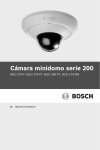
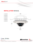
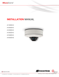
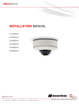
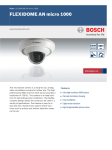
MicroDome Camera 200 Series
NDC-274-P, NDC-274-PT, NDC-284-PT, NCD-274-PM
en
Installation Manual
MicroDome Camera 200 Series
Table of Contents | en
3
Table of Contents
1
Safety
5
1.1
Safety precautions
5
1.2
Important safety instructions
6
1.3
FCC & ICES compliance
7
1.4
UL certification
8
1.5
Bosch notices
8
1.6
Copyrights
9
2
Introduction
2.1
Features
10
2.2
Unpacking
11
3
Installation
12
3.1
Disassembly
12
3.2
Memory card
13
3.3
Desiccant for rugged cameras
13
10
3.4
Network (and power) connector
14
3.5
Power connection
15
3.5.1
DC power connection
15
3.6
Mounting
16
3.7
Camera set-up
17
3.7.1
Camera positioning
18
3.8
Resetting the camera
19
3.9
Closing the unit
19
4
Browser connection
20
4.1
Protected network
20
5
Troubleshooting
21
5.1
Resolving problems
21
5.2
Customer service
22
6
Maintenance
23
6.1
Repairs
23
6.1.1
Transfer and disposal
23
Bosch Security Systems
Installation Manual
AR18-10-B012 | v1.55 | 2012.09
4
en | Table of Contents
MicroDome Camera 200 Series
7
Technical Data
24
7.1
Specifications
24
7.1.1
Accessories
26
AR18-10-B012 | v1.55 | 2012.09
Installation Manual
Bosch Security Systems
MicroDome Camera 200 Series
Safety | en
1
Safety
1.1
Safety precautions
5
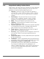
DANGER!
High risk: This symbol indicates an imminently hazardous
situation such as "Dangerous Voltage" inside the product.
If not avoided, this will result in an electrical shock, serious
bodily injury, or death.
WARNING!
Medium risk: Indicates a potentially hazardous situation.
If not avoided, this could result in minor or moderate bodily
injury.
CAUTION!
Low risk: Indicates a potentially hazardous situation.
If not avoided, this could result in property damage or risk of
damage to the device.
Bosch Security Systems
Installation Manual
AR18-10-B012 | v1.55 | 2012.09
6
en | Safety
1.2
MicroDome Camera 200 Series
Important safety instructions
Read, follow, and retain for future reference all of the following
safety instructions. Heed all warnings on the unit and in the
operating instructions before operating the unit.
1.
Cleaning - Generally, using a dry cloth for cleaning is
sufficient but a moist, fluff-free cloth or leather shammy
may also be used. Do not use liquid cleaners or aerosol
cleaners.
2.
Heat Sources - Do not install the unit near any heat
sources such as radiators, heaters, stoves, or other
equipment (including amplifiers) that produce heat.
3.
Water - Never spill liquid of any kind on the unit.
4.
Lightning - Take precautions to protect the unit from
power and lightning surges.
5.
Controls adjustment - Adjust only those controls specified
in the operating instructions. Improper adjustment of
other controls may cause damage to the unit.
6.
Power sources - Operate the unit only from the type of
power source indicated on the label.
7.
Servicing - Unless qualified, do not attempt to service this
unit yourself. Refer all servicing to qualified service
personnel.
8.
Replacement parts - Use only replacement parts specified
by the manufacturer.
9.
Installation - Install in accordance with the manufacturer's
instructions and in accordance with applicable local codes.
10. Attachments, changes or modifications - Only use
attachments/accessories specified by the manufacturer.
Any change or modification of the equipment, not
expressly approved by Bosch, could void the warranty or,
in the case of an authorization agreement, authority to
operate the equipment.
AR18-10-B012 | v1.55 | 2012.09
Installation Manual
Bosch Security Systems
MicroDome Camera 200 Series
1.3
Safety | en
7
FCC & ICES compliance
FCC & ICES Information
This equipment has been tested and found to comply with the
limits for a Class B digital device, pursuant to part 15 of the
FCC Rules. These limits are designed to provide reasonable
protection against harmful interference in a residential
installation. This equipment generates, uses, and can radiate
radio frequency energy and, if not installed and used in
accordance with the instructions, may cause harmful
interference to radio communications. However, there is no
guarantee that interference will not occur in a particular
installation. If this equipment does cause harmful interference
to radio or television reception, which can be determined by
turning the equipment off and on, the user is encouraged to try
to correct the interference by one or more of the following
measures:
–
reorient or relocate the receiving antenna;
–
increase the separation between the equipment and
receiver;
–
connect the equipment into an outlet on a circuit different
from that to which the receiver is connected;
–
consult the dealer or an experienced radio/TV technician
for help.
This device complies with part 15 of the FCC Rules. Operation
is subject to the following two conditions:
1.
this device may not cause harmful interference, and
2.
this device must accept any interference received,
including interference that may cause undesired operation.
Intentional or unintentional modifications, not expressly
approved by the party responsible for compliance, shall not be
made. Any such modifications could void the user's authority to
operate the equipment. If necessary, the user should consult
the dealer or an experienced radio/television technician for
corrective action.
Bosch Security Systems
Installation Manual
AR18-10-B012 | v1.55 | 2012.09
8
en | Safety
MicroDome Camera 200 Series
The user may find the following booklet, prepared by the
Federal Communications Commission, helpful: How to Identify
and Resolve Radio-TV Interference Problems. This booklet is
available from the U.S. Government Printing Office,
Washington, DC 20402, Stock No. 004-000-00345-4.
1.4
UL certification
Disclaimer
Underwriter Laboratories Inc. ("UL") has not tested the
performance or reliability of the security or signaling aspects of
this product. UL has only tested fire, shock and/or casualty
hazards as outlined in UL's Standard(s) for Safety for Closed
Circuit Television Equipment, UL 2044. UL Certification does not
cover the performance or reliability of the security or signaling
aspects of this product.
UL MAKES NO REPRESENTATIONS, WARRANTIES, OR
CERTIFICATIONS WHATSOEVER REGARDING THE
PERFORMANCE OR RELIABILITY OF ANY SECURITY OR
SIGNALING RELATED FUNCTIONS OF THIS PRODUCT.
1.5
Bosch notices
Disposal - Your Bosch product was developed and
manufactured with high-quality material and components that
can be recycled and reused. This symbol means that
electronic and electrical appliances, which have reached the
end of their working life, must be collected and disposed of
separately from household waste material. Separate collecting
systems are usually in place for disused electronic and
electrical products. Please dispose of these devices at an
environmentally compatible recycling facility, per European
Directive 2002/96/EC
More information
For more information please contact the nearest Bosch Security
Systems location or visit www.boschsecurity.com
AR18-10-B012 | v1.55 | 2012.09
Installation Manual
Bosch Security Systems
MicroDome Camera 200 Series
1.6
Safety | en
9
Copyrights
The firmware 4.1 uses the fonts "Adobe-Helvetica-Bold-RNormal--24-240-75-75-P-138-ISO10646-1" and "AdobeHelvetica-Bold-R-Normal--12-120-75-75-P-70-ISO10646-1" under
the following copyright:
Copyright 1984-1989, 1994 Adobe Systems Incorporated.
Copyright 1988, 1994 Digital Equipment Corporation.
Permission to use, copy, modify, distribute and sell this
software and its documentation for any purpose and without
fee is hereby granted, provided that the above copyright
notices appear in all copies and that both those copyright
notices and this permission notice appear in supporting
documentation, and that the names of Adobe Systems and
Digital Equipment Corporation not be used in advertising or
publicity pertaining to distribution of the software without
specific, written prior permission.
This software is based in part on the work of the Independent
JPEG Group.
Bosch Security Systems
Installation Manual
AR18-10-B012 | v1.55 | 2012.09
10
en | Introduction
MicroDome Camera 200 Series
2
Introduction
2.1
Features
This MicroDome camera is a ready-to-use, complete network
video surveillance system inside a compact camera. The camera
offers a cost-effective solution for a broad range of
applications. It uses H.264 compression technology to give
clear images reducing bandwidth and storage.The camera can
be used as a stand-alone video surveillance system with no
additional equipment or it can easily integrate with the Bosch
DVR 700 Series recorders.
Features include:
–
MicroSD/SDHC/SDXC card slot supports edge recording
up to 2 TB
–
Tri-streaming: Two H.264 streams and one M-JPEG stream
–
Progressive scan for sharp images of moving objects
–
Built-in microphone (NDC-274-P only)
–
Tamper, motion and audio detection
–
Conforms to the ONVIF standard for wide compatibility
–
Power over Ethernet (IEEE 802.3af compliant)
AR18-10-B012 | v1.55 | 2012.09
Installation Manual
Bosch Security Systems
MicroDome Camera 200 Series
2.2
Introduction | en
11
Unpacking
Unpack carefully and handle the equipment with care.
The packaging contains:
–
IP camera with lens
–
Installation paper sticker
–
Quick installation guide
–
Torx screwdriver for dome cover
–
Optical disk
–
Bosch Video Client
–
Documentation
–
Tools
If equipment has been damaged during shipment, repack it in
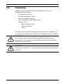
the original packaging and notify the shipping agent or supplier.
WARNING!
Installation should only be performed by qualified service
personnel in accordance with the National Electrical Code or
applicable local codes.
CAUTION!
The camera module is a sensitive device and must be handled
carefully.
Bosch Security Systems
Installation Manual
AR18-10-B012 | v1.55 | 2012.09
12
en | Installation
MicroDome Camera 200 Series
3
Installation
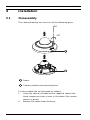
3.1
Disassembly
The camera/housing unit consists of the following parts:
x3
Dome
Camera module and mounting base
To disassemble the unit proceed as follows:
1.
Using the special screwdriver bit supplied, loosen the
three tamper-resistant screws in the dome (the screws
remain in place).
2.
Remove the dome from the base.
AR18-10-B012 | v1.55 | 2012.09
Installation Manual
Bosch Security Systems
MicroDome Camera 200 Series
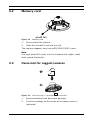
3.2
Installation | en
13
Memory card
Figure 3.1
Memory card
1.
Disassemble the camera.
2.
Slide the microSD card into the slot.
The camera supports most microSD/SDHC/SDXC cards.
Note:
Use high speed SD cards, class 6 or above (the higher read/
write speed the better).
3.3
Desiccant for rugged cameras
Figure 3.2
1.
2.
Desiccant for PT and PM camera versions.
Remove backing from desiccant package.
Stick the package to the inside of the dome cover as
indicated.
Bosch Security Systems
Installation Manual
AR18-10-B012 | v1.55 | 2012.09
14
en | Installation
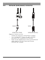
3.4
MicroDome Camera 200 Series
Network (and power) connector
RJ45
M12
Ethernet (PoE)
Ethernet (PoE)
Figure 3.3
Network connection
–
Connect the camera to a 10/100 Base-T network.
–
Use a shielded UTP Category 5e cable with RJ45
–
Power can be supplied to the camera via the Ethernet
connectors (M12 connector for PM version).
cable compliant with the Power-over-Ethernet
(IEEE 802.3af) standard.
AR18-10-B012 | v1.55 | 2012.09
Installation Manual
Bosch Security Systems
MicroDome Camera 200 Series
3.5
Installation | en
15
Power connection
The camera can accept power from both the DC12/24V power
input and the Ethernet input at the same time. (Changing the
power source might lead to a camera reboot.)
3.5.1
DC power connection
(Not present on NDC-274-PM version.)
5 mm
(0.2 in)
22AWG
12 VDC
24 VDC
Figure 3.4
1.
DC power connection
Slide the plug adapter that matches your outlet socket
onto the supplied power supply.
2.
Insert the power connector jack from the power supply
into the DC12/24V socket of the camera.
3.
Connect the power supply to either a 230 VAC or a
120 VAC power supply outlet.
Note:
A power supply is not included in the package.
Bosch Security Systems
Installation Manual
AR18-10-B012 | v1.55 | 2012.09
16
en | Installation
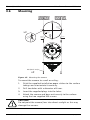
3.6
MicroDome Camera 200 Series
Mounting
0~
FRONT
Inner 2.5mm 2 Holes
(M3 TYPE SCREW)
270°
x2
90°
Outer
6.0mm 2 Holes
(FOR PLASTIC ANCHOR)
m
m
CABLE
Ø
6
CAMERA
OUTLINE
CUT LINE
180°
M3 (Ø2.5 mm)
x2
Figure 3.5
Mounting the camera
To mount the camera to a wall or ceiling:
1.
Stick the supplied installation paper sticker to the surface
taking care to orientate it correctly.
2.
Drill two holes with a diameter of 6 mm.
3.
Insert the supplied plugs into the holes.
4.
Attach the camera and base unit securly to the surface
using the two supplied M3 screws.
CAUTION!
Do not point the camera/lens into direct sunlight as this may
damage the sensors.
AR18-10-B012 | v1.55 | 2012.09
Installation Manual
Bosch Security Systems
MicroDome Camera 200 Series
3.7
Installation | en
17
Camera set-up
To help set up the camera, connect a monitor to the miniature
2.5 mm jack socket using a S1460 monitor cable which can be
ordered separately. This monitor jack socket provides a
composite video signal (NTSC) for installation purposes only.
S1460 Monitor Cable
Bosch Security Systems
Installation Manual
AR18-10-B012 | v1.55 | 2012.09
18
en | Installation
3.7.1
MicroDome Camera 200 Series
Camera positioning
The camera module position can be adjusted along two axes.
When adjusting the camera position ensure that the picture
display on the monitor is level.
CAUTION!
The image sensors are highly sensitive and require special care
for proper performance and extended lifetime. Do not expose
them to direct sunlight or bright spotlights in operating and
non-operating conditions. Avoid bright lights in the field of view
of the camera.
Set the camera to the desired position by performing the
following steps:
1.
For horizontal adjustment (pan) rotate the camera module
2.
For vertical adjustment (tilt) rotate camera. Do not rotate
in the base. Do not rotate more than 350°.
more than 55°.
AR18-10-B012 | v1.55 | 2012.09
Installation Manual
Bosch Security Systems
MicroDome Camera 200 Series
3.8
Installation | en
19
Resetting the camera
If the camera cannot be connected because the IP address has
changed, press and hold the reset button (7 seconds
approximately) to recall the factory default values. The factory
default IP address is 192.168.0.1
Figure 3.6
3.9
Reset button
Closing the unit
When the camera position is set and all adjustments have been
made, close the unit.
1.
Remove the monitor cable from the jack socket.
2.
If necessary, clean the inner surface of the dome with a
soft cloth.
3.
Position the dome on the base by aligning the two screw
holders with fins with the openings beside the screw
sockets and slot it home.
4.
Use the supplied special screwdriver bit to tighten the
three tamper-resistant screws.
Bosch Security Systems
Installation Manual
AR18-10-B012 | v1.55 | 2012.09
20
en | Browser connection
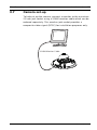
4
MicroDome Camera 200 Series
Browser connection
A computer with Microsoft Internet Explorer can be used to
receive live images from the camera, control the camera, and
replay stored sequences. The camera is configured over the
network using the browser.
Note:
The camera can also be configured using the supplied Bosch
Video Client or the Bosch Video Management System.
4.1
Protected network
If a RADIUS server is used for network access control (802.1x
authentication), the camera must be configured first. To
configure the camera for a Radius network, connect it directly
to a PC via a crossed network cable and configure the two
parameters, Identity and Password. Only after these have been
configured can communication with the camera via the network
occur.
AR18-10-B012 | v1.55 | 2012.09
Installation Manual
Bosch Security Systems
MicroDome Camera 200 Series
Troubleshooting | en
5
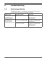
Troubleshooting
5.1
Resolving problems
21
The following table is intended to help identify the causes of
malfunctions and correct them when possible.
Malfunction
Possible causes
Solution
No image
Faulty cable connections. Check all cables, plugs,
transmission to
contacts and
remote location.
connections.
No connection
The unit's configuration.
Check all configuration
established, no
parameters.
image transmission. Faulty installation.
Check all cables, plugs,
contacts and
connections.
Bosch Security Systems
Installation Manual
AR18-10-B012 | v1.55 | 2012.09
22
en | Troubleshooting
5.2
MicroDome Camera 200 Series
Customer service
If a fault cannot be resolved, please contact your supplier or
system integrator, or contact Bosch Security Systems
Customer Service directly.
The Installer should write down all information regarding the
unit so that it can be referenced for warranty or repair. The
version numbers of the firmware and other status information
can be seen when the unit starts or by opening the Service
menu. Note down this information and the information found
on the camera label before contacting customer service.
AR18-10-B012 | v1.55 | 2012.09
Installation Manual
Bosch Security Systems
MicroDome Camera 200 Series
Maintenance | en
6
Maintenance
6.1
Repairs
23
CAUTION!
Never open the casing of the camera. The unit does not contain
any user serviceable parts. Ensure that all maintenance or
repair work is performed only by qualified personnel (electrical
engineering or network technology specialists). If in doubt,
contact your dealer's technical service center.
6.1.1
Transfer and disposal
The camera should only be passed-on together with this
installation guide. The unit contains environmentally hazardous
materials that must be disposed of according to law. Defective
or superfluous devices and parts should be disposed of
professionally or taken to your local collection point for
hazardous materials.
Bosch Security Systems
Installation Manual
AR18-10-B012 | v1.55 | 2012.09
24
en | Technical Data
MicroDome Camera 200 Series
7
Technical Data
7.1
Specifications
Input voltage
+12 VDC, +24 VDC, or Power-over-Ethernet
Power consumption
3.84 W (max)
Sensor type
1/2.7-inch CMOS
1/3.2-inch CMOS (NDC-284-PT)
Sensor pixels
1920 x 1080
2592 x 1944 (NDC-284-PT)
Sensitivity
0.3 lx
Video resolution
1080p, 720p, 480p, 240p
5 Megapixels, 480p (NDC-284-PT)
Video compression
H.264 MP (Main Profile);
M-JPEG
Max. frame rate
30 fps
12 fps (NDC-284-PT)
(M-JPEG frame rate can vary depending on
system loading)
Lens type
4.37 mm fixed, F2.0
3.74 mm fixed, F2.0 (NDC-284-PT)
Audio Input
Built-in microphone (NDC-274-P only)
Audio compression
G.711, L16 (live and recording)
Analogue video out
2.5 mm jack for installation only (NTSC)
(not for NDC-274-PM)
AR18-10-B012 | v1.55 | 2012.09
Installation Manual
Bosch Security Systems
MicroDome Camera 200 Series
Memory card slot
Technical Data | en
25
Supports up to 32 GB microSDHC / 2 TB
microSDXC card
(An SD card of Class 6 or higher is recommended
for HD recording)
Recording
Continuous recording, ring recording. alarm/
events/schedule recording
Unit Configuration
Via web browser or PC surveillance software
Protocols
IPv4, IPv6, UDP, TCP, HTTP, HTTPS, RTP,
IGMPV2/V3, ICMP, RTSP, FTP, Telnet, ARP, DHCP,
SNTP,SNMP (V1, MIB-II), 802.1x, SMTP, iSCSI,
UPnP(SSDP)
Encryption
TLS 1.0, SSL
Ethernet
10/100 Base-T, auto-sensing, half/full duplex
Ethernet connector
RJ45
M12 D-coded female (NDC-274-PM)
PoE
IEEE 802.3af compliant
Dimensions
Diameter: 105 mm (4.13 in)
(NDC-274-P)
Height: 56 mm (2.2 in)
Weight
255 g (8.99 oz) approx.
(NDC-274-P)
Dimensions
Diameter: 110 mm (4.33 in)
Height: 55 mm (2.17 in)
Weight
330 g (11.64 oz) approx.
IP protection
IP66 (PT and PM versions only)
Impact protection
IK08 (PT and PM versions only)
Operating
-20 ºC to +50 ºC (-4 ºF to +122 ºF)
Temperature
Bosch Security Systems
Installation Manual
AR18-10-B012 | v1.55 | 2012.09
26
en | Technical Data
Storage
MicroDome Camera 200 Series
-20 ºC to +70 ºC (-4 ºF to +158 ºF)
Temperature
Humidity
7.1.1
10% to 80% relative humidity (non-condensing)
Accessories
Contact a Bosch representative in your area for the latest
available accessories or visit our website at
www.boschsecurity.com
AR18-10-B012 | v1.55 | 2012.09
Installation Manual
Bosch Security Systems
Bosch Security Systems
www.boschsecurity.com
© Bosch Security Systems, 2012