1
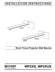
INSTALLATION INSTRUCTIONS
Instrucciones de instalación
Installationsanleitung
Instruções de Instalação
Istruzioni di installazione
Installatie-instructies
Instructions d´installation
WP2XS
WP2XUS
Short Throw Projector Wall Mounts
Spanish Product Description
German Product Description
Portuguese Product Description
Italian Product Description
Dutch Product Description
French Product Description
WP2XS, WP2XUS
WP2XS, WP2XUS
Installation Instructions
DISCLAIMER
Milestone AV Technologies and its affiliated corporations and
subsidiaries (collectively "Milestone"), intend to make this
manual accurate and complete. However, Milestone makes no
claim that the information contained herein covers all details,
conditions or variations, nor does it provide for every possible
contingency in connection with the installation or use of this
product. The information contained in this document is subject
to change without notice or obligation of any kind. Milestone
makes no representation of warranty, expressed or implied,
regarding the information contained herein. Milestone assumes
no responsibility for accuracy, completeness or sufficiency of
the information contained in this document.
Chief® is a registered trademark of Milestone AV Technologies.
All rights reserved.
WARNING: Never operate this mounting system if it is
damaged. Return the mounting system to a service center for
examination and repair.
WARNING: Do not use this product outdoors.
IMPORTANT ! : The WP2XS and WP2XUS mounts are
designed to be mounted to:
•
•
•
•
•
an 8" concrete wall;
an 8"x 8"x16" concrete block wall;
a clay brick wall;
a 2" x 4" wood studs (16" on center); or
a 2" x 4"-25ga minimum steel studs wall.
WP2XS models do not include UL Listed RSA series product
and are considered accessories.
IMPORTANT WARNINGS AND
CAUTIONS!
--SAVE THESE INSTRUCTIONS-WARNING: A WARNING alerts you to the possibility of
serious injury or death if you do not follow the instructions.
CAUTION: A CAUTION alerts you to the possibility of
damage or destruction of equipment if you do not follow the
corresponding instructions.
WARNING: Failure to read, thoroughly understand, and
follow all instructions can result in serious personal injury,
damage to equipment, or voiding of factory warranty! It is the
installer’s responsibility to make sure all components are
properly assembled and installed using the instructions
provided.
WARNING: Failure to provide adequate structural strength
for this component can result in serious personal injury or
damage to equipment! It is the installer’s responsibility to
make sure the structure to which this component is attached
can support five times the combined weight of all equipment.
Reinforce the structure as required before installing the
component. The wall to which the mount is being attached
may have a maximum drywall thickness of 5/8" (1.6cm) for
wood stud installation, and 1/2" (1.3cm) for steel stud
installation.
WARNING: Exceeding the weight capacity can result in
serious personal injury or damage to equipment! It is the
installer’s responsibility to make sure the weight of the
projector does not exceed 25 lbs (11.3 kg).
WARNING: Use this mounting system only for its intended
use as described in these instructions. Do not use
attachments not recommended by the manufacturer.
2
Installation Instructions
WP2XS, WP2XUS
DIMENSIONS
WP21S/US
WP22S/US
DIMENSION A
24.36 [618.8]
40.36 [1025.2]
DIMENSION B MIN DIMENSION B MAX WEIGHT CAPACITY
3.62 [92.0]
22.12 [561.9]
25 LBS
WP21S/US
8.62
219.0
1.00
25.4
B
1-1/2" PIPE THREAD
ATTACH PROJECTOR MOUNT HERE
DIMENSIONS:
INCHES
[MILLIMETERS]
3
WP2XS, WP2XUS
Installation Instructions
LEGEND
4
Tighten Fastener
Pencil Mark
Apretar elemento de fijación
Marcar con lápiz
Befestigungsteil festziehen
Stiftmarkierung
Apertar fixador
Marcar com lápis
Serrare il fissaggio
Segno a matita
Bevestiging vastdraaien
Potloodmerkteken
Serrez les fixations
Marquage au crayon
Loosen Fastener
Drill Hole
Aflojar elemento de fijación
Perforar
Befestigungsteil lösen
Bohrloch
Desapertar fixador
Fazer furo
Allentare il fissaggio
Praticare un foro
Bevestiging losdraaien
Gat boren
Desserrez les fixations
Percez un trou
Phillips Screwdriver
Adjust
Destornillador Phillips
Ajustar
Kreuzschlitzschraubendreher
Einstellen
Chave de fendas Phillips
Ajustar
Cacciavite a stella
Regolare
Kruiskopschroevendraaier
Afstellen
Tournevis à pointe cruciforme
Ajuster
Open-Ended Wrench
Remove
Llave de boca
Quitar
Gabelschlüssel
Entfernen
Chave de bocas
Remover
Chiave a punte aperte
Rimuovere
Steeksleutel
Verwijderen
Clé à fourche
Retirez
By Hand
Optional
A mano
Opcional
Von Hand
Optional
Com a mão
Opcional
A mano
Opzionale
Met de hand
Optie
À la main
En option
Hex-Head Wrench
Security Wrench
Llave de cabeza hexagonal
Llave de seguridad
Sechskantschlüssel
Sicherheitsschlüssel
Chave de cabeça sextavada
Chave de segurança
Chiave esagonale
Chiave di sicurezza
Zeskantsleutel
Veiligheidssleutel
Clé à tête hexagonale
Clé de sécurité
Installation Instructions
WP2XS, WP2XUS
TOOLS REQUIRED FOR INSTALLATION
5/32"
5/32" (security)
(included)
1/4" (included)
Hardware required, not included:
Steel Stud Install
4 - Toggler® 1/4-20 (BB) Snap-Toggle
4 - Grade 2 or better 1/4-20 x 1-3/4" Phillips
pan head screws
4 - Grade 2 or better 1/4" washer
1/2"
3/8"
PARTS
A (1)
[Projector arm]
B (1)
[Wall plate
cover - left]
OR
C (1)
[Wall plate
cover - right]
(WP21S shown)
ALL
MODELS
D (1)
[End cap]
(WP21US shown)
J (8)
M5 x 12mm
H (1)
M5 x 35mm
F (4)
5/16"
E (1)
[Wall plate]
L (1)
5/32"
(security)
N (1)
M (4)
5/16-18 x 1/2"
10-24 x 3/8"
(security)
(security)
P (2)
10-24 x 3/8"
WP2XUS
MODELS
ONLY
All-Points
Security
Kit Card
W (1)
[SSB cover]
G (4)
5/16" x 2-1/2"
Q (4)
M3x25mm
K (4)
[Anchor]
R (4)
M4x25mm
AB (4)
M2.5x10mm
AE (4)
8-32 x 3/8"
X (1)
[Base plate]
V (4)
[Thumb
nuts]
U (4)
.500x.257x.625
T (4)
M6x25mm
AA (4)
8-32 x 1/4"
S (4)
M5x25mm
AC (4)
M3x10mm
AF (4)
M5x14mm
AD (4)
M4x10mm
AG (4)
M6x14mm
AI (4)
M4
AH (4)
1/4-20
Y (4)
[SSB leg]
AJ (1)
1/4"
AK (1)
5/32"
(security)
5
WP2XS, WP2XUS
Installation Instructions
INSTALLATION
The WP2XS/WP2XUS short throw projector mounts are
designed to be mounted to an 8" concrete, 8"x8"x16" concrete
block, clay brick, 2" x 4" wood studs (16" on center), or steel
studs wall.
2
x4
NOTE: Proceed to the Concrete, Concrete Block or Clay
3
Brick, Wood Studs or Steel Studs Installation
Installation section, as appropriate for installation.
(F)
Concrete, Concrete Block or Clay Brick
Installation
1.
Determine mounting location on wall.
2.
Using wall plate (E) as a template, mark four holes through
mounting holes in wall plate. (See Figure 1)
3.
Drill four 3/8" holes at marked locations in wall. (See Figure 1)
4.
Install four anchors (K) into drilled holes. (See Figure 1)
5.
Install four 5/16 x 2-1/2" hex head lag screws (G) through
four 5/16" washers (F), holes in wall plate (E) and into four
anchors (K). (See Figure 1)
(E)
4
(G) x 4
NOTE: Proceed to Install Short Throw Projector Arm to
Wall Plate section to continue installation.
Figure 2
NOTE: Proceed to Install Short Throw Projector Arm to
Wall Plate section to continue installation.
2
x4
3
Steel Studs Installation
(E)
WARNING: IMPROPER INSTALLATION CAN LEAD TO
EQUIPMENT FALLING CAUSING SERIOUS PERSONAL
INJURY OR DAMAGE TO EQUIPMENT! The following figure
identifies the minimum requirements for installation of mount
onto a steel stud structure. If the structure or its components
do not meet these requirements contact the mount
manufacturer for specific instructions before attempting
installation. It should also be noted that no other equipment
should be mounted to the same stud. (See Figure 3)
(F) x 4
5
(G) x 4
4
(K) x 4
Figure 1
Wood Studs Installation
1.
Determine mounting location on wall. Use a stud finder to
locate studs.
2.
Using wall plate (E) as a template, mark four holes through
mounting holes in wall plate. (See Figure 2)
3.
Drill four 7/32" holes at marked locations in wall. (See
Figure 2)
4.
Install four 5/16 x 2-1/2" hex head lag screws (G) through
four 5/16" washers (F), holes in wall plate (E) and into four
pilot holes. (See Figure 2)
6
Installation Instructions
WP2XS, WP2XUS
Site Requirements
16" (on center) Studs
Short Throw Mount Installation Location
(Must be centered over two studs)
If back side of wall is unfinished, drywall must be installed
to a minimum of one stud left and right of the studs
being used to install the mount. Drywall must be
secured to studs with screws 12" on center
There must be a minimum of
1-7/8" (48mm) clearance
inside wall
FRONT
Drywall
**1/2" minimum
Drywall Thickness
(Both Sides of Stud)
**See hazard statement
on page 2!
Steel Stud (2 x 4 / 25ga minimum)
Stud type and structural strength must conform to the North American
Specification for the Design of Cold-Formed Steel Structural Members.
[362, 125 18, C-Shape, S - Stud Section]
Figure 3
7
WP2XS, WP2XUS
Installation Instructions
Steel Studs
Steel Stud
IMPORTANT ! : See Site Requirements section before
proceeding with Steel Studs installation to ensure
installation site meets requirements! The drywall must
have a minimum thickness of 1/2"!
1.
Determine mounting location on wall. Use stud finder to
locate steel studs.
2.
Line up four holes on wall plate (E) with center of studs at
desired mounting location. (See Figure 4)
3.
Using wall plate as a template, mark four holes at the four
holes in wall plate. (See Figure 4)
4.
Drywall
Plastic Cap
6
7
anchor x 4
Drill four 1/2" holes at marked locations on wall. (See
Figure 4)
Anchor Metal Channel
(side view)
(E)
Figure 6
8.
Snap off plastic straps on anchor at wall by pushing side to
side, snapping off straps level with flange of plastic cap.
(See Figure 7)
9.
Repeat Steps 6 through 8 for each mounting hole.
Steel Stud
Drywall
Plastic Cap
8
3
x4
4
Plastic Straps
Figure 4
5.
Anchor Metal Channel
Hold metal channel on Toggler® 1/4-20 (BB) Snap-Toggle
(not included) flat alongside plastic straps and slide channel
through hole. (See Figure 5)
Drywall
Plastic Straps
5
x4
Figure 5
6.
Holding plastic straps on anchor, pull anchor away from wall
until channel rests flush behind wall making sure anchor
channel is positioned vertically on stud. (See Figure 6)
7.
Slide plastic cap on anchor towards wall until flange of cap
is flush with wall. (See Figure 6)
8
(side view)
Figure 7
Installation Instructions
WP2XS, WP2XUS
10. Place wall plate (E) over anchors and align mounting holes
in wall plate with holes in anchors. (See Figure 8)
11. Insert Grade 2 or better 1/4-20 x 1-3/4" Phillips pan head
screws (not included) through Grade 2 or better 1/4" washer
(not included), corresponding mounting hole on wall bracket
and into Snap-Toggle (not included) and tighten until flush
against mount. DO NOT overtighten! (See Figure 8)
12. Repeat Steps 10 and 11 for remaining 3 mounting holes.
(A)
Tab
WARNING: IMPROPER INSTALLATION CAN LEAD TO
EQUIPMENT FALLING CAUSING SERIOUS PERSONAL
INJURY OR DAMAGE TO EQUIPMENT! Overtightening of
mounting hardware can damage the steel studs. DO NOT
overtighten mounting hardware!
1
Steel Stud
Drywall
Slot
x4
11
(E)
x4
2
(J) x 4
Figure 9
3.
Insert and slightly tighten one M5 x 35mm Phillips head cap
screw (H) into wall plate (E). (See Figure 10)
(E)
(E)
Anchor Metal Channel
(side view)
Figure 8
Installing Short Throw Projector Arm to Wall
Plate
1.
Lower projector arm (A) onto wall plate (E), ensuring that
tabs on projector arm slide into slots on wall plate. (See
Figure 9)
2.
Fasten projector arm (A) to wall plate (E) using four
M4 x 12mm Phillips head cap screws (J). (See Figure 9)
3
(H) x 1
Figure 10
9
WP2XS, WP2XUS
Installation Instructions
NOTE: Proceed to Adjustments section to continue
Projector Installation (WP2XUS Models Only)
installation.
WARNING: Exceeding the weight capacity can result in
serious personal injury or damage to equipment! It is the
installer’s responsibility to make sure the weight of the
projector does not exceed 25 lbs (11.3 kg).
1.
(A)
Assemble and attach SSBU (W, X and Y) to projector
following instructions included with SSBU.
Mounting
slots
NOTE: SSBU bracket may also be installed using the optional
All-Points Security Kit (L-P).
WARNING: IMPROPER INSTALLATION CAN LEAD TO
PROJECTOR FALLING RESULTING IN SERIOUS
PERSONAL INJURY OR DAMAGE TO EQUIPMENT.
Ensure that mounting slots in mount base slide under thumb
screws and that screws are seated in the back of slots.
2.
Orient projector with attached SSBU bracket so that front of
projector faces wall. (See Figure 11)
3.
Lift projector so that screws with thumb nuts (V) in SSBU
are aligned with mounting slots in projector arm base. (See
Figure 11)
4.
Slide projector with SSBU bracket onto mounting slots in
projector arm base until screws are seated against the back
of mounting slots. (See Figure 11)
5.
Turn thumb nuts until tight to secure projector to projector
arm. (See Figure 12)
6.
Tighten the M5x35mm button head cap screw (H) on the
wall plate (E). (See Figure 12)
4
2
3
Front of
projector
(W, X, Y)
Figure 11
(E)
(A)
6
(H) x 1
5
Figure 12
10
Mounting
slots
(V)
Installation Instructions
WP2XS, WP2XUS
7.
Projector Installation (WP2XS Models Only)
Tighten the M5x35mm button head cap screw (H) on the
wall plate (E). (See Figure 14)
WARNING: Exceeding the weight capacity can result in
serious personal injury or damage to equipment! It is the
installer’s responsibility to make sure the weight of the
projector does not exceed 25 lbs (11.3 kg).
1.
2.
(A)
Assemble and attach UL Listed RSA Series product (not
included) to short throw projector arm threaded end
following instructions included with RSA.
Mounting
slots
Attach required interface bracket (not included) to projector
following instructions included with interface bracket.
5
WARNING: IMPROPER INSTALLATION CAN LEAD TO
PROJECTOR FALLING RESULTING IN SERIOUS
PERSONAL INJURY OR DAMAGE TO EQUIPMENT.
Ensure that mounting slots in RSA slide under thumb screws
and that screws are seated in the back of slots.
3.
Orient projector with attached bracket so that front of
projector lines up with front of projector arm. (See Figure 13)
4.
Lift projector so that screws with thumb nuts (V) in interface
bracket are aligned with mounting slots in projector arm
base. (See Figure 13)
5.
Slide projector with interface bracket onto mounting slots in
projector arm base until screws are seated against the back
of mounting slots. (See Figure 13)
6.
Turn thumb nuts until tight to secure projector to projector
arm. (See Figure 14)
3
Mounting
slots
4
Front of
projector
Interface
bracket (not included)
Figure 13
(E)
(A)
7
(H) x 1
6
(V)
Figure 14
11
WP2XS, WP2XUS
Installation Instructions
Adjustments
Projector Arm Height Adjustment
Distance from Wall / Screen Size (See Figure 15)
13. Loosen two Phillips screws (one on left, one on right) on
sides of projector arm plate. (See Figure 16)
1.
Loosen two Phillips screws (one on left, one on right).
2.
Slide the RSA mount along the projector arm (A), as
required.
3.
Tighten two Phillips screws.
Yaw Adjustment (See Figure 15)
4.
Loosen yaw adjustment screw using a 5/32" hex key.
14. Adjust the angle of the projector arm to counteract the
projector weight.
•
Turn counterclockwise to lower projector arm angle.
•
Turn clockwise to raise projector arm angle.
15. Tighten two Phillips screws (one on left, one on right) on
sides of projector arm plate. (See Figure 16)
WARNING: Do NOT turn the RSA to the end of the pipe
threads. The projector, interface bracket and RSA will fall
from the pipe if it is unthreaded too far!
5.
Adjust projector by turning the RSA on the pipe to the
desired position.
6.
Tighten yaw adjustment locking screw using a 5/32" hex
key.
14
OR
Pitch Adjustment (See Figure 15)
NOTE: Use a level to make this process easier.
7.
Loosen two Phillips screws (one on right, one on left).
8.
Tip up or down, as required.
9.
Tighten two Phillips screws.
Roll Adjustment (See Figure 15)
NOTE: Use a level to make this process easier.
10. Loosen one Phillips screw.
13
15
11. Adjust horizontal tilt, as required.
Figure 16
12. Tighten one Phillips screw.
1
2
(A)
3
x2
Cable Management (Optional)
1.
Route cables/cords from projector through opening on
projector arm and route to wall. (See Figure 17)
2.
Guide cables/cords from wall end of projector arm
downward through slots in wall plate. (See Figure 17)
Cable management
covers
(RSA
mount)
2
1
x2
7
8
OR
x1
9
4
5
6
Cable
(examples)
2
x1
10
11
12
Figure 15
12
(SSBU and
projector not shown)
Figure 17
Installation Instructions
WP2XS, WP2XUS
Add Covers
1.
Add left and right wall plate covers (B and C) over wall plate
(E). (See Figure 18)
2.
Fasten covers using four M5 x 12mm Phillips cap head
screws (J). (See Figure 18)
(J) x 2
2
1
(E)
(C)
(B)
1
(J) x 2
2
Figure 18
3.
Add end cap (D) to end of short throw projector arm (A).
(See Figure 19)
(A)
(D)
3
(projector not shown)
Figure 19
13
WP2XS, WP2XUS
14
Installation Instructions
Installation Instructions
WP2XS, WP2XUS
15
WP2XS, WP2XUS
Installation Instructions
USA/International
Europe
Chief Manufacturing, a products division
of Milestone AV Technologies
8800-002102 Rev03
2012 Milestone AV Technologies, a
Duchossois Group Company
www.chiefmfg.com
12/12
Asia Pacific
A
P
F
A
P
F
A
6436 City West Parkway, Eden Prairie, MN 55344
800.582.6480 / 952.225.6000
877.894.6918 / 952.894.6918
Franklinstraat 14, 6003 DK Weert, Netherlands
+31 (0) 495 580 852
+31 (0) 495 580 845
Office No. 1 on 12/F, Shatin Galleria
18-24 Shan Mei Street
Fotan, Shatin, Hong Kong
P 852 2145 4099
F 852 2145 4477