1
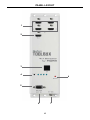
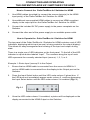
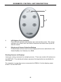
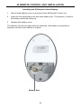
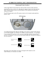
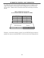
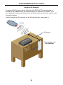
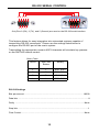
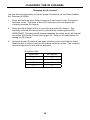
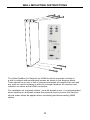
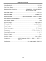
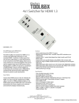
Gefen
4x1 Switcher
for HDMI®
GTB-MHDMI1.3-441
GTB-MHDMI1.3-441-BLK
User Manual
www.gefentoolbox.com
ASKING FOR ASSISTANCE
Technical Support:
Telephone
Fax
(818) 772-9100
(800) 545-6900
(818) 772-9120
Technical Support Hours:
8:00 AM to 5:00 PM Monday thru Friday, Pacific Time
Write To:
Gefen, LLC.
c/o Customer Service
20600 Nordhoff St
Chatsworth, CA 91311
www.gefentoolbox.com
[email protected]
Notice
Gefen, LLC reserves the right to make changes in the hardware, packaging and
any accompanying documentation without prior written notice.
4x1 Switcher for HDMI is a trademark of Gefen, LLC
HDMI, the
logo, and High-Definition Multimedia Interface are
trademarks or registered trademarks of HDMI Licensing in the United States and
other countries.
© 2010 Gefen, LLC, All Rights Reserved
All trademarks are the property of their respective owners
Rev A6
1.2
CONTENTS
1
Introduction
2
Operation Notes
3
Features
4
Panel Layout
5
Panel Descriptions
6
Connecting & Operating The GefenToolBox 4x1 Switcher for HDMI
6
Connecting the GefenToolBox 4x1 Switcher for HDMI
6
How to Operate the GefenToolBox 4x1 Switcher for HDMI
7
Automatic Switching
8
IR Remote Control Unit Description
9
IR Remote Control Unit Installation
10 IR Remote Control Unit Configuration
11 IR Remote Control Unit Operation
12 IR Extender Installation
13 RS-232 Serial Control
13
Settings
14
Commands
16 Changing the IR Channel
17 Wall Mounting Instructions
18 Specifications
19 Warranty
INTRODUCTION
Congratulations on your purchase of the GefenToolBox 4x1 Switcher for HDMI.
Your complete satisfaction is very important to us.
About Gefen
We specialize in total integration for your home theater, while also focusing on
going above and beyond customer expectations to ensure you get the most from
your hardware. We invite you to explore our distinct product line. Please visit
http://www.gefen.com for the latest offerings in High-Definition signal solutions
or call us between the hours of 8:00 am and 5:00 pm Monday-Friday, Pacific
Standard Time for assistance with your A/V needs. We’ll be happy to assist you.
Why GefenToolBox?
The GefenToolBox line offers portable and easy-to-install solutions for common
A/V system integration setups using HDMI connectivity. GefenToolBox products
are wall-mountable and small in size. GefenToolBox products are easily
transported in the field and are ready for immediate and simple installations in
working environments. These products come finished in a glossy color to blend in
with either a white or black color scheme.
The GefenToolBox 4x1 Switcher for HDMI
The GefenToolBox 4x1 Switcher for HDMI routes high definition video at
resolutions up to 1080p@60Hz with multichannel digital audio from any four
Hi-Def sources to one displays. The GefenToolBox 4x1 Switcher eliminates the
need to disconnect and reconnect HDMI devices. It works with any HDMI source
that connects to an HDMI display, supporting advanced digital audio formats
such as Dolby TrueHD and DTS-HD Master Audio. Each source is accessible at
all times by selecting it with the included remote, the RS-232 port, or front panel
button.
How It Works
Connect the Hi-Def sources to the GefenToolBox 4x1 Switcher’s inputs using
the supplied HDMI cables. Connect the HDMI output to the display using HDMI
cables. 3D content can be displayed when connecting a 3DTV and 3D source.
Any of the four A/V sources may now be selected by using the front panel buttons, RS-232, or the included IR remote control.
1
OPERATION NOTES
READ THESE NOTES BEFORE INSTALLING OR
OPERATING THE GEFENTOOLBOX 4X1 SWITCHER FOR HDMI
•
The GefenToolBox 4x1 Switcher for HDMI has an Automatic Switching
feature: Each time a connected device is powered ON, GefenToolBox 4x1
Switcher for HDMI will switch to that input. Once the connected device is
powered down, the product will switch to the last active input. Switching can
always be managed through IR remote control, RS-232, and the front panel
buttons. See page 7 for details.
2
FEATURES
HDMI 1.3 Features
•
•
•
•
•
225 MHz (up to 12 bit YUV 444 @ 1080p)
Deep Color
Dolby TrueHD and DTS-HD Master Audio
Lip Sync
CEC Pass-Through
General Features
•
Switch between four (4) HDMI 1.3 sources without signal loss.
•
Maintains beautiful, sharp HDTV resolutions up to 1080p@60 Hz and
1920x1200@60Hz.
•
Supports 3DTV pass-through
•
Supports digital audio formats including LPCM 7.1, Dolby Digital Plus, Dolby
TrueHD, and DTS-HD Master Audio.
•
Supports the use of DVI sources and DVI displays with an HDMI-to-DVI
converter cable or adapter.
•
Input and output cables up to 15 feet in length can be used when using 8-bit
or 12-bit color. Extension distance is dependent upon the quality of the
cables being used.
•
This product is HDMI-compliant and HDCP-compliant.
Package Includes
(1)
(4)
(1)
(1)
(1)
GefenToolBox 4x1 Switcher for HDMI
6 ft HDMI cable (M-M)
5V DC Locking Power Supply
IR Remote Control Unit
User Manual
3
PANEL LAYOUT
1
2
3
4
8
5
6
7
4
PANEL DESCRIPTIONS
1
HDMI Input Ports 1-4
Connect HDMI-compliant source device(s) to any of these input ports.
2
HDMI Output Port
Connect an HDMI-compliant display device to this output port.
3
IR Window
Receives IR commands from the included IR remote (EXT-RMT-4IR), shown on
page 8.
4
Source Selector and Indicator LEDs
The black button labeled “Input” selects the input source (1-4) to be routed to the
display connected to the HDMI Output Port.
5
RS-232C Interface for Remote Control via Serial Communications
The GefenToolBox 4x1 Switcher for HDMI may be switched remotely using
serial communications with any office computer or a control automation device.
See page 13 for details.
6
3.5mm mini-Stereo jack for connecting Optional IR Extender
An optional IR Extender (sold separately) allows relocation of the IR sensor
(eye) up to 6 feet away from the GefenToolBox 4x1 Switcher, enabling
streamlined installations whereby the Switcher may be hidden away behind
furniture / behind the scenes. The IR Remote need only point at the extended IR
sensor to control the Switcher. Please see page 12 for a diagram.
7
5V DC Power Receptacle
Connect the included 5V DC power supply here and at a free wall outlet. Only
use the power supply supplied. Screw the locking power tip into the socket until
it fits snugly without overtightening.
8
5V Power Indicator LED (Red)
This LED will glow red once the included 5V DC power supply has been
properly connected to the unit and a power source.
5
CONNECTING AND OPERATING
THE GEFENTOOLBOX 4X1 SWITCHER FOR HDMI
How to Connect the GefenToolBox 4x1 Switcher for HDMI
1.
Use HDMI cables (provided) to connect the source device(s) to the HDMI
input port(s) of the GefenToolBox 4x1 Switcher for HDMI.
2.
Use additional user-supplied HDMI cables to connect an HDMI-compliant
display to the output port on the GefenToolBox 4x1 Switcher for HDMI.
3.
Connect the included 5V DC power supply to the power receptacle on the
Switcher.
4.
Connect the other end of the power supply to an available power outlet.
How to Operate the GefenToolBox 4x1 Switcher for HDMI
The top panel of the GefenToolBox 4x1 Switcher for HDMI contains a set of LED
indicators, displaying which input (source) is being routed to the output (display).
This allows for easy management and viewing of the input and output routing
state.
There is a single row of LED indicators on the front panel. To the left of the LED
indicator is a push button labeled “Input”. The numbers along the top of each
LED represents the currently selected Input (source): 1, 2, 3, or 4.
Example 1: Route Input (source) 2 to the Output
1.
Ensure that an HDMI cable is connected from the source to HDMI In 2
and an HDMI cable is connected from the display to the Output port on the
Switcher.
2.
Press the Input Select button until the LED under column 2 glows blue. If
the LED does not immediately appear under column 2, continue depressing
the Input Select button until the LED under column 2 is enabled (Fig 1.1).
Fig 1.1
3.
Once the LED under column 2 is enabled, a picture will be displayed on the
display connected to the HDMI Output on the Switcher.
6
CONNECTING AND OPERATING
THE GEFENTOOLBOX 4X1 SWITCHER FOR HDMI
Example 2: Routing Input (source) 3 to the Output (display).
1.
Using Fig 1.1 (page 6) as a starting point.
2.
Press the Input Select button once.
Fig 1.2
The row of LED indicators will now appear as in Fig 1.2. LED #2 will turn off and
LED #3 will become enabled, indicating that Input 3 is being routed to the Output
(display).
Automatic Switching
The GefenToolBox 4x1 Switcher for HDMI features Automatic Switching. When
a connected source is powered ON, the GefenToolBox 4x1 Switcher for HDMI
will automatically switch to that input. If the same device is powered-down, the
GefenToolBox 4x1 Switcher for HDMI will revert to the (original) active source.
The Switcher will always change to the last source device that was powered ON.
Automatic Switching can be enabled or disabled through RS-232. See page 14
for the command syntax.
NOTE: The IR Remote Control unit, RS-232, and the front-panel buttons will
always allow manual switching of source devices, even if Automatic Switching is
enabled.
7
IR REMOTE CONTROL UNIT DESCRIPTION
1
2
1
LED Button Press Indicator
This LED will activate momentarily upon each button press. This visual
indicator is to inform the user that a command has been sent by the IR
remote control.
2
Display and Source Selection Buttons
These buttons will be used to send display and source selections to the
GefenToolBox 4x1 Switcher for HDMI.
Routing Sources to Displays
Issuing a routing command is a simple process. There are a total of 4 buttons on
the RMT-4IR. The individual buttons represent the Inputs that are available for
the Output.
For example, to route the source connected to HDMI In 2 to the display, press
button 2 on the RMT-4IR.
8
IR REMOTE CONTROL UNIT INSTALLATION
Installing the IR Remote Control Battery
1.
Remove the battery cover on the back of the IR Remote Control unit.
2.
Insert the included battery into the open battery slot. The positive (+) side of
the battery should be facing up.
3.
Replace the battery cover.
The Remote Control unit ships with two batteries. One battery is required for
operation and the other battery is a spare.
Battery Slot
9
IR REMOTE CONTROL UNIT CONFIGURATION
Resolving IR Code Conflicts
In the event that IR commands from other remote controls conflict with the
supplied IR remote control unit, changing the remote channel will alleviate this
issue. The IR remote control unit has a bank of DIP switches for setting the
remote IR channel.
The DIP Switch bank on the IR remote control unit is located underneath the
battery cover.
DIP Switches
It is important that the IR channel selected on the remote, match the IR channel
on the GefenToolBox 4x1 Switcher for HDMI for proper operation. For example,
if you set both DIP switches on the remote to the down position (toward the “1”
and “2”), IR channel 0, you must set the GefenToolBox 4x1 Switcher for HDMI to
use IR channel 0.
Remote Channel 0:
Default
Remote Channel 1:
1
2
Remote Channel 2:
1
2
1
2
Remote Channel 3:
1
2
See page 16 for information on how to change the IR channel on the
GefenToolBox 4x1 Switcher for HDMI.
10
IR REMOTE CONTROL UNIT OPERATION
The RMT-4IR remote control will allow selecting the source to display on the
output. Each button on the remote control corresponds to one of the of four
source inputs. Please use the information below when selecting the desired
source:
Table of IR Remote Commands
for the GefenToolBox 4x1 Switcher for HDMI
RMT-4IR
Source
1
1
2
2
3
3
4
4
RMT-4IR button
3
Source
3
Example: In the above example, if button 3 on the RMT-4IR remote control is
pressed, the source connected HDMI In 3 will be routed to the Display device.
11
IR EXTENDER INSTALLATION
Using the IR Extender
An optional IR Extender (Gefen Part No. EXT-RMT-EXTIR) can be used to
extend the IR capabilities of the GefenToolBox 4x1 Switcher for HDMI. One
such application allows the Switcher to be hidden within or behind a cabinet (see
illustration below).
Simply connect the IR extender to the IR extender port (see page 4).
Remote
IR Extender
p
t-to
Box
Se
Gefen Toolbox Unit
4x1 Switcher
f
kot
c
a
B ine
b
Ca
12
RS-232 SERIAL CONTROL
54321
12345
9876
6789
Only Pins 2 (RX), 3 (TX), and 5 (Ground) are used on the RS-232 serial interface
This feature allows for easy integration into automated systems capable of
transmitting RS-232 commands. Please use the settings listed below to
configure the RS-232 port of the user’s system.
Transmitting the appropriate numeric ASCII character will simulate key presses
on the RMT-4IR remote control.
Binary Table
ASCII
RMT-4IR
Button
Binary
1
1
0011 0001
2
2
0011 0010
3
3
0011 0011
4
4
0011 0100
RS-232 Settings
Bits per second ................................................................................................. 19200
Data bits .................................................................................................................... 8
Parity .................................................................................................................. None
Stop bits .....................................................................................................................1
Flow Control ....................................................................................................... None
13
RS-232 SERIAL CONTROL
Commands
Simplified syntax was used for command implementation for faster operation with
the device. These commands are not case-sensitive.
Command
Description
A
Enable Auto-Switching
N
Disable Auto-Switching
S
Get System Status
V
Displays Firmware Version
A Command
The A command enables auto-switching. The Switcher will automatically switch
to the last source device that was powered on.
Syntax:
a
Parameters:
None
N Command
The N command disables Auto-Switching.
Syntax:
n
Parameters:
None
14
RS-232 SERIAL CONTROL
S Command
The S command displays the current routing status of the Switcher. The S command will also display the current auto-switching status (A or N).
Syntax:
s
Parameters:
None
V Command
The V command displays the firmware version.
Syntax:
v
Parameters:
None
15
CHANGING THE IR CHANNEL
Changing the IR channel
Use the following procedure to set the proper IR channel on the GefenToolBox
4x1 Switcher for HDMI.
1
Press and hold the Input Select button for 5 seconds to enter IR channel
selection mode. The bank of blue LED indicators will now display the
currently selected IR channel.
2
Press the Input Select button to cycle through each IR channel. The
currently selected IR channel will by indicated by a flashing blue LED.
IMPORTANT: The selected IR channel must be the same as the IR channel
set on the IR Remote Control Unit (page 10). Refer to the table below for
setting the IR channel.
3
Once the proper IR channel has been selected, press and hold the Input
Select button to confirm and exit IR channel selection mode. The currently
selected input source will now be indicated.
IR Channel Table
Input LED
IR Channel
1
0
2
1
3
2
4
3
16
WALL MOUNTING INSTRUCTIONS
The GefenToolBox 4x1 Switcher for HDMI should be mounted vertically in
a wall or cabinet with wood/drywall screws as shown in the diagram above.
There should be an inch or two of clearance between the edges of the unit and
any walls or vertical surfaces to allow for enough clearance for insertion and
retraction of cables at the HDMI connectors.
For installation on a drywall surface, use a #6 drywall screw. It is recommended
when installing on a drywall surface that studs be used to secure the Switcher
should undue stress be applied when connecting and disconnecting HDMI
cables.
17
SPECIFICATIONS
Video Bandwidth ...................................................................................... 225 MHz
Pixel Clock / Speed .................................................................................. 165 MHz
Maximum Video Resolution ............................. 1080p@60Hz, 1920x1200@60Hz
with 12-bit Deep Color
Input Video Signal ................................................................................... 1.2 V p-p
Input DDC Signal .............................................................................. 5 V p-p (TTL)
HDMI Connector ................................... type A 19 pin female; (4) input, (1) output
LED Indicators (source mapping)................................................................4 (blue)
LED Indicator (power)....................................................................................1 (red)
RS-232 Interface............................................................................... DB9 serial (F)
IR Extender Port........................................................................3.5mm Mini-Stereo
Power Supply .............................................................................................. 5V DC
Power Consumption ............................................................................ 20 W (max)
Dimensions ........................................................................... 6½”W x 11¾”H x 1”D
Operating Temperature ............................................................................ 0 - 40 °C
Shipping Weight .............................................................................................3 lbs.
Available Colors.................................................................................Ivory or Black
Compliancy.............................US/EU Standards, HDMI 1.3, HDMI 1.2, HDCP 1.1,
DVI 1.0
Certifications.............................................................UL (power supply), RoHS, CE
18
19
Rev A6
1.2
20600 Nordhoff St., Chatsworth CA 91311
1-800-545-6900
818-772-9100
www.gefentoolbox.com
Pb
fax: 818-772-9120
[email protected]